Sign In
Upload
Manuals
Brands
iWave Manuals
Motherboard
i.MX 8M Nano SODIMM
iWave i.MX 8M Nano SODIMM Manuals
Manuals and User Guides for iWave i.MX 8M Nano SODIMM. We have
1
iWave i.MX 8M Nano SODIMM manual available for free PDF download: Hardware User's Manual
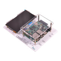
iWave i.MX 8M Nano SODIMM Hardware User's Manual (62 pages)
i.MX 8M Mini or i.MX 8M Nano SODIMM Development Platform
Brand:
iWave
| Category:
Motherboard
| Size: 5 MB
Table of Contents
Table of Contents
4
1 Introduction
8
Purpose
8
Overview
8
List of Acronyms
8
Table 1: Acronyms & Abbreviations
8
Terminlogy Description
10
References
10
Table 2: Terminology
10
2 Architecture and Design-Sodimm Carrier Board
11
I.MX 8M Mini or I.MX 8M Nano SODIMM Development Platform Block Diagram
11
Figure 1: I.MX 8M Mini or I.MX 8M Nano SODIMM SOM Development Platform Block Diagram
11
I.MX 8M Mini or I.MX 8M Nano SODIMM Development Platform Features
12
SODIMM Edge Connector
14
Figure 2: SODIMM Connector
14
Table 3: 200-Pin PCB Edge Connector Pin Assignment
15
Serial Interface Features
26
Debug UART
26
Figure 3: Debug UART
26
Table 4: Debug UART Connector Pin out
26
Data UART Header
27
Figure 4: Data UART Header
27
Table 5: Data UART Header Pin out
27
Communication Features
28
10/100/1000Mbps Ethernet -1
28
Figure 5: 10/100/1000Mbps RJ45 Magjack -1
28
10/100/1000 Mbps Ethernet-2 (Optional) (Not Available in Nano)
29
Figure 6: 10/100/1000Mbps RJ45 Magjack-2
29
USB2.0 Device
30
Figure 7: USB2.0 Device Port
30
USB2.0 Host (Not Available in Nano)
31
Figure 8: USB 2.0 Host Ports
31
Microsd Slot
32
Figure 9: Micro SD Connector
32
High Speed Interfaces
33
Mini Pcie Port
33
Figure 10: Mini Pcie Slot
33
Table 6: Mini Pcie Slot Pinout
33
Audio/Video Features
36
Audio IN/OUT Jack
36
Figure 11: Audio IN/OUT Jack
36
Table 7: Audio In/Out Jack Pin out
36
Additional Features
37
MIPI CSI Camera Connector
37
Figure 12: MIPI CSI Camera FPC Connector
37
Table 8: 40 Pin -MIPI CSI Camera FPC Connector
38
MIPI DSI Display Interface Connector
39
Figure 13: MIPI DSI Display Interface Connector
39
Table 9: 20 Pin -MIPI DSI Connector Pin out
40
Boot Mode Switch
41
Figure 14: Boot Switch
41
Table 10: I.MX 8M Mini Boot Mode Settings
41
Reset Switch
42
Figure 15: Reset Switch
42
Table 11: I.MX 8M Nano Boot Mode Settings
42
Power On/Off Switch
43
JTAG Header
43
Figure 16: Power On/Off Switch
43
Figure 17: JTAG Header
44
Table 12: JTAG Header
44
RTC Coin Cell Holder
45
Expansion Header
45
Figure 18: RTC Coin Cell Holder
45
Table 13: RTC Coin Cell Holder Pin out
45
Figure 19: Expansion Header
46
Table 14: Expansion Header Pin out
46
GPIO Header
47
Figure 20: GPIO Header
47
Table 15: GPIO Header Pin out
48
3 Architecture and Design-Sodimm Mipi Daughter Board
49
I.MX 8M Mini or I.MX 8M Nano SODIMM MIPI Daughter Board Block Diagram
49
Figure 21: SODIMM MIPI Daughter Board Block Diagram
49
SODIMM MIPI Daughter Board Features
50
Figure 22: SODIMM MIPI Daughter Board MIPI Connectors
50
Video Features
51
MIPI DSI Display
51
Figure 23: MIPI DSI Display Connector
51
Table 16: MIPI Display Connector Pinout
51
MIPI CSI Camera
53
Figure 24: MIPI Camera Connector
53
Table 17: MIPI Camera Connector Pin out
53
4 Technical Specification
55
Electrical Characteristics
55
Power Input Requirement
55
Figure 25: Power Jack
55
Table 18: Power Jack Pin out
55
Table 19: Power Input Requirement
56
Environmental Characteristics
57
Environmental Specification
57
Rohs Compliance
57
Electrostatic Discharge
57
Table 20: Environmental Specification
57
Mechanical Characteristics
58
I.MX 8M Mini or I.MX 8M Nano SODIMM Carrier Board Mechanical Dimensions
58
Figure 26: Mechanical Dimension of I.MX 8M Mini or I.MX 8M Nano SODIMM Carrier Board
58
Figure 27: Mechanical Dimension of I.MX 8M Mini or I.MX 8M Nano Carrier Board - Side View
58
5 Ordering Information
59
Table 21: I.MX 8M Mini Orderable Product Part Numbers
59
Table 22: I.MX 8M Nano Orderable Product Part Numbers
60
6 Appendix
61
Guidelines to Insert the I.MX 8M Mini or I.MX 8M Nano SODIMM SOM into Carrier Board
61
Guidelines to Remove the I.MX 8M Mini or I.MX 8M Nano SODIMM SOM from Carrier Board
61
Figure 28: I.MX 8M Mini or I.MX 8M Nano SODIMM Module Insertion Procedure
61
Figure 29: I.MX 8M Mini or I.MX 8M Nano SODIMM Module Removal Procedure
61
Advertisement
Advertisement
Related Products
iWave i.MX 8M Nano SODIMM SOM
iWave i.MX 8M Plus SMARC
iWave i.MX 8M Mini SODIMM SOM
iWave i.MX8M Quad
iWave i.MX8M QuadLite
iWave iW-RainboW-G21D
iWave iW-RainboW-G27M
iWave iW-RainboW-G34D
iWave iW-G36S-4EV1-4E002G-E008G-BIA
iWave iW-G36S-4EV1-4E002G-E008G-BIB
iWave Categories
Motherboard
Computer Hardware
Single board computers
Control Unit
Microcontrollers
More iWave Manuals
Login
Sign In
OR
Sign in with Facebook
Sign in with Google
Upload manual
Upload from disk
Upload from URL