Sign In
Upload
Manuals
Brands
ISA Manuals
Test Equipment
STS 5000
ISA STS 5000 Substation Test Set Manuals
Manuals and User Guides for ISA STS 5000 Substation Test Set. We have
1
ISA STS 5000 Substation Test Set manual available for free PDF download: Manual
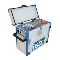
ISA STS 5000 Manual (78 pages)
For the test of CT, VT and PT
Brand:
ISA
| Category:
Test Equipment
| Size: 2 MB
Table of Contents
Specifications
0
Table of Contents
2
1 General
5
Sts Family Models
5
Table 2 - Differences Among the Sts Family Models
5
Table 3 - Current Transformer Tests
5
Table 4 - Voltage Transformers Tests
6
Table 5 - Power Transformers Tests
6
Table 6 - Circuit Breakers Tests
6
Table 7 - Resistances Tests
6
Table 8 - Optional Modules
8
Figure 1 - Sts 5000
10
Figure 2 - Test Set Front Panel
11
Table 9 - Frontal Panel Components (1/2)
11
Table 10 - Frontal Panel Components (2/2)
12
Figure 3 - Left Panel Components
13
Table 11 - Left Panel Components
13
Figure 4 - Right Panel Components
14
Table 12 - Right Panel Components
14
2 Applicable Standards
15
Table 13 - Standards Related to the Emc Directive (2/2)
15
Table 14 - Standards Related to the Lv Directive
16
3 Characteristics
17
Foreword
17
Main Generator
17
High AC Current
18
High DC Current
18
Table 15 - High Ac Current : Output Characteristics (1/2)
18
Table 16 - High Ac Current : Output Characteristics (2/2)
18
Table 17 - High DC Current : Output Characteristics (1/2)
18
Table 18 - High DC Current : Output Characteristics (2/2)
18
Low AC Current
19
Low DC Current
19
Table 19 - Low AC Current: Output Characteristics
19
Table 20 - Low DC Current: Output Characteristics
19
High AC Voltage
20
Table 21 - High Ac Voltage : Output Characteristics (1/4)
20
Table 22 - High Ac Voltage : Output Characteristics (2/4)
20
Table 23 - High Ac Voltage : Output Characteristics (3/4)
20
Low AC Voltage
21
Table 24 - High Ac Voltage : Output Characteristics (4/4)
21
Table 25 - High AC Voltage: Current Ranges and Associated Errors
21
Table 26 - High AC Voltage: Phase Shift Metering Characteristics
21
Table 27 - Low AC Current: Output Characteristics
21
High Power Output to the External Modules
22
Output Frequency
22
Other Features of Main Outputs
22
Table 28 - High Power Output: Output Characteristics
22
Table 29 - Frequency Range on All the Ac Outputs
22
Table 30 - Other Features of Main Outputs
22
Outputs Measurement
23
External Inputs Measurement
23
Table 31 - Outputs Measurement
23
Table 32 - Resolution and Accuracy
23
Timer
24
Phase Angle
24
Table 33 - Phase Angle Resolution and Accuracy
24
Other Measurements
25
Table 34 - Available Measurements
25
Table 35 - Parameters for Ct, Vt and Pt Ratio Measurement
25
Table 36 - Parameters for the Burden Test
25
Table 37 - Resistance Test: Range and Accuracy
26
Table 38 - Impedance Test: Range and Accuracy
26
Table 39 - Phase Angle Resolution and Accuracy
26
Display
27
Test Control
27
Table 40 - Main Features of the Display
27
3.10 Menu Selections
28
Figure 6 - Home Page
28
Figure 7 - "Current Transformers Icon
28
Figure 8 - "Current Transformers/Header and Nominal Values" Page (Tab Description)
29
Figure 9 - "Current Transformers/Header and Nominal Values" Page (Tab Nominals)
29
Figure 10 - "Current Transformers/Header and Nominal Values" Page (Tab Tolerances)
30
Figure 11 - "Current Transformers " Test Page
30
Figure 12 - "Cts - Ratio Polarity and Burden Current Method" Page
31
Table 41 - Current Transformers Tests (1/4)
32
Table 42 - Current Transformers Tests (2/4)
33
Table 43 - Current Transformers Tests (3/4)
34
Table 44 - Current Transformers Tests (4/4)
35
Table 45 - Voltage Transformers Tests (1/2)
36
Table 46 - Voltage Transformers Tests (2/2)
37
Table 47 - Power Transformers Tests (1/3)
38
Table 48 - Power Transformers Tests (2/3)
39
Table 49 - Power Transformers Tests (3/3)
40
Table 50 - Circuit Breakers Tests
41
Table 51 - Resistances Tests (1/2)
42
Table 52 - Resistances Tests (2/2)
43
Table 53 - Other Possible Tests
44
Standard Connection Cables (Long Cables Code Pii16175 and Extra Long Cables Code Pii57175)
45
Table 54 - Cables Provided with the Unit
45
3.12 Other Characteristics
46
Table 55 - Other Characteristics of the Sts
46
4 Options
47
Transit Cases (Code PII17175, PII 19175, PII51175)
47
Figure 13 - Transit Case
47
Table 56 - Transit Case Main Characteristics
47
Table 57 - Transport Cases Coding
47
PADS Licence (Code PII10176P, PII10176F, PII10176T)
48
Remote Safety Switch (Code PII42175)
49
Warning Strobe Light (Code PII43175)
49
Figure 14 - Remote Safety Switch
49
Figure 15 - Warning Strobe Light
49
Figure 16 - Safety Warnings (28) Connector
49
STCS Automatic Connection Windings Module (Code PII12175)
50
STCS Power Generator Booster 20 a DC (Code PII32175)
51
B Ooster 20 a DC ( Code Pii32175)
51
STDE Residual Magnetization Removal Module (Code PII27175)
52
STSA Surge Arrester (Code PII46175)
53
BUX 3000, BUX 2000 Current Booster (Codes PII50175, PII56175)
53
Figure 21 - Bux 3000 Option
53
Rrester ( Code Pii46175)
53
Table 60 - Max Test Currents and Durations (230 V) for Bux 3000
54
Table 61 - Max Test Currents and Durations (110 V) for Bux 3000
54
Table 62 - Max Test Currents and Durations (230 V) for Bux 2000
54
Current Clamp (Code PII16102)
55
Figure 22 - Current Clamp
55
Table 63 - Max Test Currents and Durations (110 V) for Bux 2000
55
Table 64 - Current Clamp Main Characteristics
55
PLCK Polarity Checker (Code PII41175)
56
STLG Current Injection Power Transformer for Ground Tests (Code PII70175)
56
Figure 23 - Plck Option
56
Figure 24 - Stlg Option
56
C Hecker ( Code Pii41175)
56
Power Factor Correction Module (Code PII85175)
57
STLG Large Station (Code PII88175)
58
Table 65 - Kit Elements (1/2)
58
Table 66 - Kit Elements (2/2)
59
STSG Safety Grounding Module (Code PII71175)
60
Figure 25 - Stsg Option
60
Cylindrical Studs
61
Surge Arrester for STSG (Code PII77175)
61
Table 67 - Studs Characteristics
61
Ground Grid Test Accessories Kit (Code PII76175)
62
Figure 26 - Ground Grid Test Accessories Kit
62
Table 68 - Elements of the Ground Grid Test Accessories Kit
62
Current Clamp Meter (Code PII79175)
63
Figure 27 - Current Clamp Meter
63
Table 69 - Current Clamp Meter Main Characteristics
63
Foldable Trolley (Code PII18175)
64
TD 5000 Module for the tan(Δ) Loss Angle Factor Measure (Code PII11175)
64
Figure 28 - Foldable Trolley
64
Figure 29 - Td 5000
64
Table 70 - Trolley Characteristics
64
Figure 30 - Power Supply on the Side
65
Figure 32 - Hv Output on the Front Panel
66
Table 71 - Hv Generator Main Characteristics
66
Table 72 - Voltage and Current Output Measurement Accuracy and Resolution
66
Table 73 - Frequency Characteristics of Td 5000
67
Table 74 - Derived Measurements from the Measurements of Vandi
67
Table 75 - Cables Supplied with Td 5000
68
Table 76 - Parasitic Capacitances
69
CAP-CAL Reference Capacitor (Code PII40175)
70
Figure 34 - Connection of the Cap-Cal to the Td 5000
70
STOIL Cell for the Insulating Oil Check (Code PII13175)
71
Figure 36 - Digital Thermo Hygrometer
71
Figure 37 - Rctd Option
72
Table 77 - Digital Thermo Hygrometer Main Characteristics
72
Protections
74
Table 80 - Revisions
75
Advertisement
Advertisement
Related Products
ISA STS 4000
ISA STS 3000 light
ISA SuperCapri Series
ISA Stratos Series
ISA BTS200 MKII
ISA DRTS.3 PLUS
ISA MC5
ISA T1000
ISA T1000 PLUS
ISA T2000
ISA Categories
Commercial Food Equipment
Test Equipment
Refrigerator
Display Case
Freezer
More ISA Manuals
Login
Sign In
OR
Sign in with Facebook
Sign in with Google
Upload manual
Upload from disk
Upload from URL