Sign In
Upload
Manuals
Brands
Intelligent Motion Systems Manuals
Computer Hardware
MDrive DSP-402
Intelligent Motion Systems MDrive DSP-402 Manuals
Manuals and User Guides for Intelligent Motion Systems MDrive DSP-402. We have
1
Intelligent Motion Systems MDrive DSP-402 manual available for free PDF download: Application Manual
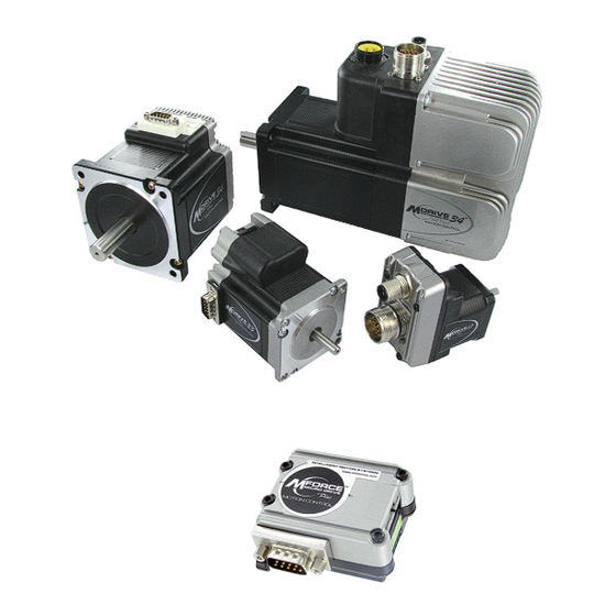
Intelligent Motion Systems MDrive DSP-402 Application Manual (64 pages)
Intelligent Motion Systems, Inc. Motion Control Application Guide
Brand:
Intelligent Motion Systems
| Category:
Computer Hardware
| Size: 3 MB
Table of Contents
Table of Contents
3
Section 1: Introduction to the Mdriveplus Canopen DSP-402 Implementation
11
Introduction
11
CAN Message Format
11
Mdriveplus Architecture
11
Figure 1.1: Message Format
11
Figure 1.2: Mdriveplus Architecture
11
Device Control
12
Modes of Operation
12
Homing Mode
12
Profile Position Mode
12
Profile Velocity Mode
12
Figure 1.3: Functional Architecture
12
Trajectory Generator
13
Objects and the Object Dictionary
13
Figure 1.4: Mdriveplus Canopen Object Dictionary
13
Table 1.1: Object Dictionary
13
Object Formatting
14
Object Description
14
Entry Description
14
Sub-Indexes
15
Section 2: Accessing the Mdriveplus Canopen
17
Introduction
17
Process Data Object (PDO)
17
PDO Attributes
17
Service Data Object (SDO)
17
SDO Attributes
17
Figure 2.1: PDO Producer - Consumer Relationship
17
Figure 2.2: SDO Client - Server Relationship
17
PDO Mapping
18
PDO Mapping Procedure (Consumer PDO)
18
Figure 2.3: PDO Mapping Showing the Default Mapping for RPDO2
18
PDO Objects
19
Consumer PDO1 (RPDO1) 1400H (Object Description)
19
Consumer PDO1 (RPDO1) 1400H (Entry Description)
19
1600H (Object Description - Mapping Parameters)
19
1600H (Entry Description - Mapping Parameters)
19
Consumer PDO2 (RPDO2) 1401H (Object Description)
20
Consumer PDO2 (RPDO2) 1401H (Entry Description)
20
1601H (Object Description - Mapping Parameters)
20
1601H (Entry Description - Mapping Parameters)
20
Consumer PDO3 (RPDO3) 1402H (Object Description)
21
Consumer PDO3 (RPDO3) 1402H (Entry Description)
21
1602H (Object Description - Mapping Parameters)
21
1602H (Entry Description - Mapping Parameters)
21
Producer PDO1 (TPDO1) 1800H (Object Description)
21
Producer PDO1 (TPDO1) 1800H (Entry Description)
22
1A00H (Object Description - Mapping Parameters)
22
1A00H (Entry Description - Mapping Parameters)
22
Producer PDO2 (TPDO2) 1801H (Object Description)
22
Producer PDO2 (TPDO2) 1801H (Entry Description)
22
1A01H (Object Description - Mapping Parameters)
23
1A01H (Entry Description - Mapping Parameters)
23
Producer PDO3 (TPDO3) 1802H (Object Description)
23
Producer PDO3 (TPDO3) 1802H (Entry Description)
23
1A02H (Object Description - Mapping Parameters)
23
1A02H (Entry Description - Mapping Parameters)
24
Section 3: Manufacturer Specific Objects
25
Introduction
25
Accessibility Codes
25
Object 2000H: I/O Discretes (Config)
25
Object Description
25
Entry Description
25
Object 2002H: I/O Discretes (Config)
26
Object Description
26
Entry Description
26
Object 2004H: Input Filter Mask (Config)
26
60FD H Digital Inputs
26
Figure 3.1: Input Filter Mask
26
Entry Description
27
Object Description
27
Object 2006H: Input Filter Time (Ms)
27
Object 2010H: Analog Input
28
Object Description
28
Entry Description
28
Object 2020H: Software Limits as Hardware Limits
28
Object 2022H: Actual Position Software Limit
28
Object 2031H: Unit Options (Encoder Enable, Capture In/Trip Out)
29
Object Description
29
Entry Description
29
Object 2032H: Clock Options
29
Object 2033H: Capture Input
29
Entry Description
30
Object 2204H: Run Current Percent
30
Object Description
30
Object 2205H: Hold Current Percent
30
Object 2211H: Position Present Point Target
31
Object Description
31
Entry Description
31
Object 2212H: Position Final Point Target
31
Object 5001H: Configuration
31
Entry Description
32
Object 5002H: ASCII Serial Number
32
Object 5003H: ASCII Part Number
32
Object 5004H: Motor Parameters
32
Section 4: Device Control
33
Device Control
33
Control and Status Words
33
State Machine
33
Figure 4.1: Device Control
33
Table 4.1: State Machine States
33
Table 4.2: State Machine Transitions
34
Figure 4.2: State Machine States/Transitions Block Diagram
35
Notes on State Transitions
35
Status Word
35
Object 6040H - Controlword
36
Object Description
36
Entry Description
36
Data Description
36
Device Control Command Bit Patterns (Bits 0-3 and 7)
36
Device Operation Mode Bit Patterns (Bits 4-6 and 8)
36
Table 4.3: Mdriveplus Canopen Device Control Commands (Bits Marked X Are Not Relevant)
36
Table 4.4: Mdriveplus Canopen Operation Modes
36
Object 6041H - Statusword
37
Object Description
37
Entry Description
37
Data Description
37
Figure 4.3: Statusword Bits
37
Table 4.5: Device State Bits for Statusword
37
Section 5: Modes of Operation
39
Object 6060H - Modes of Operation
39
Object Description
39
Entry Description
39
Data Description
39
Object 6061H - Modes of Operation Display
40
Object Description
40
Entry Description
40
Data Description
40
Object 6502H - Supported Drive Modes
40
Section 6: Profile Position Mode
43
General Information
43
Input Data Description
43
Output Data Description
43
Figure 6.1: Trajectory Generator Block Diagram
43
Functional Description
44
Figure 6.2: Set-Point Transmission from Host Computer
44
Controlword (6040H) of Profile Position Mode
45
Figure 6.3: Single Set-Point Mode (Move after a Move) 6040H Bit 5=0
45
Figure 6.4: Set of Setpoints (Move on a Move) 6040H Bit 5=1
45
Table 6.1: Profile Position Mode Bits of Controlword
45
Object 6081H - Profile Velocity
46
Object Description
46
Entry Description
46
Statusword (6041H) of Profile Position Mode
46
Object 607Ah - Target Position
46
Object 6082H - End Velocity
47
Object Description
47
Entry Description
47
Object 6083H - Profile Acceleration
47
Object 6084H - Profile Deceleration
47
Object 6086H - Motion Profile Type
48
Object Description
48
Entry Description
48
Section 7: Homing Mode
49
General Information
49
Input Data Description
49
Output Data Description
49
Internal States
49
Controlword (6040H) of Profile Position Mode
49
Figure 7.1: the Homing Function
49
Statusword (6041H) of Homing Mode
50
Homing Offset (607Ch)
50
Object Description
50
Entry Description
50
Figure 7.2: Home Offset
50
6098 H Homing Method
51
Object Description
51
Entry Description
51
Data Description
51
Functional Description of Homing Methods
51
Figure 7.3: Homing on the Negative Limit and Index Pulse
51
Figure 7.4: Homing on the Positive Limit and Index Pulse
52
Figure 7.5: Homing on the Positive Home Switch and Index Pulse
52
Figure 7.6: Homing on the Negative Home Switch and Index Pulse
53
Figure 7.7: Homing on the Home Switch and Index Pulse - Positive Initial Move
53
Figure 7.8: Homing on the Home Switch and Index Pulse - Negative Initial Move
54
Methods 15 and 16: Reserved
54
Methods 31 and 32: Reserved
54
Methods 17 to 30: Homing Without an Index Pulse
54
Homing Speeds (6099H)
55
Object Description
55
Entry Description
55
Figure 7.10: Homing on the Index Pulse
55
Section 8: Position Control Function
57
General Information
57
Object 6062H - Position Demand Value
57
Object Description
57
Entry Description
57
Object 6063H - Position Actual Value Internal
57
Object 6064H - Position Actual Value
57
Object 6065H - Following Error Window
58
Object Description
58
Entry Description
58
Object 6066H - Following Error Timeout
58
Object 6068H - Position Window Time
58
Section 9: Profile Velocity Mode
59
Controlword (6040H) of Profile Velocity Mode
59
Statusword (6041H) of Profile Velocity Mode
59
Object 606Ch - Velocity Actual Value
59
Object Description
59
Entry Description
59
Table 8.1: Profile Velocity Mode Bits of Controlword
59
Table 8.2: Profile Velocity Mode Bits of Statusword
59
Object 60Ffh - Target Velocity
60
Entry Description
60
Object 60F8H - Maximum Slippage
60
Section 10: Optional Application FE (General I/O)
61
Object 60Fdh - Digital Inputs
61
Entry Description
61
Figure 10.1: Object 60FD Structure
61
Object 60Feh - Digital Outputs
62
Entry Description
62
Figure 10.2: Object 60FE Structure
62
Obtaining Warranty Service
63
Advertisement
Advertisement
Related Products
Intelligent Motion Systems MDrive34AC & 42AC Plus MDrive34AC
Intelligent Motion Systems MDrive42AC Plus Microstepping
Intelligent Motion Systems MDrivePlus CANopen DSP-402
Intelligent Motion Systems MDriveAC
Intelligent Motion Systems MDrive34AC Plus Microstepping
Intelligent Motion Systems MDrive34CAC Plus Microstepping
Intelligent Motion Systems MDrive42AC Plus-65 Microstepping
Intelligent Motion Systems MDrive AC Plus 34
Intelligent Motion Systems MDrive AC Plus Series
Intelligent Motion Systems MDrive AC Plus 42
Intelligent Motion Systems Categories
Computer Hardware
Home Safety Product
DC Drives
Engine
Media Converter
More Intelligent Motion Systems Manuals
Login
Sign In
OR
Sign in with Facebook
Sign in with Google
Upload manual
Upload from disk
Upload from URL