Sign In
Upload
Manuals
Brands
Intel Manuals
Computer Hardware
Atom D2700
Intel Atom D2700 Manuals
Manuals and User Guides for Intel Atom D2700. We have
1
Intel Atom D2700 manual available for free PDF download: User Manual
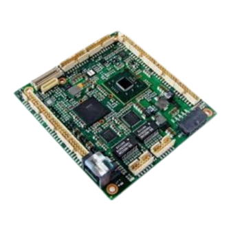
Intel Atom D2700 User Manual (114 pages)
Embedded Processor with Intel NM10 Express Chipset
Brand:
Intel
| Category:
Computer Hardware
| Size: 5 MB
Table of Contents
Table of Contents
6
1 Development Kit Contents
11
1.1 Included Hardware and Documentation
11
1.2 Development Kit Images
12
Front
12
Inside
12
Back
12
2 Intel Embedded Board D2700 Overview
13
Overview
13
Feature Summary
13
Table 1. Feature Summary
13
Board Layout
15
Figure 1. Major Board Components (Top)
15
Table 2. Board Components Shown in Figure 1
16
Block Diagram
17
Figure 2. Block Diagram of Development Kit
17
Online Support
18
Supported Operating Systems
18
BIOS Vendors
19
Processor
19
Intel ® Embedded Board D2700 Graphics Subsystem
20
System Memory
21
Table 3. Summary of the Resolution of the Graphics Interfaces
21
Table 4. Supported Memory Configurations
22
Figure 3. Memory Channel and SO-DIMM Configuration
23
Intel ® NM10 Express Chipset
24
Video Memory Allocation
24
Analog Display (VGA)
24
Digital Visual Interface (DVI-I)
24
Flat Panel Interface (LVDS)
24
Configuration Modes
25
Usb
26
SATA Support
26
Real-Time Clock Subsystem
27
Legacy I/O Controller
27
Serial Ports
28
Parallel Port
28
Keyboard and Mouse Interfaces
28
2.10 LAN Subsystem
29
Intel ® 82574L Gigabit Ethernet Controllers
29
LAN Subsystem Software and Drivers
29
RJ-45 LAN Connector with Integrated Leds
30
Figure 4. LAN Connector LED Locations
30
Table 5. LAN Connector LED States
30
2.11 Audio Subsystem
31
Table 6. Audio Jack Support
31
Audio Connectors and Headers
32
Audio Subsystem Software
32
Figure 5. Back Panel Audio Connectors
32
2.12 Hardware Management Subsystem
33
Hardware Monitoring
33
Thermal Monitoring
34
Figure 6. Thermal Sensors and Fan Header
34
2.13 Power Management
35
Acpi
35
Table 7. Effects of Pressing the Power Switch
35
Table 8. Power States and Targeted System Power
36
Table 9. Wake-Up Devices and Events
37
Hardware Support
38
Figure 7. Location of the Standby Power Indicator LED
40
2.14 Debug Interfaces
41
3 Technical Reference
42
Memory Map
42
Addressable Memory
42
Figure 8. Detailed System Memory Address Map
43
Table 10. System Memory Map
44
Connectors and Headers
45
Back Panel
46
Figure 9. Back Panel Connectors
46
Figure 10. I/O Shield Reference Diagram
47
Component-Side Connectors and Headers
48
Figure 11. Component-Side Connectors and Headers
48
Table 11. Component-Side Connectors and Headers Shown in Figure 11
49
Table 12. TPM Header
50
Table 13. Serial Port Headers
50
Table 14. LVDS Data Connector
51
Table 15. Backlight Inverter Voltage Selection Jumper
52
Table 16. FPD Brightness Connector
52
Table 17. Flat Panel Voltage Selection Jumper
52
Table 18. System Fan Header
53
Table 19. SATA Connectors
53
Table 20. Front Panel Wireless Activity LED Header
53
Table 21. Front Panel Audio Header for Intel ® HD Audio
53
Table 22. Front Panel Audio Header for AC '97 Audio
53
Table 23. Front Panel USB 2.0 Headers
54
Table 24. Front Panel USB Header with Intel ® Z-U130 USB Solid-State Drive or
54
Table 25. Internal S/PDIF Header
54
Table 26. Parallel Port Header
55
Table 27. Power Connector
57
Figure 12. Connection Diagram for Front Panel Header
58
Table 28. Front Panel Header
58
Table 29. States for a One-Color Power LED
59
Figure 13. Connection Diagram for Front Panel USB 2.0 Header
60
Figure 14. Connection Diagram for Front Panel USB 2.0 Header with Intel Z-USB Solid-State Drive or Compatible Device Support
60
BIOS Configuration Jumper Block
61
Figure 15. Location of the BIOS Configuration Jumper Block
61
Table 30. BIOS Configuration Jumper Settings
62
Mechanical Considerations
63
Form Factor
63
Figure 16. Board Dimensions
63
Electrical Considerations
64
Fan Header Current Capability
64
Add-In Board Considerations
64
Table 31. Fan Header Current Capability
64
Power Consumption
65
Minimum Load Configuration
65
Maximum Load Configuration
65
Table 32. Minimum Load Configuration Current and Power Results
65
Reliability
66
Environmental
66
Table 33. Maximum Load Configuration Current and Power Results
66
Table 34. Intel
66
4 Overview of BIOS Features
67
Introduction
67
BIOS Flash Memory Organization
68
Resource Configuration
68
PCI* Autoconfiguration
68
Table 35. BIOS Setup Program Menu Bar
68
Table 36. BIOS Setup Program Function Keys
68
System Management BIOS (SMBIOS)
69
Legacy USB Support
70
BIOS Updates
71
BIOS Recovery
71
Table 37. Acceptable Drives/Media Types for BIOS Recovery
71
Custom Splash Screen
72
Boot Options
72
Optical Drive Boot
72
Network Boot
72
Booting Without Attached Devices
73
Changing the Default Boot Device During POST
73
Adjusting Boot Speed
73
Peripheral Selection and Configuration
73
Table 38. Boot Device Menu Options
73
BIOS Boot Optimizations
74
BIOS Security Features
75
Table 39. Supervisor and User Password Functions
75
5 Board Status and Error Messages
76
BIOS Beep Codes
76
Table 40. BIOS Beep Codes
76
Front-Panel Power LED Blink Codes
77
BIOS Error Messages
77
Table 41. Front-Panel Power LED Blink Codes
77
Table 42. BIOS Error Messages
77
Port 80H POST Codes
78
Table 43. Port 80H POST Code Ranges
78
Table 44. Port 80H POST Codes
79
Table 45. Typical Port 80H POST Sequence
82
6 Assembly/Disassembly Guide
83
6.1 Introduction
83
6.2 Required Tools
83
6.3 Board Installation Steps
84
Figure 17 -- Removing the Top Lid
84
Figure 18-Install Motherboard
84
6.4 Installing USB Devices under the Front Plate
85
Figure 19 -- J2 (USB Header) and J3 (2X3) Pin Header, View from the Back of Enclosure
85
Figure 20 -- Removing the Front Plate by Pressing the Left and Right Plastic Lids
85
Figure 21 -- JP1, JP2 Pin Header and 2 X USB Slots
85
6.5 Installing SSD and Fans
86
Figure 22: Mount Bracket for HDD, SSD, or Fan
86
7 Operating System Reference
87
Installing Windows* 7
87
Downloading and Installing Windows 7 Onto the Target SSD/HDD
87
Table 46. Windows 7 Installation Options
88
Downloading and Installing Processor, Graphics, Chipset and Other Optional Drivers
89
Installing Windows* Embedded Standard 7
89
Downloading, Burning, and Installing the WES7 DVD Image
90
Install WES7
90
Figure 23: Build an Image
91
Figure 24: Accept the License Terms
91
Figure 25: View Template
92
Figure 26: Template Details
92
Figure 27: Choose a Language and Other Preferences
93
Figure 28: Where Do You Want to Install Windows
93
Downloading and Installing Processor, Graphics, Chipset and Other Optional Drivers
94
Figure 29: Installing Windows
94
Figure 30: Set up Windows - Login
94
Installing Windows Embedded Compact 7
95
Installing Windows XP
95
Overview
95
F6 Install with Floppy
96
Slipstream Install
100
Install Device Drivers
103
Install and Configure EMGD
103
Using Meego
104
Booting Meego
104
Live Image on USB Stick
104
Install with USB Stick
105
Graphics Driver
106
Flash
106
Using Yocto Project
106
Booting Yocto Project
107
Live Image on USB Stick
107
Install with USB Stick
108
Install with CD or DVD
109
Graphics Driver
109
8 Battery Disposal
110
Advertisement
Advertisement
Related Products
Intel DBPXA210
INTEL CORE 2 DUO E6000 - UPDATE 3-2008
Intel D815EEA
Intel Core 2 Duo E6400
Intel Core 2 Duo SU9400
Intel Core 2 Duo E6550
Intel Core 2 Duo E6700
Intel Core 2 Duo E6600
Intel Core 2 Duo E6320
Intel Core 2 Duo E4500
Intel Categories
Motherboard
Computer Hardware
Server
Desktop
Server Board
More Intel Manuals
Login
Sign In
OR
Sign in with Facebook
Sign in with Google
Upload manual
Upload from disk
Upload from URL