Sign In
Upload
Manuals
Brands
Inrevium Manuals
Computer Hardware
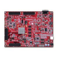
TB-7VX-1140T-PCIEXP
Inrevium TB-7VX-1140T-PCIEXP Manuals
Manuals and User Guides for Inrevium TB-7VX-1140T-PCIEXP. We have
2
Inrevium TB-7VX-1140T-PCIEXP manuals available for free PDF download: Hardware User Manual, Startup Manual
Inrevium TB-7VX-1140T-PCIEXP Hardware User Manual (61 pages)
Brand:
Inrevium
| Category:
Computer Hardware
| Size: 3 MB
Table of Contents
Table of Contents
3
Related Documents and Board Accessories
8
Overview
8
Feature
8
Block Diagram
9
Figure 4-1 Block Diagram
9
External View of the Board
10
Board Specification
10
Figure 5-1 Component Side of the Board
10
Figure 6-1 Board Dimension Diagram
11
Description of each Component
12
Power Supply Structure
12
Figure 7-1 Power Supply Structure
12
Oscillator
13
Figure 7-2 Clock Structure
13
Table 7-1 Details of Onboard Oscillator
14
Programmable Clock Generator
15
Figure 7-3 Programable Clock Connection
15
Clock Switch
16
Figure 7-4 Connection of Clock Switch
16
Table 7-2 Clock Selection
16
FMC Connector Interface
17
Figure 7-5 High-Pin Count Pin Layout
17
FMC1 HPC Connector (High-Pin Count)
18
Table 7-3 FMC1 Connector Pinout
18
FMC2 HPC Connector (High-Pin Count)
24
Table 7-4 FMC2 Connector Pinout
24
FMC3 HPC Connector (High-Pin Count)
30
Table 7-5 FMC3 Connector Pinout
30
FMC4 HPC Connector (High-Pin Count)
36
Table 7-6 FMC4 Connector Pinout
36
DDR3 SO-DIMM Interface
42
Figure 7-6 DIMM1 and DIMM2
42
Table 7-7 DDR3 SO-DIMM-1 Pinout
43
Table 7-8 DDR3 SO-DIMM-2 Pinout Table
46
PCI Express Edge Interface
49
Table 7-9 PCI Express Edge Pinout Table
49
Table 7-10 PCI Express Lane Width Configuration
50
PMOD Interface
51
Table 7-11 PMOD Pinout Table
51
Qspi-Flash
52
Figure 7-7 QSPI Layout
52
Table 7-12 QSPI Pinout Table
52
Usb3.0
53
Table 7-13 USB3.0 Pin Assign
53
Led 11
54
Figure 7-8 LED Layout
54
Table 7-14 LED Pinout Table
54
GPIO Interface
55
Figure 7-9 GPIO Pin Layout
55
Table 7-15 GPIO Pinout Table
55
Dipsw
56
Figure 7-10 DIPSW Structure
56
Table 7-16 DIPSW Pinout Table
56
Pushsw
57
Figure 7-11 PUSHSW Structure
57
Table 7-17 PUSHSW Pinout
57
Power Connector for FAN
58
Battery Control
58
Figure 7-12 Power Connector for FAN
58
Figure 7-13 Battery
58
Table 7-18 External Power Supply Connector Pinout Table
58
Table 7-19 Battery Control Signal Pinout Table
58
XADC Pinheader
59
Figure 7-14 XADC Structure
59
Table 7-20 XADC Pinout Table
59
Configuration
60
Initial Settings
60
Figure 9-1 Location of SW and CN(Juspmer)
60
Table 9-1 Initial Settings
60
Advertisement
Inrevium TB-7VX-1140T-PCIEXP Startup Manual (21 pages)
Brand:
Inrevium
| Category:
Computer Hardware
| Size: 1 MB
Table of Contents
Table of Contents
3
1 Overview
5
2 Design Development
5
Board
5
Reference Document
5
3 Distributed Data
6
Distributed Data Structure
6
Figure 3-1 Distributed Data Structure
6
4 Board Setup
7
TB-7K-325T-IMG Jumper Settings
7
TB-FMCL-USB30 Jumper Settings
7
Figure 4-2 TB-7K-325T-IMG Jumper Settings
7
Figure 4-3 TB-FMCL-USB30 Jumper Settings
7
TB-7V-2000T-LSI Jumper Settings
8
TB-7VX-690/980/1140T-PCIEXP Jumper Settings
8
Figure 4-2 TB-7V-2000T-LSI Jumper Settings
8
Figure 4-2 TB-7VX-690/980/1140T-PCIEXP Jumper Settings
8
Board and Cable Connections
9
Figure 4-5 TB-7K-325T-IMG + TB-FMCL-USB30 Cable Connections
9
Figure 4-5 TB-7V-2000T-LSI Cable Connections
10
Figure 4-5 TB-7VX-690/980/1140T-PCIEXP Cable Connections
10
5 FPGA Configuration
11
6 Installing Driver Software
12
Open Device Manager
12
Searching for Driver Software
12
Figure 6-1 Updating Driver Software
12
Figure 6-2 Specifying a Search Method
12
Specifying a Driver Store Folder
13
Executing Driver Installation
13
Figure 6-3 Specifying a Driver Store Folder
13
Figure 6-4 Install Driver Without Signature
13
Completion of Driver Software Installation
14
7 Downloading USB3.0 Firmware
14
Running Cycontrol.exe
14
Figure 6-5 Completion of Driver Software Installation
14
Figure 7-1 Cycontrol
14
Programming the Firmware
15
Completion of Programming
15
Figure 7-3 Completion of Programming
15
8 Running Sample Application
16
Run Fmcfx3Refdesign.exe
16
Single Access Test (Internal)
16
Figure 8-1Sample Application Structure
16
Figure 8-2Single Access Test (Internal)
16
Single Access Test (AXI)
17
Burst Access Test
17
Figure 8-3 Single Access Test (AXI)
17
Figure 8-4 Burst Access Test
17
Speed Test
18
Figure 8-5 Speed Test
18
9 Faq
19
Will the Board Run on XXX's PC
19
Does the TB-FMCL-USB30 Board Run in Standalone
19
Is an USB3.0 Cable Attached
19
Not Recognized as USB When Connected to PC. What Are the Causes of this
19
Can the Board Function as a USB3.0 Host Controller
20
Is the Associated Software Source Code Provided
20
Can Other Vendor's Carrier Boards be Connected
20
Tell Us the Operating System (OS) Support for Sample Software
20
Are Samples Corresponding to USB2.0 OTG Available
20
Advertisement
Related Products
Inrevium TB-6V-LX760-LSI
Inrevium TB-7V-2000T-LSI
Inrevium TB-FMCL-USB30
Inrevium TB-7K-325T-IMG
Inrevium TB-7VX-690T-PCIEXP
Inrevium TB-7VX-980T-PCIEXP
Inrevium TB-7Z-IAE
Inrevium TB-FMCH-VFMC-HDMI
Inrevium TB-FMCH-VBY1-AD
Inrevium TB-FMCH-HDMI2
Inrevium Categories
Computer Hardware
Motherboard
Extender
Test Equipment
Control Unit
More Inrevium Manuals
Login
Sign In
OR
Sign in with Facebook
Sign in with Google
Upload manual
Upload from disk
Upload from URL