Sign In
Upload
Manuals
Brands
Industrial Data Systems Manuals
Accessories
IDS 440
Industrial Data Systems IDS 440 Manuals
Manuals and User Guides for Industrial Data Systems IDS 440. We have
1
Industrial Data Systems IDS 440 manual available for free PDF download: Installation/Calibration/Operation
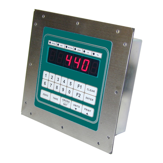
Industrial Data Systems IDS 440 Installation/Calibration/Operation (75 pages)
Weigh Scale Indicator
Brand:
Industrial Data Systems
| Category:
Accessories
| Size: 0.43 MB
Table of Contents
Table of Contents
2
Introduction
6
What's in each Section
7
Warranty Information
8
General Description
9
IDS440 Display and Keyboard Diagram
9
The IDS440 Display
10
The IDS440 Keyboard
10
Numeric Keypad
10
Function Keys
10
Control Keys
10
Installation and Setup
11
Unpacking the IDS440
11
Item Check List
11
Installation Guide
12
Connect IDS440 to Load Cell
12
Connect IDS440 to the Printer (Optional)
12
Apply AC Power to the IDS440
12
Setup Guide
14
Initialize to Factory Defaults
14
Setup & "Quick" Calibration Guide
14
Calibrate the Weight Indicator
14
Using the IDS440
15
Keyboard Layout
15
Operation of Function Keys
15
Zero
15
Tare
16
Gross/Net
16
Print
16
F1 and F2
16
Memory Register Entry
16
Execute a Scale Basic Function
16
Display Time/Date
16
Built in Application Programs
18
Fill to Setpoint
19
Installation
19
Setup Parameters
19
Operators Functions
19
Enter Setpoint
19
Start Fill Operation
19
Stop Fill Operations
19
Print Results
19
Error Codes
19
Checkweigh: Under/Between/Over
20
Installation
20
Operators Functions
20
Enter Setpoint Weights
20
Recalculate
20
Weigh-In / Weigh-Out
21
Weigh-In
21
Weigh-Out
21
Print ID's, Display ID's, Clear Totals, Erase ID's
21
Set Beginning Sequence Number
22
Options
22
Notes
22
Axle Weigh - Short Scale
23
Installation
23
Setup Parameters
23
Operators Functions
23
Axle Weigh - Long Scale, Unattended
24
Installation
24
Setup Parameters
24
Operators Functions
24
ID, Tare, and Total
25
Enter ID Tare Data
25
Recall ID and Tare
25
Print and Total ID
25
Print ID's, Display ID's, Clear Totals, Erase ID's
25
Set Beginning Sequence Number
26
Notes
26
Peak Hold Function
26
Enable Peak Hold
26
Clear Peak Hold Register
26
Display Peak Weight
26
Print Peak Weight
26
Set Operation Parameters
28
Access Operation Parameters and Parameter Functions
28
Operation Parameters Reference Tables
28
Scale Parameters
29
I/O Port Parameters
29
Display Intensity, Battery, Watchdog Timer
30
Fixed Setpoints
30
Keyboard Events
30
Parameter Functions
31
Scale Parameters
32
Parameter 1. Load Cell MV/V
32
(3 MV/V)
32
Parameter 2. Digital Filter (9)
32
Parameter 3. Display Update Rate (1)
32
Parameter 4. Motion Detection Delay (6)
33
Parameter 5. Motion Detection Band (6)
33
Parameter 6. Display Blanking During Motion (no Blanking)
33
Parameter 7. Zero Tracking Delay (0)
33
Parameter 8. Zero Tracking Band (12)
33
Parameter 9. Push Button Zero Percent (100)
34
Parameter 10. Primary Units Type (1 [Lb])
34
Parameter 11. Decimal Point Position (0 [No Decimal Point])
34
Parameter 12. Count-By (1)
34
Parameter 13. Alternate Units Type (2 [Kg])
35
Parameter 14. Alternate Decimal Point (1)
35
Parameter 15. Alternate Count-By (5)
35
Parameter 16. Alt Units Conversion Factor (45,360)
35
Parameter 17. Full Scale Graduations (10,000)
36
Parameter 18. Overload Graduations (10,200)
36
Parameter 19. Deadload Offset
36
Parameter 20. Disable Power-On Zero (1 [Disabled])
36
Parameter 21. Deadload Factor
36
Parameter 22. Weight Conversion Factor
36
Serial I/O Ports
37
Parameter 23 Serial Port 1 Mode (4 [8 Data Bits, no Parity])
37
Parameter 24 Serial Port 1 Baud Rate (1 [9600 Baud])
37
Parameter 25 Serial Port 2 Mode (4 [8 Data Bits, no Parity])
38
Parameter 26 Serial Port 2 Baud Rate (1 [9600 Baud])
38
Parameter 27 TX2 Control / Station ID (255 [Single Station])
38
Parameter 28 TX2 Format (2 Condec Format)
39
Printer Parameters
40
Parameter 29 Printer Port Select (2 [Serial Port 1])
40
Parameter 30 Auto Print LF after CR (1 [Yes])
40
Parameter 31 End of Print Character (12 [Form Feed])
40
Parameters 32, 33 34, 84, 85, 86, 87, 88, 89 and 90 Print Labels
40
Parameters 35, 36, 37, and 38: Print Codes
41
Parameter 39 Enable TTL Remote Control (1 [Enabled])
41
Display Intensity, Battery, Watch Dog Timer
41
Parameter 40 Display Intensity (10)
41
Parameter 41 Battery Backup (0 [No])
41
Parameter 42 Enable Watch Dog Timer (0 [No])
41
Parameters 43-50 Fixed Registers
41
Parameters 51-58 Keyboard Event Functions
42
Parameter Functions
43
Access Parameter Functions
44
Function 59 Display Calibration Audit Number
44
Function 60 Calibrate Scale - Deadload First
45
Function 61 Calibrate Scale - Span First
45
Function 62 Calibrate Deadload Only
45
Function 63 Adjust Gain Calibration
46
Adjust Gain - 5 Point Linearization
46
Function 64 Configure Passwords
47
Function 65 Configure Print Formats
48
Modify or Design a Print Format
48
Function 66 Set Time and Date
52
Function 67 Display Operation Parameters
52
Function 68 Print Operation Parameters
52
Function 69 Diagnostic Tests
53
Function 70 Initialize Operation Parameters to Factory Defaults
53
Function 71 Configure Event Monitor
54
Function 72 Scale Basic Function Editor
54
Function 73 Initialize Function Memory
54
Function 74 Configure Timers
55
Parameter 75 Enable Peak Detect
55
Parameter 76 Debug Mode for Event Monitors and Scale Basic
55
Function 78 Initialize ID Memory
55
Parameter 79 Enable Multi-Point Linearization
55
Function 80 Calibrate - Multi-Point Linearization
56
Diagnostic Tests
57
Table of Diagnostic Tests
57
Diagnostic Test 1: Serial Com Port 1 - Display Input Data
58
Diagnostic Test 2: Serial Com Port 1 - Display Errors
58
Diagnostic Test 3: Serial Com Port 1 - Transmit Data
58
Diagnostic Test 4: Serial Com Port 2 - Display Input Data
58
Diagnostic Test 5: Serial Com Port 2 - Display Errors
59
Diagnostic Test 6: Serial Com Port 2 - Transmit Data
59
Diagnostic Test 7: Test Parallel Output
59
Diagnostic Test 8: Test A/D
60
Diagnostic Test 9: Perform Internal Memory Test
60
Diagnostic Test 10: Lamp Test
60
Diagnostic Test 11: Print the EAROM Configuration Table
60
Diagnostic Tests 12 & 13: Loop Back Tests
60
Troubleshooting
61
Problems and Probable Causes
61
Error Messages
62
Hardware and Wiring
63
Load Cell Connector - TB3
63
Serial Port 1 Connector - TB 1
64
Serial Port 2 Connector - TB 2
64
TTL I/O Port Connector - TB 4
65
P.C. Board Diagram - Connectors, Jumpers, and Switches
66
Sample Cable Drawings
67
Load Cell
67
Ids150A/152/160/320
67
DT210/IDS550/IDS710/PC (Continuous Output Port)
68
Hewlett Packard Smart Wand HBCR-8Xxx Series
69
Parallel (Centronix) Printer
69
Remote Switch Inputs
70
Analog Output Option
71
IDS440 Specifications
73
Ascii Chart
75
Advertisement
Advertisement
Related Products
Industrial Data Systems IDS 410
Industrial Data Systems IDS 422
Industrial Data Systems IDS 430
Industrial Data Systems IDS 433
Industrial Data Systems Categories
Accessories
Printer
Measuring Instruments
More Industrial Data Systems Manuals
Login
Sign In
OR
Sign in with Facebook
Sign in with Google
Upload manual
Upload from disk
Upload from URL