
Related Manuals for Industrial Data Systems IDS 440

Summary of Contents for Industrial Data Systems IDS 440
- Page 1 IDS 440 Weigh Scale Indicator Installation/Calibration/Operation Version 4.2 10/3/2001 Program S440012x Industrial Data Systems, Inc. 590 W. Freedom Ave. Orange, CA 92865-2530 714-921-9212 Fax 714-998-8656 www.industrialdata.com...
-
Page 2: Table Of Contents
Table of Contents Introduction ......................1 What’s In Each Section ......................2 WARRANTY INFORMATION ....................3 General Description.................... 4 IDS440 Display and Keyboard Diagram ..................4 The IDS440 Display ........................5 The IDS440 Keyboard........................5 Numeric Keypad ........................5 Function Keys ........................5 Control Keys ........................5 Installation and Setup..................6 Unpacking the IDS440 .......................6 Item check list ........................6 Installation Guide ........................7... - Page 3 Installation ..........................15 Operators Functions.........................15 Enter setpoint weights .......................15 Recalculate ........................15 # 3 Weigh-in / Weigh-out ................16 Weigh-In ..........................16 Weigh-Out..........................16 Print ID’s, Display ID’s, Clear Totals, Erase ID’s...............16 Set Beginning Sequence Number ..................17 Options ..........................17 Notes ..........................17 # 4 Axle Weigh – Short Scale .............18 Installation ..........................18 Setup Parameters ........................18...
- Page 4 Parameter 10. Primary Units Type (1 [lb])..............29 Parameter 11. Decimal Point Position (0 [no decimal point]).........29 Parameter 12. Count-by (1)....................29 Parameter 13. Alternate Units Type (2 [kg])..............30 Parameter 14. Alternate Decimal Point (1)..............30 Parameter 15. Alternate Count-by (5) ................30 Parameter 16. Alt Units Conversion Factor (45,360) .............30 Parameter 17.
- Page 5 Parameter 75 Enable Peak Detect ..................50 Parameter 76 Debug mode for Event monitors and Scale Basic ..........50 Function 78 Initialize ID memory....................50 Parameter 79 Enable Multi-point Linearization ................50 Function 80 Calibrate - Multi-point Linearization ..............51 Diagnostic Tests ....................52 Table of Diagnostic Tests......................52 Diagnostic Test 1: Serial Com Port 1 - Display Input Data .............53 Diagnostic Test 2: Serial Com Port 1 –...
-
Page 6: Introduction
IDS440 Users Manual version 4.2 Introduction Introduction Congratulations on your purchase and welcome to the IDS440 User's Manual. This manual describes the installation, calibration and setup, and operation of the IDS440 weigh scale indicator. The IDS440 is a microprocessor based weight indicator with rugged design and state-of-the-art technology. -
Page 7: What's In Each Section
IDS440 are to be utilized. It is recommended that each installer and user review all sections of the manual and determine what information is useful to his personal needs. Installation and Setup allow a user to quickly get the IDS 440 in a working manner for simple use and testing. -
Page 8: Warranty Information
Buyer's specifications except as specifically stated in writing by Industrial Data Systems, Inc. and contained in the contract. In no case is product to be returned without first obtaining permission and a Customer Return Authorization Number (RMA) from Industrial Data Systems, Inc. -
Page 9: General Description
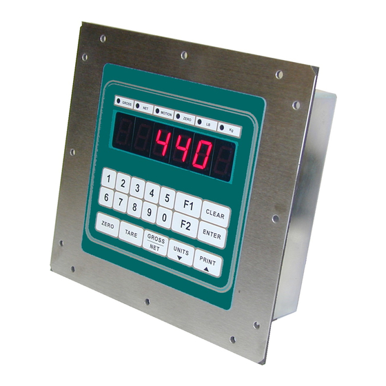
IDS440 Users Manual version 4.2 General Description General Description This section gives you a general description on the operation of the IDS440's keyboard and display. The keyboard is used to initiate weighing functions, for data entry, maintenance, setup, and testing. The numeric display is used for weight and error display and for data entry. -
Page 10: The Ids440 Display
IDS440 Users Manual version 4.2 General Description The IDS440 Display The IDS440 DISPLAY consists of a 6 character NUMERIC display and 6 statuses LED’s The NUMERIC display is normally used to display the weight on the scale. The LED’s display the scale status. When lighted they indicate the following conditions: GROSS- The number displayed is the gross weight on the scale. -
Page 11: Installation And Setup
IDS440 Users Manual version 4.2 Installation and Setup Installation and Setup This section provides information about unpacking, installing, and setup of the IDS440. It also directs the installer to the appropriate sections of the manual for hardware and setup installation. Unpacking the IDS440 Installation begins with unpacking the IDS440. -
Page 12: Installation Guide
IDS440 Users Manual version 4.2 Installation and Setup Installation Guide Connect IDS440 to load cell Connect the load cell to the Load Cell Terminal Block located inside IDS440’s enclosure. See the HARDWARE INSTALLATION AND WIRING section for pin assignments and a sample cable drawing. - Page 13 IDS440 Users Manual version 4.2 Installation and Setup 6. Stability Check - the IDS440 displays "C xxxx” where "xxxx" is the raw data difference in scale readings. The IDS440 waits until the data difference is within a stable range. To exit the above power on test functions, press the CLEAR key during any test. This is possible only if the IDS440 has not been locked.
-
Page 14: Setup Guide
IDS440 Users Manual version 4.2 Installation and Setup Setup Guide Setup the IDS440 in the following order: Initialize to Factory Defaults The IDS440 is initialized at the factory. It must be re-initialized if the program memory (EPROM) or the parameter memory (EAROM) is replaced. The Initialize function clears the memory and sets the configuration parameters to their default values. -
Page 15: Using The Ids440
IDS440 Users Manual version 4.2 Built In Application Programs Using the IDS440 The IDS440 has 7 function keys located at the bottom of the keyboard, a numeric keypad, and 2 control keys (ENTER, and CLEAR). This section of the IDS440 manual describes what the keys are used for and how to use them. -
Page 16: Tare
IDS440 Users Manual version 4.2 Built In Application Programs Tare TARE: AUTO Press the TARE key. The IDS440 reads the weight on the scale and stores it in the tare register. The IDS440 switches to NET mode and displays the net weight. KEYBOARD TARE: Use the numeric keys to enter a tare weight. - Page 17 IDS440 Users Manual version 4.2 Built In Application Programs...
-
Page 18: Built In Application Programs
IDS440 Users Manual version 4.2 Built In Application Programs Built In Application Programs The following built in programs are available: 1. Fill to Setpoint. 2. Checkweigh: Under/Between/Over. 3. Weigh-in / Weigh-out. 4. Axle Weigh – Short Scale. 5. Axle Weigh – Long Scale. 6. -
Page 19: Fill To Setpoint
IDS440 Users Manual version 4.2 Built In Application Programs #1 Fill to Setpoint Press F1 key to enter a setpoint. Place an empty container on the scale. Press F2 key to begin filling. TTL output 1 turns on until the weight on the scale is equal or greater than the setpoint. -
Page 20: Checkweigh: Under/Between/Over
IDS440 Users Manual version 4.2 Built In Application Programs # 2 Checkweigh: Under/Between/Over The indicator monitors the scale for activity. When the scale goes above the ‘empty’ weight, the indicator waits for stable weight, and then outputs an indication of Under, Between (OK), or over. -
Page 21: Weigh-In / Weigh-Out
IDS440 Users Manual version 4.2 Built In Application Programs # 3 Weigh-in / Weigh-out This program uses the ID memory for weigh-in / weigh-out transactions. An ID record is created using the Weigh-in function. The Weigh-out function recalls the ID, calculates Gross/Tare/Net of the transaction, prints the transaction, and adds the net weight to the ID’s totals register. -
Page 22: Set Beginning Sequence Number
IDS440 Users Manual version 4.2 Built In Application Programs REBUILD ID MEMORY: Press the ENTER key when the display prompts, “rebuiLd”. The display then prompts “id”. Enter the numeric 0 then press ENTER to rebuild ID memory. COUNT UNUSED ID’S: Press the ENTER key when the display prompts “Count”. The display prompts “FrExxx”... -
Page 23: Axle Weigh - Short Scale
IDS440 Users Manual version 4.2 Built In Application Programs # 4 Axle Weigh – Short Scale Automatically weigh multiple axles (or containers), print each axle weight, and print axle total. Installation Connect the Red light / Green light relays. Green light = TTL out 1 TB4 pin 1 Red light = TTL out 2... -
Page 24: Axle Weigh - Long Scale, Unattended
IDS440 Users Manual version 4.2 Built In Application Programs # 5 Axle Weigh – Long Scale, Unattended Automatically weigh multiple axles (or containers), print each axle weight, and print axle total. Installation Connect the Red light / Green light relays. Green light = TTL out 1 TB4 pin 1 Red light =... -
Page 25: Id, Tare, And Total
IDS440 Users Manual version 4.2 Built In Application Programs # 6 ID, Tare, and Total This program uses the ID memory to store tare weights and totals. Enter ID Tare Data Press the F1 key. The display prompts "id". Enter up to 8 digits for ID and then press the ENTER key. -
Page 26: Set Beginning Sequence Number
IDS440 Users Manual version 4.2 Built In Application Programs Set Beginning Sequence Number Use the numeric keypad to enter number 1. The display prompts "reg 1" for 1 second and then displays the current value. Press the CLEAR key if no change is to be made, or enter a new value and then press the ENTER key. - Page 27 IDS440 Users Manual version 4.2 Built In Application Programs...
-
Page 28: Set Operation Parameters
IDS440 Users Manual version 4.2 Set Operation Parameters Set Operation Parameters This section describes the operation parameters of the IDS440 and how their settings affect the operation of the weight indicator. Access Operation Parameters and Parameter Functions The parameters are accessed by holding the CLEAR key down and then pressing the ENTER key. -
Page 29: Scale Parameters
IDS440 Users Manual version 4.2 Set Operation Parameters Scale Parameters Parameter Name Default Max Value Pas Field Setting Loadcell mv/v Digital filter Display Update Rate Motion delay time Motion band Motion blanks display 0 (no) Zero tracking delay Zero tracking band Push button zero percent Primary units type 1 (lb) -
Page 30: Display Intensity, Battery, Watchdog Timer
IDS440 Users Manual version 4.2 Set Operation Parameters Print label 87 30 char Print label 88 30 char Print label 89 30 char Print label 90 30 char Print code 1 3 codes Print code 2 3 codes Print code 3 3 codes Print code 4 3 codes... -
Page 31: Parameter Functions
IDS440 Users Manual version 4.2 Set Operation Parameters Parameter Functions Fn. No Function Name Password Level Display Calibration Audit Number Calibrate Scale - Deadload first Calibrate Scale - span first Calibrate Deadload Only Adjust Gain Calibration Configure Passwords Configure Print Formats Set Time and Date Display Operation Parameters Print Operation Parameters... -
Page 32: Scale Parameters
IDS440 Users Manual version 4.2 Set Operation Parameters Scale Parameters The scale parameters configure IDS440 for the weigh platform or load cell that it is connected to. The preceding table titled “SCALE PARAMETERS” lists the scale parameters and their factory settings. Use the “Field Setting” column to record any changes made to the factory default values. -
Page 33: Parameter 4. Motion Detection Delay (6)
IDS440 Users Manual version 4.2 Set Operation Parameters Parameter 4. Motion Detection Delay (6) Motion detection delay is used by the motion detection function to determine if the scale is in motion (not stable). Enter the amount of time (in tenths of a second) that the scale must be stable for motion status to be false (scale status = stable). -
Page 34: Parameter 9. Push Button Zero Percent (100)
IDS440 Users Manual version 4.2 Set Operation Parameters Parameter 9. Push Button Zero Percent (100) Enter the percent of full-scale capacity that can be acquired as the zero point with the ZERO key. 1 = 1%, 2 = 2%, ... 100 = 100%. Parameter 10. -
Page 35: Parameter 13. Alternate Units Type (2 [Kg])
IDS440 Users Manual version 4.2 Set Operation Parameters Parameter 13. Alternate Units Type (2 [kg]) Alternate units are the alternate display and print unit of measure that can be used in addition to the primary units. The UNITS switch on the IDS440’s keyboard toggles the weight display between primary units and secondary units. -
Page 36: Parameter 17. Full Scale Graduations (10,000)
IDS440 Users Manual version 4.2 Set Operation Parameters Parameter 17. Full Scale Graduations (10,000) Enter the number of graduations at full scale. The full-scale graduations are calculated using the count-by, decimal position, and full-scale weight. Full Scale Graduations = Full Scale Weight / count-by. For example, if Full Scale Weight = 600.0 and count-by = 0.2 then Full Scale Graduations = 600.0 / 0.2 = 3000. -
Page 37: Serial I/O Ports
IDS440 Users Manual version 4.2 Set Operation Parameters Serial I/O Ports The IDS440 is equipped with two bi-directional serial communication ports that can communicate to an optional printer, a computer, bar code reader, a score board or other serial communication devices. The baud rate and format can be set independently for each port. -
Page 38: Parameter 25 Serial Port 2 Mode (4 [8 Data Bits, No Parity])
IDS440 Users Manual version 4.2 Set Operation Parameters Parameter 25 Serial Port 2 Mode (4 [8 data bits, no parity]) Enter the mode number from the table below to select the mode parameter in the mode description column. Mode Number Mode Description 7 data bits, no parity 7 data bits, even parity... -
Page 39: Parameter 28 Tx2 Format (2 Condec Format)
IDS440 Users Manual version 4.2 Set Operation Parameters Parameter 28 TX2 Format (2 Condec format) Serial Port 2 can be used for continuous transmission of scale data. The TX2 Format parameter determines what is sent. There are 5 selections: 1 - AND: <status>, <mode>, <polarity><weight><units><terminate> Status: OL (overload), ST (stable), US (unstable, in motion) Mode:... -
Page 40: Printer Parameters
IDS440 Users Manual version 4.2 Set Operation Parameters Printer Parameters The IDS440 provides a universal printer interface for various printers. The printer interface allows you to select and customize the data output for serial or parallel printers. The serial interface option uses Serial Port 1 (TB1) for connection to the printer. The parallel interface uses the TTL I/O Port (TB4) for connection to the printer. -
Page 41: Parameters 35, 36, 37, And 38: Print Codes
IDS440 Users Manual version 4.2 Set Operation Parameters Parameters 35, 36, 37, and 38: Print Codes The IDS440 provides 4 programmable print codes. The print codes are used to send special setup parameters to the printer, such as select print size or select print font. Each print code is up to 4 characters long. -
Page 42: Parameters 51-58 Keyboard Event Functions
IDS440 Users Manual version 4.2 Set Operation Parameters Parameters 51-58 Keyboard Event Functions The keyboard event functions determine what actions take place when a key is pressed. The Power on start function activates a function when power is applied to the indicator. Number Parameter Name Default Value Password... -
Page 43: Parameter Functions
IDS440 Users Manual version 4.2 Parameter Functions Parameter Functions The parameter functions are used to set parameters that are too complex for a single numeric entry. The following table lists the parameter functions: Parameter Functions Fn. No Function Name Password Level Display Calibration Audit Number Calibrate Scale - deadload first Calibrate Scale - span first... -
Page 44: Access Parameter Functions
IDS440 Users Manual version 4.2 Parameter Functions Access Parameter Functions Hold the CLEAR key down and press the ENTER key. The numeric display prompts “CFG xx” where xx is the currently selected parameter. Enter a parameter function number and then press the ENTER key. NOTE: use the UNITS key (↓) and the PRINT key (↑) to scroll the CFG parameter number. -
Page 45: Function 60 Calibrate Scale - Deadload First
IDS440 Users Manual version 4.2 Parameter Functions Function 60 Calibrate Scale - Deadload First Use function 60 to calibrate the scale by reading the deadload first and then reading the span. Set the Scale Operation Parameters before using function 60. Best results are obtained when the IDS440 and load cells have reached thermal equilibrium (power applied for approximately 30 to 120 minutes depending on load cell size). -
Page 46: Function 63 Adjust Gain Calibration
IDS440 Users Manual version 4.2 Parameter Functions Function 63 Adjust Gain Calibration Use function 63 to make small adjustments to the span calibration factor. Zero the scale and then place a known weight on the scale. 1. Hold the CLEAR key down and press the ENTER key to enter the configure mode. 2. -
Page 47: Function 64 Configure Passwords
IDS440 Users Manual version 4.2 Parameter Functions Function 64 Configure Passwords Use function 64 to enter password data. The IDS440 provides two security passwords that can be activated and entered to protect configuration data. Password 1 is used to protect I/O port configuration, setpoint, and event monitor data. Password 2 is used to protect calibration and scale configuration data. -
Page 48: Function 65 Configure Print Formats
IDS440 Users Manual version 4.2 Parameter Functions Function 65 Configure Print Formats Use function 65 to modify print formats to meet your print requirements. The print formats are grouped into PAGES that are used for generating print data onto a form. Each page is organized into rows and columns as follows: Line No. - Page 49 IDS440 Users Manual version 4.2 Parameter Functions Page List FORMAT DESCRIPTION PAGE 1 Prints when the IDS440 is in the GROSS weight mode. PAGE 2 Prints when the IDS440 is in the NET weight mode. PAGE 3 Used by Scale Basic functions when needed. PAGE 4 Used by Scale Basic functions when needed.
- Page 50 IDS440 Users Manual version 4.2 Parameter Functions Print Format Design Example EXAMPLE PRINT: 1111111111222222222233333333334 COLUMN 1234567890123456789012345678901234567890 LINE GROSS 54785 LB TARE 12451 LB 42243 LB TIME 03:45 PM DATE 05 AUG 1999 EXAMPLE FORMAT DESIGN WORKSHEET: Page:1 Item Description Line No. Column Item No.
- Page 51 IDS440 Users Manual version 4.2 Parameter Functions Format Design Worksheets Page Item Description Line No. Column Item No. Page Item Description Line No. Column Item No.
-
Page 52: Function 66 Set Time And Date
IDS440 Users Manual version 4.2 Parameter Functions Function 66 Set Time and Date Use function 66 to set the time and date. Entering 19 can display the time and date when the meter is in the idle mode. Date will be printed in a Y2K compliant four-digit year. 1. -
Page 53: Function 69 Diagnostic Tests
IDS440 Users Manual version 4.2 Parameter Functions Function 69 Diagnostic Tests 1. Hold the CLEAR key down and press the ENTER key to enter the configure mode. 2. Enter CFG 69. The IDS440 prompts “diA xx” where xx is the currently selected test number. -
Page 54: Function 71 Configure Event Monitor
IDS440 Users Manual version 4.2 Parameter Functions Function 71 Configure Event Monitor Use function 71 to enter setpoint data into the Event Monitor. See the “Scale Basic / Event Monitor” manual” for more information on the event monitor parameters. 1. Hold the CLEAR key down and press the ENTER key to enter the configure mode. 2. -
Page 55: Function 74 Configure Timers
2 volts. Parameter 79 Enable Multi-point Linearization Enter a to 1 to enable multi-point Linearization, enter a to 0 to disable multi-point Linearization. The IDS 440 uses the calibration factors set in function 80 below when multi-point Linearization is enabled. -
Page 56: Function 80 Calibrate - Multi-Point Linearization
Press the ENTER key to obtain the deadload weight. Press the Units key (↓) to continue without reading a new deadload weight. 3. The IDS 440 ‘s display alternates between "CAL 1" and the weight on the scale. Place the first calibration weight on the scale. Enter the calibration weight using the numeric keypad. -
Page 57: Diagnostic Tests
IDS440 Users Manual version 4.2 Diagnostic Tests Diagnostic Tests The DIAGNOSTIC TESTS are accessed using configuration function 69. Hold the CLEAR key down and press the ENTER key. The display prompts “CFG xx” where xx is the currently selected parameter. Enter 69 and press the ENTER key to access the DIAGNOSTIC TESTS. -
Page 58: Diagnostic Test 1: Serial Com Port 1 - Display Input Data
IDS440 Users Manual version 4.2 Diagnostic Tests Diagnostic Test 1: Serial Com Port 1 - Display Input Data This test displays serial data as it is received by serial communications port 1. The numeric display has limited alpha display capability, however numeric and some alpha characters are legible. -
Page 59: Diagnostic Test 5: Serial Com Port 2 - Display Errors
IDS440 Users Manual version 4.2 Diagnostic Tests Diagnostic Test 5: Serial Com Port 2 – Display Errors This test displays the number of framing and parity errors that are detected in the input data stream. The error count is set to zero when entering this test. New errors are displayed as “PxxFxx”... -
Page 60: Diagnostic Test 8: Test A/D
IDS440 Users Manual version 4.2 Diagnostic Tests Diagnostic Test 8: Test A/D This test displays the (filtered) raw data being read from the A/D converter. Use this test to determine optimum deadload and gain settings. If the number displayed at deadload is less than 1000 or greater than 250,000 then use the deadload offset (parameter 19) to add or subtract deadload from the signal input. -
Page 61: Troubleshooting
IDS440 Users Manual version 4.2 Troubleshooting Troubleshooting The following table describes the probable causes to some problems you may encounter. Most problems can be resolved by using the information provided in the table. Problems And Probable Causes Problem Probable Causes Printer does not print * Cable connection problem or invalid pin connections. -
Page 62: Error Messages
Usual cause is A/C power glitch or static electric discharge. Err 4 Battery Error. Battery voltage level was below 2 V when the IDS 440 was powered off. Err 5 Earom memory error. A checksum error has occurred when reading the configuration earom memory. -
Page 63: Hardware And Wiring
IDS440 Users Manual version 4.2 Hardware and Wiring This section describes installation and wiring information for the interface ports. There are two bi-directional serial ports, one parallel port with TTL inputs and outputs, and one load cell input port. The serial ports are used to interface to a printer and to a host device or PC for continuous output. -
Page 64: Serial Port 1 Connector - Tb 1
IDS440 Users Manual version 4.2 Serial Port 1 Connector - TB 1 For RS232 input, set switch S1 to RS232 position, and for current loop input, set the switch to CL position. NOTE: Jumper pin 7 CTS to 8 RTS if unit locks up on “Print”. Serial Port 1 - TB1 Pin # Signal Name RS232 TXD (transmit data) -
Page 65: Ttl I/O Port Connector - Tb 4
IDS440 Users Manual version 4.2 TTL I/O Port Connector - TB 4 TTL outputs 1 thru 8 will drive 24ma at TTL low level, and 8ma at TTL hi level. Output 9 is an open collector output with 4.7k-ohm resistor to +5V. TTL I/O - TB 4 Pin # Signal Name TTL Output 1 (Printer Data 1) -
Page 66: P.c. Board Diagram - Connectors, Jumpers, And Switches
IDS440 Users Manual version 4.2 P.C. Board Diagram - Connectors, Jumpers, and Switches RS232 test connector SW 1 Serial Port 1 Serial Port 2 Com 1 input Power Supply Connector 1 23 4 5 67 8 9 1 2 34 5 67 8 9 RS232 Com 2 input Disp la y... -
Page 67: Sample Cable Drawings
IDS440 Users Manual version 4.2 Sample Cable Drawings Load Cell LOAD CELL TB 3 Signal + Signal - Excitation + Sense + Sense - Excitation - Shield Note: connect sheild to the enclosure connector hood IDS150A/152/160/320 Serial Com Port 1 IDS150A/152/160/320 (RS232) DB 25 PIN MALE... -
Page 68: Dt210/Ids550/Ids710/Pc (Continuous Output Port)
IDS440 Users Manual version 4.2 DT210/IDS550/IDS710/PC (Continuous Output Port) Serial Com Port 2 DT210 / IDS550 / IDS710 (RS232) DB 25 PIN MALE Serial Com Port 2 DT210 / IDS550 / IDS710 (20ma Current Loop) CL1 TX DB 25 PIN MALE... -
Page 69: Hewlett Packard Smart Wand Hbcr-8Xxx Series
IDS440 Users Manual version 4.2 Hewlett Packard Smart Wand HBCR-8xxx series Bar Code Reader HBCR-8xxx Serial Com Port 1 (RS232) Power NOTE: set SW1 to RS232 position. DB 9 PIN Female Parallel (Centronix) Printer TTL I/O Port PRINTER FAULT - BUSY + Data 1 Data 2... -
Page 70: Remote Switch Inputs
IDS440 Users Manual version 4.2 Remote Switch Inputs Scale Basic Function 1 TTL I/O Port TB 4 Scale Basic Function 2 Scale Basic Function 3 Scale Basic Function 4... -
Page 71: Analog Output Option
IDS440 Users Manual version 4.2 ANALOG OUTPUT OPTION ANALOG OUTPUT OPTION The Analog Output option board is internally mounted inside the indicator. The Analog Output has two jumpers; JP1 & JP2. These jumpers are used to configure the output format. Terminal block TB1 is for making external wiring connections. JP1 & JP2 are factory set for 4-20mA. - Page 72 IDS440 Users Manual version 4.2 SETUP PARAMETERS For proper operation, the following parameters are used to configure the operation of the analog output. Parameter Description Default Value Analog output span (20ma). The value entered here is the display graduations 10,000 (weight/count-by) and must correspond with the full-scale digits set in Must set parameter 17.
-
Page 73: Ids440 Specifications
IDS440 Users Manual version 4.2 IDS440 Specifications Display 1 inch x 6-digit numeric, 6 LED status indicators. Keyboard Sealed keyboard with tactile feel. I/O Ports Load Cell Interface Port. Serial port 1 - RS232 or Cur. Loop. Serial port 2 - RS232 or RS485. 9 TTL outputs. - Page 74 IDS440 Users Manual version 4.2...
-
Page 75: Ascii Chart
IDS440 Users Manual version 4.2 ASCII CHART ASCII ASCII ASCII DEC ASCII Null " & Bell TAPE XOFF > > <-...
Need help?
Do you have a question about the IDS 440 and is the answer not in the manual?
Questions and answers