Sign In
Upload
Manuals
Brands
Imperx Manuals
Digital Camera
BOBCAT GEV
Imperx BOBCAT GEV Manuals
Manuals and User Guides for Imperx BOBCAT GEV. We have
1
Imperx BOBCAT GEV manual available for free PDF download: User Manual
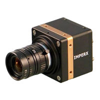
Imperx BOBCAT GEV User Manual (265 pages)
NTELLIGENT, HIGH-RESOLUTION, FIELD UPGRADEABLE, PROGRAMMABLE, 8/10/12/14 BIT DIGITAL CAMERAS
Brand:
Imperx
| Category:
Digital Camera
| Size: 8.14 MB
Table of Contents
Digital Cameras
1
Revision History
2
Table of Contents
3
Chapter 1 - Introduction
18
Bobcat Family
19
General Description
21
Bobcat Specifications
23
General Information
23
Figure 1.0A - Interline CCD Pixel Structure
24
Figure 1.0B - Kodak TRUESENSE Color Filter Interline CCD Pixel Structure
24
Spectral Response
26
Figure 1.1A - KAI (Kodak) CCD Typical Mono Spectral Response
26
Figure 1.1B - KAI (Kodak) CCD Typical UV Spectral Response
26
Figure 1.1C - KAI (Kodak) CCD Typical Color Spectral Response
27
Figure 1.1D - KODAK TRUESENSE CCD Typical Spectral Response with AR Coated Cover Glass
27
Figure 1.2A - ICX (SONY) CCD Typical Mono Spectral Response
28
Figure 1.2B - ICX (Sony) CCD Typical Color Spectral Response
28
Bayer and TRUESENSE Pattern Information
29
Figure 1.3 - Bayer Pattern Arrangement
29
Figure 1.3A - Kodak TRUESENSE Pattern Arrangement
29
Technical Specifications
30
Specifications
33
Camera Connectivity
41
Camera Link Output
41
Figure 1.4 - Camera Back Panel - Camera Link Output
41
Figure 1.5A - Camera Output Connector
42
Figure 1.4A - Camera Power Connector
44
Gige Output
46
Figure 1.6 - Camera Back Panel -Gige Output
46
Power Supply
47
MECHANICAL, OPTICAL and ENVIRONMENTAL
48
Mechanical
48
Figure 1.7A - C-Mount Camera Link Cameras
48
Figure 1.7B - C-Mount GEV Cameras
48
Figure 1.8A - C-Mount Camera Link Output - Dimensional Drawings for ICL-B0610, B0620
49
Figure 1.8B - C-Mount Camera Link Output - Dimensional Drawings for ICL-B1620
50
Figure 1.8Ba - C-Mount Camera Link Output - Dimensional Drawings for ICL-B1020, B1320
51
Figure 1.8C - F-Mount Camera Link Output - Dimensional Drawings for ICL-B2020
52
Figure 1.8Ca - F-Mount Camera Link Output - Dimensional Drawings for ICL-B3320
53
Figure 1.8Cb - F-Mount Camera Link Output - Dimensional Drawings for ICL-B3340
54
Figure 1.8Cc - F-Mount Camera Link Output - with External Heatsink Dimensional Drawings for
55
Figure 1.8D - C-Mount Gige Vision Output - Dimensional Drawings for IGV-B0610
56
Figure 1.8E - C-Mount Gige Vision Output - Dimensional Drawings for IGV-B1620
57
Figure 1.8Ea - C-Mount Gige Vision Output - Dimensional Drawings for IGV-B1020, B1320
58
Figure 1.8F - F-Mount Gige Vision Output - Dimensional Drawings for IGV-B2020
59
Figure 1.8Fa - F-Mount Gige Vision Output - Dimensional Drawings for IGV-B3320
60
Figure 1.8G - Small Bobcat Mounting Plate Using ¼ in 20 Thread
61
Figure 1.8Ga - Big Bobcat Mounting Plate Using ¼ in 20 Thread
61
Optical
62
Environmental
62
Figure 1.9A - Optical Plane Position for B0610 (KAI-0340), B0620 (KAI-0340), B1410 (ICX-285), B1610 (ICX-274), B2510 (ICX-655), and B2520 (ICX-625) Cameras
63
Figure 1.9B - Optical Plane Position for B1620 (KAI-2020) and B1920 (KAI-2093) Cameras
64
Figure 1.9C - Optical Plane Position for B2020 (KAI-04022), B4020 (KAI-11002), and
65
Figure 1.9D - Optical Plane Position for B1020 (KAI-01050, B1621 (02050), B1921 (02150
66
Figure 1.9E - Optical Plane Position (in MM) for B3320 (KAI- 08050)
67
Figure 1.9F - Optical Plane Position (MM) for B4821(KAI-16050) and B6620 (KAI-29050)
67
Chapter 2 - Camera Features
68
Image Resolution
69
Normal Mode - Single Output
69
Figure 2.1 - Single Output Mode of Operation
69
Normal Mode - Dual Output
70
Figure 2.2 - Dual Output Mode of Operation
70
Normal Mode - Quad Output
71
Figure 2.3 - Quad Output Operation
71
Center Mode
72
Figure 2.4 - Center Columns Output Mode of Operation
73
Figure 2.4 - Center Columns Output in Dual Mode of Operation
73
Figure 2.5 - Center Columns Output in Dual Tap Mode
74
Figure 2.6 - Sub-Sampled CCD Output
75
Frame Time Control
76
Internal Line and Frame Time Control
76
Camera Speed Control
76
External Line and Frame Time Control
78
Area of Interest
78
Horizontal and Vertical Window
78
Figure 2.8 - Slave Aois
79
Figure 2.9 - PAOI Enabled as Processing ROI
80
Calculating the Frame Rate Using Vertical Window
81
Figure 2.10.1A - Frame Rate Vs. Vertical Window Size for B0610
81
Figure 2.10.1B - Frame Rate Vs. Vertical Window Size for B0620
82
Dual Output
82
Figure 2.10.1C - Frame Rate Vs. Vertical Window Size for B1020
83
Congress Ave. 11/20/2012 Boca Raton, FL
83
Figure 2.10.1D - Frame Rate Vs. Vertical Window Size for B1310
84
Figure 2.10.1E - Frame Rate Vs. Vertical Window Size for B1320
85
Figure 2.10.1F - Frame Rate Vs. Vertical Window Size for B1410
86
Figure 2.10.1G - Frame Rate Vs. Vertical Window Size for B1411
87
Figure 2.10.1H - Frame Rate Vs. Vertical Window Size for B1610
88
Figure 2.10.1I - Frame Rate Vs. Vertical Window Size for B1620
89
Figure 2.10.1J - Frame Rate Vs. Vertical Window Size for B1621
90
Figure 2.10.1K - Frame Rate Vs. Vertical Window Size for B1920
91
Figure 2.10.1L - Frame Rate Vs. Vertical Window Size for B1921
92
Figure 2.11.1M - Frame Rate Vs. Vertical Window Size for B1922
93
Figure 2.12.1N - Frame Rate Vs. Vertical Window Size for B2510
94
Figure 2.10.1O - Frame Rate Vs. Vertical Window Size for B2520
95
Figure 2.10.1P - Frame Rate Vs. Vertical Window Size for B2020
96
Figure 2.10.1Q - Frame Rate Vs. Vertical Window Size for B2320
97
Figure 2.10.1R - Frame Rate Vs. Vertical Window Size for B3320
98
Figure 2.10.1S - Frame Rate Vs. Vertical Window Size for B3340
99
Figure 2.10.1T - Frame Rate Vs. Vertical Window Size for B4020
100
Figure 2.10.1U - Frame Rate Vs. Vertical Window Size for B4820
101
Figure 2.10.1V - Frame Rate Vs. Vertical Window Size for B4821
102
Figure 2.10.1W - Frame Rate Vs. Vertical Window Size for B6620
103
Figure 2.10.1X - Frame Rate Vs. Vertical Window Size for B6640
104
Binning
105
Figure 2.11 - 2:2 Horizontal and Vertical Binning
105
Figure 2.11A - AOI Within Horizontal and Vertical Binned Image
109
Exposure Control
110
Internal Exposure Control - Electronic Shutter
110
External Exposure Control
110
Variable Frame Time - Programmable Line and Frame Time
110
Figure 2.12 - Electronic Shutter Position
110
Automatic Exposure Control (AEC)
111
Figure 2.13 - Programmable Frame Time
111
Automatic Iris Control (AIC)
112
External Trigger
113
Triggering Inputs
113
Acquisition and Exposure Control
113
Trigger Strobe Control
114
Triggering Modes
114
Figure 2.14 - Standard Triggering Timing
115
Figure 2.15 - Fast Synchronized Triggering - Rapid Capture
116
Figure 2.16 - Double Exposure Triggering
117
Figure 2.17 - Frame Accumulation Triggering
118
Figure 2.18 - Asynchronous Triggering
118
Strobe Output
119
Figure 2.19 - Strobe Pulse Positioning
119
GAIN and OFFSET
120
Analog Domain - Manual Control
120
Figure 2.20 - AFE Gain and Offset
120
Digital Domain - Manual Control
121
Automatic Gain Control (AGC)
121
Data Output Format
122
Bit Depth
122
Figure 2.21 - DATA Output Format
122
Digital Data Shift
123
Output Format
123
Figure 2.22 - Output Data Using 4 Bits Digital Right Shift
123
Figure 2.24A - 2 Tap Sequential Output
124
Figure 2.24B - 2 Tap Interleaved Output
125
Figure 2.24C - 2 Tap Interleaved Output
125
Figure 2.24D - 4 Tap Interleaved Output
126
Pulse Generator
127
Figure 2.25 - Internal Pulse Generator
127
I/O Control
128
I/O Mapping
128
Electrical Connectivity
129
Figure 2.26 - IN1, IN2 Electrical Connection
129
Figure 2.27 - OUT1, OUT2 Electrical Connection
129
Test Image Patterns
131
Image Superimposition
131
White Balance and Color Conversion
132
White Balance
132
Color (Bayer to RGB) Conversion
132
Dynamic Black Level Correction and Tap Balancing
133
Black Level Correction
133
Tap Balancing
133
Transfer Function Correction - User Lut
134
Standard Gamma Correction
134
Figure 2.30 - Look up Table
134
User Defined LUT
135
Figure 2.31 - Gamma Corrected Video Signal
135
Figure 2.32 - Custom LUT
135
Defective Pixel Correction
136
Static Pixel Correction
136
Dynamic Pixel Correction
137
Flat Field Correction
138
Figure 2.33A - Original Image Showing 'Shading' Effect
139
Figure 2.33B - Flat Field Corrected Image
139
Negative Image
140
Figure 2.34 - Normal and Negative Image
140
Camera Interface
141
Status LED
141
Temperature Monitor
141
Exposure Time Monitor
141
Frame Time Monitor
142
Current Image Size
142
Chapter 3 - Digital Image Processing
143
Overview
144
Image Enhancement
144
Threshold Operation
144
Figure 3.1 - Original and Processed Image with Single Threshold
145
Figure 3.2 - Original and Processed Image with Double Threshold
145
Multi Point Correction
146
Figure 3.3 - Original and Processed Image with Threshold and Gray Scale Stretch
146
Figure 3.4 - Single Point TF Correction
147
Figure 3.5 - Multi Point TF Correction
148
Figure 3.6 - Multi Point Image Correction (a - Original, B - Processed)
149
Chapter 4 - Camera Configuration
150
Overview
151
Camera Configuration
151
Configuration Memory - Parameter FLASH
151
Camera Serial Protocol
152
Figure 4.1 - Serial Protocol Format
152
Figure 4.2 - Normal Write Cycle
153
Figure 4.3A - Invalid Command Error
153
Figure 4.3B - Rx Timeout Error
153
Error Code
153
Figure 4.4 - Normal Read Cycle
154
Camera Configuration Register Description
156
Startup Procedure
156
Saving and Restoring Settings
156
Retrieving Manufacturing Data
158
Camera Information Registers
160
Image Size (AOI) Workspace Registers
162
Exposure Control Workspace Registers
169
AEC, AGC, AIC Workspace Registers
170
Video Amp, Gain and Offset Workspace Registers
173
Triggering Workspace Registers
176
Pulse Generator Workspace Registers
179
Test Pattern Workspace Registers
180
Input/Output Workspace Registers
181
Output Data Format
186
White Balance Workspace Registers
188
Color Conversion Workspace Registers
189
Data Correction Workspace Registers
190
Data Processing Register Description
191
Image Enhancement Workspace Registers
191
Chapter 5 - Configurator for Cameralink
194
Overview
195
Discovery Procedure
195
Figure 5.1 - Discovery Procedure - Select Port
195
Graphical User Interface
196
Figure 5.2 - Camconfig GUI Advanced
196
Figure 5.2A - Camconfig GUI Basic
197
Main Gui Menu
198
Figure 5.3 - Main Menu
198
Figure 5.5 - Command Terminal
200
Figure 5.6 - Download Terminal
201
View Gui Windows
202
Figure 5.7 - View GUI Windows
202
Gui Help
203
Figure 5.8 - Help Menu
203
Figure 5.9 - about Camconfig
203
Parameter Windows
204
Video Amp
204
Figure 5.10 - Video Amp Parameter Window
204
I/O Control
205
Trigger
206
Figure 5.11 - I/O Control Parameter Window
206
Pulse Generator
209
Figure 5.13 - Pulse Generator Window
209
Exposure
210
Test Image
212
Area of Interest (AOI)
213
Figure 5.16 - AOI Window
214
Strobe Control
215
Figure 5.17 - Strobe Control Window
215
Color
216
Processing
217
Figure 5.18 - Color Window
217
Data Output
220
Figure 5.20 - Data Output Window
220
Chapter 6 - Gen<I>Cam Reference Manual
222
Introduction
223
Node Tree
224
Device Information
224
IP Engine
224
Gige Vision Transport Layer
224
Congress Ave. 11/20/2012 Boca Raton, FL
225
Acquisition and Trigger Controls
226
Counters and Timers Controls
226
Analog Controls
227
Test Mode
227
User Sets
227
Custom Features
228
Chapter 7 - Bobcat Warranty and Support
231
Ordering Information
232
Technical Support
233
Warranty
234
Appendix A - Camera Configuration Reference
235
Abbreviations
236
Saving and Restoring Registers
236
Camera Information Registers
236
A.0 Abbreviations
236
A.1 Saving and Restoring Registers
236
A.2 Camera Information Registers
236
Image Size (Aoi) Registers
237
Exposure Control Registers
238
Video Registers
238
A.5 Video Registers
238
Aec, Agc, Aic Registers
239
Trigger Registers
239
A.7 Trigger Registers
239
Pulse Generator Registers
240
Test Pattern Registers
240
Strobe Registers
240
Input and Output Registers
241
Output Data Format Registers
241
Wb and Color Correction Registers
241
Data Correction Registers
242
Processing Registers
242
Manufacturing Data Registers
242
Appendix B - Creating Look up Tables
243
Overview
244
Using an Ascii Text Editor
244
B.1 Overview
244
B.2 Using an Ascii Text Editor
244
Using Microsoft Excel
245
Appendix C - Creating Dpc and Hpc Tables
246
Overview
247
Using an Ascii Text Editor
247
C.1 Overview
247
C.2 Using an Ascii Text Editor
247
Appendix D - Software Installation - Cl
248
Appendix E - Firmware Upgrade - Cl
250
Overview
251
Bobcat Upgrade
251
E.1 Overview
251
E.2 Bobcat Upgrade
251
Appendix F - Gige Vision Firmware Upgrade
255
Overview
256
RGS Upgrade
259
IP Engine Install
260
Appendix G - Power Supplies
262
Congress Ave. 11/20/2012 Boca Raton, FL
263
Congress Ave. 11/20/2012 Boca Raton, FL
264
Advertisement
Advertisement
Related Products
Imperx bobcat hd-sdi
Imperx bobcat
Imperx BOBCAT CameraLink PoCL
Imperx BOBCAT CoaXPress
Imperx BOBCAT HD-SDI Series
Imperx BOBCAT B0610M
Imperx BOBCAT B1411M
Imperx BOBCAT B1921T
Imperx BOBCAT B1943C
Imperx BOBCAT B1943T
Imperx Categories
Digital Camera
Security Camera
Color Camera
Computer Hardware
PCI Card
More Imperx Manuals
Login
Sign In
OR
Sign in with Facebook
Sign in with Google
Upload manual
Upload from disk
Upload from URL