Sign In
Upload
Manuals
Brands
IMES Manuals
Measuring Instruments
EPM-XPplus
IMES EPM-XPplus Manuals
Manuals and User Guides for IMES EPM-XPplus. We have
3
IMES EPM-XPplus manuals available for free PDF download: Original Operating Instructions, Original Operating Instruction, Operation Manual
IMES EPM-XPplus Original Operating Instructions (70 pages)
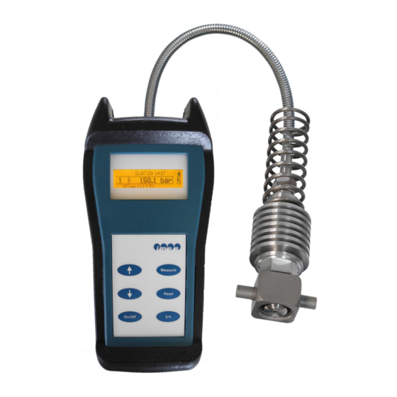
Electronic Analyser
Brand:
IMES
| Category:
Measuring Instruments
| Size: 5 MB
Table of Contents
Contents
4
Table of Contents
4
List of Figures
6
1 Important Information
9
Use of the Operator Manual
9
Copyright
9
Warning Notices
9
Address of the Manufacturer
10
Obligations of the Operator
11
2 Safety
11
Intended Use
11
Personnel Requirements
12
Safety Notes
12
3 Transportation and Packaging
12
Safety Notes for Transportation
12
Scope of Delivery
13
Packaging
13
4 Technical Data
13
Dimensions and Weight of Instrument Case
13
Other Parameters
13
Plus Unit
13
Table 1: Dimensions and Weight
13
Table 2: Technical Specification
13
5 Scope of Supply
14
6 Description
14
Introduction
14
Measure Functions
15
Functional Description
15
7 Operation
15
Operator Push Buttons
15
Figure 2: Push Buttons
15
Operating Functions
16
Install Rechargeable Batteries
17
Figure 3: 4 Pcs. Re-Chargeable Battery in the Transport Case
17
Figure 4: Back Side of EPM-XP Incl. Protection Cover
17
Figure 5: Battery Case
17
Table 3: Functions of Push Buttons
17
Confirm Installed Battery Type
18
Figure 6: Battery Holder
18
Figure 7: 4 X Nimh AAA 930 Mah Installed on Battery Holder
18
Figure 8: Selection of Installed Battery Type
18
Install Batteries to Correct Pole
18
Charge Battery
19
Measurements with EPM-XP
19
Figure 9: Indication During Charging Process
19
Figure 10: Indication Charging Process Completed
19
Figure 11: Indicator Cock
19
Figure 12: Adaptor Installed on Indicator Cock
19
Figure 13: Indication of 2-Stroke Mode
19
Figure 14: Indication of 4-Stroke Mode
19
Figure 15: Warming up Sensor
20
Figure 16: Indication During Measurement
20
Figure 17: Indication of Measurement Results on Display for 3S
20
Figure 18: Indication over Temperature on Measuring Cell of Sensor
20
8 Installation of Visualisation- and USB Driver Software
21
Figure 19: Dialog of Installation
21
Figure 20: Select Destination Location
21
Figure 21: Start Menu Folder
22
Figure 22: Select Additional Tasks
22
Figure 23: Ready to Install
22
Figure 24: Ready to Install
23
Figure 25: Installation Completed
23
9 Visualization Software
24
The Application Window
24
Figure 26: Start up Window of EPM-XP
24
Connecting to the EPM-XP
25
Plus Device
25
Figure 27: EPM- XP
25
Figure 28: Connect Button
25
Figure 29: Connect Button with Connection Established
25
Download Measured Data to PC
26
Figure 30: Selection of Engine Configuration
26
Figure 31: Entering of Specific Engine Data
26
Open Saved Data
27
Figure 32: Selection of Directory on Hard Disc of PC for Saving Data
27
Figure 33: Downloading and TDC Calculation Process of Measured Data
27
Figure 34: Button "Open
27
Figure 35: Stored Measurement File
27
Visualization of Measured Data on PC
28
Figure 36: File View
28
Figure 37: Cylinder Selection Panel
28
Figure 38: Cylinder Details Panel
29
Figure 39: Display Mode Panel
29
Figure 40: Zoom in
29
Figure 41: Zoom out
30
Figure 42: Functions of P/Alpha Diagram
30
P/Alpha Diagram
30
Figure 43: Pressure Curve Adjustments
31
Figure 44: P/Volume Diagram
32
Figure 45: P/Volume (Log) Diagram
32
P/Volume (Logarithmic)
32
P/Volume Diagram
32
Engine Report
33
Figure 46: Engine Report Diagram
33
Balance Diagrams
34
Figure 47: Engine Report Configuration Dialog
34
Figure 48: Balance Diagram
34
Figure 49: Overview of Bush Puttons
35
Figure 50: Selection Criteria for Measurement Files
35
Figure 51: Selection of Measurement Files
35
Trending
35
Figure 52: Selection Criteria for Values and Cylinder
36
Figure 53: Display of Trending Function
36
Change Engine Data
37
Figure 54: File Entry in Menu Bar
37
Figure 55: CSV File Selection
37
Figure 56: Engine Configuration Dialog
37
Save to ASCII Format
37
Engine Database Editor
38
Figure 57: Engine Database Editor
38
Figure 58: Installation Template Editor
38
Installation Template Editor
38
Color Setup
39
Figure 59: Engine Configuration Dialog
39
Figure 60: "Solver Configuration" Dialog
39
Figure 61: "Color Setup" Dialog
39
Solver Configuration
39
Figure 62: Cylinder Pressure Curve Incl. Motored Curve
40
Figure 63: Shifted Cylinder Pressure Curve Incl. Motored Curve
40
Optimize TDC Calculation
40
Figure 64: Button "Save REF
41
Figure 65: Save the Reference on Hard Disc of PC
41
Figure 66: Button "Open REF
41
Figure 67: Selection of Reference Curve on Hard Disc of PC
41
Open a Reference File
41
Save as Reference Curve
41
Delete Measurements on EPM-XP Plus
42
Figure 68: Display of Selected Reference Curve in Comparison to a Cylinder Curve
42
Figure 69: Close Reference Curve
42
Figure 70: Button "Del.meas
42
Online Measurements on Engines with EPM-XP
43
Preparation of EPM-Xpplus for Online Measurements on 2-Stroke Engines
43
Figure 71: Indicator Cock
43
Figure 72: Adaptor Installed on Indicator Cock
43
Figure 73: EPM-XP Connected to Notebook
43
Preparation of EPM-Xpplus for Online Measurements on 4-Stroke Engines
44
Figure 74: Disconnection of Spring
44
Figure 75: Disconnection of Sensor from Adaptor
44
Figure 76: Connection of HTT-04 Sensor on Special Cooling Adaptor
44
Figure 77: Indicator Cock
45
Figure 78: Adaptor Installed on Indicator Cock
45
Figure 79: EPM-XP Connected Via USB Cable to Notebook
45
Preparation of EPM-Xpplus for Online Measurements Via Ethernet Cable
46
Figure 80: Overview of Online Measurement with EPM-XP
46
Figure 81: Overview of Ethernet Connection to EPM-XP
46
Visualization Software
47
Figure 82: Indication on Display for Successful Connection to PC
47
Figure 83: Connect Button
47
Figure 84: Connect Button with Connection Established
47
Screen Page "Online
48
Figure 85: Indication of Online Pressure Curve
48
Figure 86: Example for over Temperature on Measuring Cell of Sensor
48
Figure 87: Button "Pressure Curve Save
49
Figure 88: Register for Saving the File
49
Figure 89: Indication of Online Pressure Curve During Saving Process
50
Figure 90: Button "Working Cycle Save
50
Figure 91: Indication of Online Pmax Data
51
Figure 92: Record Button
51
Figure 93: Register for Saving the File
51
Figure 94: Indication of Pmax Data During Recording Process
52
Figure 95: Example for over Temperature on Measuring Cell of Sensor
52
Screen Page "Offline
53
Figure 96: Screen Page "Offline
53
Figure 97: Button "100 Pressure Curve Open
53
Figure 98: Register of Saved File
53
Figure 99: Indication of Pressure Cycles
54
Figure 100: Button "Working Cycle Open
54
Figure 101: Screen Page "Working Cycle Offline
54
Figure 102: Register of Saved Working Cycle Data File
55
Figure 103: Selection of Saved Pmax Working Cycle
55
Figure 104: Indication of Selected Pmax Data
55
Update Firmware to EPM-XP from Visualisation Software
56
Check Actual Firmware Version
56
Figure 105: Button "Connect
56
Figure 106: Selection "Tools
56
Figure 107: Selection "Firmware
56
Figure 108: Load-And Update Firmware
56
Figure 109: Indication of Main Menu
56
10 Accuracy Check
57
Figure 110: Indication of Device Info
57
Figure 111: Indication of Actual Firmware
57
Figure 112: Calibration Certificate of EPM-XP
57
Check on Pressure Calibrator
58
Figure 113: Thompson Adaptor Mounted on Pressure Plate
58
Figure 114: Example for Indication of Static Pressure @ 0 Bar
58
Figure 115: Example for Indication of Static Pressure @ 50 Bar
59
Figure 116: Indication of Main Menu
59
Figure 117: Indication of Measuring Mode
59
Figure 118: Indication of Sensor Test
59
Figure 119: Indication @ 0 Bar on Display
59
Example of Static Pressure Indication
60
Figure 120: Indication @ 50 Bar
60
Figure 121: Indication on Pressure Pump
60
Table 4: Static Pressure Comparison
60
11 Cleaning
61
Periodically Cleaning
61
Cleaning in Case of Hard Deposit
61
Figure 122: Periodical Cleaning of Gas Channel
61
Figure 123: Disconnection of Spring
61
Figure 124: Disconnection of Sensor from Adaptor
61
Cleaning Procedure of Adaptor
62
Cleaning Procedure of Cylinder Pressure Sensor
62
Figure 125: Drill 2.5 MM
62
Figure 126: Drill in Gas Channel of Adaptor for Cleaning
62
Figure 127: Special Drill Tool
62
Figure 128: Special Drill Tool in Gas Channel of Sensor
62
12 Basic Check for Fault Finding
63
13 Nomenclature
63
Table 5: Basic Check for Fault Finding
63
Table 6: Nomenclature
63
14 Option ______________________________________________________________
64
IMES IPE Performance Evaluation Software
64
Figure 129: Example IPE Software
64
Ethernet Cable 20M
65
Figure 130: Ethernet Cable
65
USB Extender for Connection to Ethernet Cable
66
Figure 131: USB-Ethernet Extender
66
Thompson Adaptor for 4-Stroke Continuous Online Measurement
67
Figure 132: Thompson Adaptor for 4-Stroke Online Measurement
67
Pressure Pump Coupling for Thompson Adaptor
68
Figure 133: Pressure Pump Coupling
68
Thread Cleaner for Thompson Thread
69
Figure 134: Thread Cleaner for Thompson Thread
69
15 EU Declaration of Conformity
70
Advertisement
IMES EPM-XPplus Original Operating Instruction (66 pages)
Electronic Analyser
Brand:
IMES
| Category:
Measuring Instruments
| Size: 10 MB
Table of Contents
Table of Contents
4
List of Figures
5
1 Important Information
9
Use of the Operator Manual
9
Copyright
9
Warning Notices
9
Address of the Manufacturer
10
Obligations of the Operator
11
2 Safety
11
Intended Use
11
Personnel Requirements
12
Safety Notes
12
3 Transportation and Packaging
12
Safety Notes for Transportation
12
Scope of Delivery
13
Packaging
13
4 Technical Data
13
Dimensions and Weight of Instrument Case
13
Other Parameters
13
Table 1: Dimensions and Weight
13
Table 2: Technical Specification
13
5 Scope of Supply
14
6 Description
14
Introduction
14
Measure Functions
15
Functional Description
15
7 Operation
15
Operator Push Buttons
15
Figure 2: Push Buttons
15
Operating Functions
16
Install Rechargeable Batteries
17
Figure 3: 4 Pcs. Re-Chargeable Battery in the Transport Case
17
Figure 4: Back Side of EPM-XP Incl. Protection Cover Figure 5: Battery Case
17
Table 3: Functions of Push Buttons
17
Confirm Installed Battery Type
18
Figure 6: Battery Holder
18
Figure 7: 4 X Nimh AAA 930 Mah Installed on Battery Holder
18
Figure 8: Selection of Installed Battery Type
18
Install Batteries to Correct Pole
18
Charge Battery
19
Measurements with EPM-XP
19
Figure 9: Indication During Charging Process
19
Figure 10: Indication Charging Process Completed
19
Figure 11: Indicator Cock Figure 12: Adaptor Installed on Indicator Cock
19
Figure 13: Indication of 2-Stroke Mode Figure 14: Indication of 4-Stroke Mode
19
Figure 15: Warming up Sensor Figure 16: Indication During Measurement
20
Figure 17: Indication of Measurement Results on Display for 3S
20
Figure 18: Indication over Temperature on Measuring Cell of Sensor
20
8 Installation of Visualisation- and USB Driver Software
21
Figure 19: Dialog of Installation
21
Figure 20: Select Destination Location
21
Figure 21: Start Menu Folder
22
Figure 22: Select Additional Tasks
22
Figure 23: Ready to Install
22
Figure 24: Ready to Install
23
Figure 25: Installation Completed
23
9 Visualisation Software Release 1.2.4.0
24
Screen Page "File" Start up Window
24
Screen Page "File
24
Figure 26: EPM- XP
24
Figure 27: Start up Window of EPM-XP
24
Download Measured Data to PC
25
Figure 28: EPM-XP
25
Figure 29: Selection of Engine Configuration
25
Figure 30: Entering of Specific Engine Data
25
Figure 31: Selection of Directory on Hard Disc of PC for Saving Data
26
Figure 32: Downloading and Optimization Process of Measured Data
26
Visualisation of Measured Data on PC
27
P/Alpha Diagram
27
Figure 33: P/Alpha Diagram
27
Figure 34: Functions of P/Alpha Diagram
27
P/Volume Diagram
28
Figure 35: Cursor Line Functions of P/Alpha Diagram
28
Figure 36: P/Volume Diagram
28
Open Saved Data
29
Figure 37: P/Volume (Log) Diagram
29
Figure 38: Button "Open
29
Figure 39: Stored Measurement File
29
Balance Diagrams
30
Figure 40: Information about Cylinder During Uploading Process
30
Figure 41: Balance Diagram
30
Engine Report
31
Figure 42: Engine Report Diagram
31
Figure 43: Overview of Bush Puttons
31
Figure 44: Selection Criteria for Measurement Files
31
Figure 45: Selection of Measurement Files
32
Figure 46: Selection Criteria for Values and Cylinder
32
Save to ASCII Format
33
Figure 47: Display of Trending Function
33
Figure 48: Tools
33
Figure 49: CSV
33
Figure 50: CSV File Selection
33
Change "Engine Settings
34
Solver Configuration
34
Figure 51: Selection Field
34
Figure 52: "Engine Settings
34
Figure 53: "Motor Data
34
Figure 54: "Options
34
Figure 55: "Options
34
Optimize TDC Calculation
35
Figure 56: Cylinder Pressure Curve Incl. Motored Curve
35
Figure 57: Shifted Cylinder Pressure Curve Incl. Motored Curve
35
Save as Reference File
36
Open a Reference File
36
Figure 58: Button "Save REF
36
Figure 59: Save the Reference on Hard Disc of PC
36
Figure 60: Button "Open REF
36
Figure 61: Selection of Reference Curve on Hard Disc of PC
36
Delete Measurements on EPM-XP
37
Figure 62: Display of Selected Reference Curve in Comparison to a Cylinder Curve
37
Figure 63: Close Reference Curve
37
Figure 64: Button "Del.meas
37
Online Measurements on Engines with EPM-XP
38
Preparation of EPM-Xpplus for Online Measurements on 2-Stroke Engines
38
Figure 65: Indicator Cock Figure 66: Adaptor Installed on Indicator Cock
38
Figure 67: EPM-XP Connected to Notebook
38
Preparation of EPM-Xpplus for Online Measurements on 4-Stroke Engines
39
Figure 68: Disconnection of Spring Figure 69: Disconnection of Sensor from Adaptor
39
Figure 70: Connection of HTT-04 Sensor on Special Cooling Adaptor
39
Figure 71: Indicator Cock Figure 72: Adaptor Installed on Indicator Cock
40
Figure 73: EPM-XP Connected Via USB Cable to Notebook
40
Preparation of EPM-Xpplus for Online Measurements Via Ethernet Cable
41
Figure 74: Overview of Online Measurement with EPM-XP
41
Figure 75: Overview of Ethernet Connection to EPM-XP
41
Figure 76: Indication on Display for Successful Connection to PC
42
Figure 77: Start up Window of EPM-XP
42
Screen Page "Online
43
Figure 78: EPM-XP
43
Figure 79: Indication of Online Pressure Curve
43
Figure 80: Online Pressure Curve Manual Shifted by Arrow Function
44
Figure 81: Example for over Temperature on Measuring Cell of Sensor
44
Figure 82: Button "Pressure Curve Save
45
Figure 83: Register for Saving the File
45
Figure 84: Indication of Online Pressure Curve During Saving Process
46
Figure 85: Button "Working Cycle Save
46
Figure 86: Register for Saving the File
46
Figure 87: Indication of Online Pmax Data
47
Figure 88: Indication of Pmax Data During Recording Process
47
Screen Page "Offline
48
Figure 89: Example for over Temperature on Measuring Cell of Sensor
48
Figure 90: Screen Page "Offline
48
Figure 91: Button "100 Pressure Curve Open
49
Figure 92: Register of Saved File
49
Figure 93: Indication of Pressure Cycles
49
Figure 94: Button "Working Cycle Open
50
Figure 95: Screen Page "Working Cycle Offline
50
Figure 96: Register of Saved Working Cycle Data File
50
Figure 97: Selection of Saved Pmax Working Cycle
51
Figure 98: Indication of Selected Pmax Data
51
Update Firmware to EPM-XP
52
Check Actual Firmware Version
52
Figure 99: Button "Connect" Figure 100: Selection "Tools
52
Figure 101: Selection "Firmware" Figure 102: Load-And Update Firmware
52
Figure 103: Indication of Main Menu
52
Figure 104: Indication of Device Info
52
10 Accuracy Check
53
Figure 105: Indication of Actual Firmware
53
Figure 106: Calibration Certificate of EPM-XP
53
Check on Pressure Calibrator
54
Figure 107: Thompson Adaptor Mounted on Pressure Plate
54
Figure 108: Example for Indication of Static Pressure @ 0 Bar
54
Figure 109: Example for Indication of Static Pressure @ 50 Bar
55
Figure 110: Indication of Main Menu
55
Figure 111: Indication of Measuring Mode
55
Figure 112: Indication of Sensor Test
55
Figure 113: Indication @ 0 Bar on Display
55
Example of Static Pressure Indication
56
Figure 114: Indication @ 50 Bar Figure 115: Indication on Pressure Pump
56
Table 4: Static Pressure Comparison
56
11 Cleaning ____________________________________________________________
57
Periodically Cleaning
57
Cleaning in Case of Hard Deposit
57
Figure 116: Periodical Cleaning of Gas Channel
57
Cleaning Procedure of Adaptor
58
Cleaning Procedure of Cylinder Pressure Sensor
58
Figure 119: Drill 2.5 MM Figure 120: Drill in Gas Channel of Adaptor for Cleaning
58
12 Basic Check for Fault Finding
59
Table 5: Basic Check for Fault Finding
59
Table 6: Nomenclature
59
13 Nomenclature ________________________________________________________ 59
60
IMES IPE Performance Evaluation Software
60
Figure 123: Example IPE Software
60
Ethernet Cable 20M
61
Figure 124: Ethernet Cable
61
USB Extender for Connection to Ethernet Cable
62
Figure 125: USB-Ethernet Extender
62
Thompson Adaptor for 4-Stroke Continuous Online Measurement
63
Figure 126: Thompson Adaptor for 4-Stroke Online Measurement
63
Pressure Pump Coupling for Thompson Adaptor
64
Figure 127: Pressure Pump Coupling
64
Thread Cleaner for Thompson Thread
65
Figure 128: Thread Cleaner for Thompson Thread
65
14 Option______________________________________________________________
60
15 EU Declaration of Conformity
66
IMES EPM-XPplus Operation Manual (48 pages)
Brand:
IMES
| Category:
Measuring Instruments
| Size: 2 MB
Table of Contents
Table of Contents
3
Copyright
6
Warning Notices
6
Address of the Manufacturer
7
Safety
8
Intended Use
8
Personnel Requirements
8
Important Information
6
Use of the Operator Manual
6
Plus Device
8
Obligations of the Operator
9
Transportation
10
Scope of Supply
11
Figure 1: EPM-XP Plus Device Incl.all Components in Instrument Case
11
Safety Notes
8
Plus Device
11
Packaging
12
Unpacking Inspection
12
Technical Data
13
Dimensions and Weight of Instrument Case
13
Other Parameters
13
Table 1: Dimensions and Weight
13
Table 2: Technical Specification
13
Introduction
14
Device Overview
15
EPM-XP Plus Device Operation
15
Figure 2: Push Buttons
16
Operator Push Buttons
16
Table 3: Standard Button Functions
16
Switch On/Off
17
Using the EPM-XP Plus Device
17
Making Measurements with the EPM-XP
17
Figure 3: Boot Screen
17
Figure 4: Measure Dialog
17
Figure 5: Power off
17
Figure 6: Indication 2-Stroke and 4-Stroke Setting
18
Figure 7: Indicator Valve
18
Figure 8: Adapter Installed on Indicator Valve
19
Figure 9: Device Display with Cylinder Pressure
19
Figure 10: Warming up Sensor
19
Viewing Stored Measurement Data
20
Data Transfer to EPM Visualization Software
20
Figure 11: Indication During Measurement
20
Figure 12: Indication of over Temperature on Measuring Cell of Sensor
20
Figure 13: Read Display
20
Figure 14: EPM-XP Plus Connected Via USB Cable to PC
21
Figure 15: Measure Dialog with Pressure Applied
22
Function Reference
22
Measurement Mode
22
Modes of Operation
22
Keyboard Button Functions in Measurement Mode
23
Starting Measurements
23
Figure 16: Measure Dialog Without Pressure Applied
23
Figure 17: Data Recording Progress Display
23
Table 4: Button Functions in Measurement Mode
23
Menu Functions in Measurement Mode
24
Read Mode
24
Figure 18: READ Dialog after Measurement
24
Keyboard Button Functions in READ Mode
25
Menu Functions in READ Mode
25
Figure 19: Measure Dialog with Pressure Applied
25
Figure 20: READ Functions Menu
25
Table 5: Keyboard Button Functions in READ Mode
25
Clear Data
26
Engine Selection
26
Engine Selection Menu
26
Figure 21: Engine Number Indication in Display
26
Figure 22: Engine Number Selection in Menu
26
Figure 23: Engine Selection Menu
26
Clear Data for Engine
27
Device Configuration
27
Figure 24: Clear Engine Data
27
Figure 25: Setup Menu
27
Online Measurements
28
Online Measurements with EPM-XP
28
Plus Device
28
Figure 26: Indicator Valve
29
Figure 27: Adapter Installed on Indicator Port
29
Cooling Thompson Adapter for Online Measurements on 4-Stroke Engines
30
Figure 28: Removal of Spring
30
Figure 29: Dismounting of Sensor from Adapter
30
Figure 30: Mounting of Sensor on Special Cooling Adapter
31
Battery Installation
32
Battery Insertion and Replacement
32
Figure 31: 4 Pcs. Re-Chargeable Battery in the Transport Case
32
Figure 32: Back Side of EPM-XP
32
Figure 33: Battery Case
33
Figure 34: Battery Holder
33
Figure 35: Batteries Installed on Battery Holder
33
Battery Charging
34
Battery Level Indication
34
Figure 36: Selection of Installed Battery Type
34
Figure 37: Indication During Charging Process
34
Figure 38: Battery Level Indication
34
Automatic Power off
35
Firmware Update
35
Check Actual Firmware Version
35
Figure 39: Setup Menu
35
Figure 40: Indication of Device Info
35
Figure 41: Indication of Actual Firmware
35
Function Upgrade
36
Table 6: EPM Device Variants Function Scopes
36
Accuracy Check
37
Check on Pressure Calibrator
37
Figure 42: Calibration Certificate of EPM-XP
37
Figure 43: Thompson Adapter Mounted on Pressure Plate
38
Figure 44: Example for Indication of Static Pressure @ 0 Bar
38
Figure 45: Example for Indication of Static Pressure @ 50 Bar
38
Cleaning
40
Example of Static Pressure Indication
40
Figure 46: Periodical Cleaning of Gas Channel
40
Periodically Cleaning
40
Table 7: Example of Static Pressure Comparison
40
Cleaning in Case of Hard Deposit
41
Cleaning Procedure of Adapter
41
Figure 47: Disconnection of Spring
41
Figure 48: Disconnection of Sensor from Adapter
41
Figure 49: Drill 2.5 MM
41
Cleaning Procedure of Cylinder Pressure Sensor
42
Figure 50: Drill in Gas Channel of Adapter for Cleaning
42
Figure 51: Special Drill Tool
42
Figure 52: Special Drill Tool in Gas Channel of Sensor
42
Basic Check for Fault Finding
43
Nomenclature
43
Table 8: Basic Check for Fault Finding
43
Table 9: Nomenclature
43
Options
44
Description
44
Figure 53: USB Extender with Ethernet Cable
44
Figure 54: Application of USB-Extender
44
USB Extender Set with 20 M Ethernet Cable
44
Figure 55: Overview of USB Connection with USB Extender to EPM-XP
45
Figure 56: Indication of Successful USB Connection
45
Figure 57: Thompson Adapter for 4-Stroke Online Measurement
46
Thompson Adapter for 4-Stroke Continuous Online Measurement
46
Pressure Pump Coupling for Thompson Adapter
47
Usage
45
Figure 58: Pressure Pump Coupling
47
Figure 59: Thread Cleaner for Thompson Thread
47
Thread Cleaner for Thompson Thread
47
EU Declaration of Conformity
48
Advertisement
Advertisement
Related Products
IMES EPM-XP
IMES EPM-Peak
IMES Categories
Measuring Instruments
Monitor
Receiver
Touch Panel
More IMES Manuals
Login
Sign In
OR
Sign in with Facebook
Sign in with Google
Upload manual
Upload from disk
Upload from URL