IMES EPM-XP plus Operation Manual
Hide thumbs
Also See for EPM-XP plus:
- Original operating instructions (70 pages) ,
- Original operating instruction (66 pages)

Related Manuals for IMES EPM-XP plus


Summary of Contents for IMES EPM-XP plus
- Page 1 Operation Manual EPM-XPplus Firmware 2.04 - 2023-06-26 Operation Manual EPM-XP plus 1 of 48...
- Page 2 For further information about other IMES products, please visit our website: www.imes.de Copyright Copyright © 2023 IMES GmbH. All rights reserved. All data is for information only and not guaranteed for legal purposes. Information has been carefully checked, however, no responsibility is assumed for inaccuracies.
-
Page 3: Table Of Contents
Operation Manual EPM-XPplus Firmware 2.04 - 2023-06-26 Table of contents 1 Important information........................6 1.1 Use of the operator manual......................6 1.2 Copyright............................6 1.3 Warning Notices.........................6 1.4 Address of the manufacturer......................7 2 Safety..............................8 2.1 Intended use..........................8 2.2 Personnel requirements......................8 2.3 Safety notes..........................8 2.4 Obligations of the operator......................9 2.5 Transportation..........................10 3 Scope of supply..........................11... - Page 4 Operation Manual EPM-XPplus Firmware 2.04 - 2023-06-26 8.3 Battery level indication......................34 8.4 Automatic Power Off........................35 9 Firmware update..........................35 9.1 Check actual firmware version....................35 10 Function upgrade..........................36 11 Accuracy check..........................37 11.1 Check on pressure calibrator....................37 11.2 Example of static pressure indication..................40 12 Cleaning............................40 12.1 Periodically cleaning.......................40 12.2 Cleaning in case of hard deposit.....................41...
- Page 5 Operation Manual EPM-XPplus Firmware 2.04 - 2023-06-26 Figure 24: Clear engine data ......................... 27 Figure 25: Setup menu .......................... 27 Figure 26: Indicator valve ........................29 Figure 27: Adapter installed on indicator port ..................29 Figure 28: Removal of spring ........................ 30 Figure 29: Dismounting of sensor from adapter ...................
-
Page 6: Important Information
1.2 Copyright These operating instructions has to be treated confidentially. They may only be used by the persons authorized to this effect. They may only be given to third parties with the written consent of IMES GmbH. All documents are protected under copyright law. -
Page 7: Address Of The Manufacturer
INFO Text of the note … A note identifies additional information that facilitates the handling of the device. 1.4 Address of the manufacturer IMES GmbH Dr.-Herbert-Kittel-Str. 2 87600 Kaufbeuren Germany Tel.: + 49 8341 966173 0... -
Page 8: Safety
Operation Manual EPM-XPplus Firmware 2.04 - 2023-06-26 2 Safety 2.1 Intended use WARNING Risk of injury due to non-intended use. The EPM-XP plus device may be a source of danger if operated not in compliance with the intended use and/or being used otherwise. Use the EPM-XP plus device for its intended purpose only. -
Page 9: Obligations Of The Operator
The operator is obliged to operate the EPM-XP plus device only in proper condition. Hazard areas arising between IMES devices and customer equipment are to be secured by the operator. The operator must designate and instruct responsible persons: Only employ trained or instructed personnel. -
Page 10: Transportation
Operation Manual EPM-XPplus Firmware 2.04 - 2023-06-26 2.5 Transportation CAUTION Property damage due to improper transportation! Improper transportation may cause property damage. During unloading of packing pieces upon delivery and during internal • transportation proceed with care, do not let the packing pieces fall. Do not subject the device to any hard shocks and protect it against all •... -
Page 11: Scope Of Supply
Operation Manual EPM-XPplus Firmware 2.04 - 2023-06-26 3 Scope of supply Figure 1: EPM-XP plus device incl.all components in instrument case The scope of supply includes the following components: plus EPM-XP device with cylinder pressure sensor mounted on Thompson adapter •... -
Page 12: Unpacking Inspection
3.2 Packaging Unless an agreement was made with IMES GmbH regarding the return of the packaging material, the packaging material remains with the customer. The most commonly used packaging materials cardboard. -
Page 13: Technical Data
Operation Manual EPM-XPplus Firmware 2.04 - 2023-06-26 4 Technical data 4.1 Dimensions and weight of instrument case Length: Width: Height: Weight of instrument case Table 1: Dimensions and weight 4.2 Other parameters Measuring range 0...300 bar plus ® Accuracy ( EPM-XP device incl. -
Page 14: Introduction
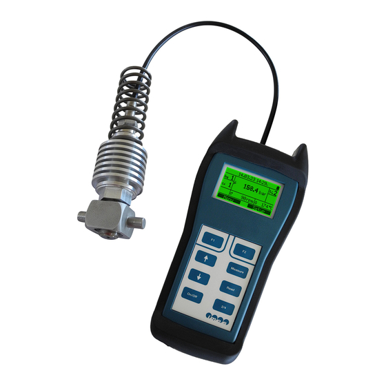
Operation Manual EPM-XPplus Firmware 2.04 - 2023-06-26 5 Introduction plus The EPM-XP electronic indicator is a handy-, battery powered-, portable device to measure and evaluate cylinder pressure on 2- and 4-stroke diesel and gas engines at speed up to 1800 RPM. The device is equipped with a high temperature pressure sensor and a Thompson adapter for direct measurement of cylinder pressure on common indicator ports of medium and large size engines. -
Page 15: Epm-Xp Plus Device Operation
Operation Manual EPM-XPplus Firmware 2.04 - 2023-06-26 plus 6 EPM-XP Device Operation 6.1 Device overview 1. Display 2. Keyboard 3. USB connector 15 of 48... -
Page 16: Operator Push Buttons
Operation Manual EPM-XPplus Firmware 2.04 - 2023-06-26 6.2 Operator push buttons The device operation is controlled by the 8 push buttons (Figure 2) at the bottom of the front side. Figure 2: Push buttons Button Standard function Switch device on and off Function mode dependent. -
Page 17: Switch On/Off
Operation Manual EPM-XPplus Firmware 2.04 - 2023-06-26 6.3 Switch On/Off To switch the device on, press the button until the display is lightened. After power up the device shows the following information about the device and the current engine configuration. Figure 3: Boot screen At the end of the startup process the device will enter the measuring mode and display the measure dialog:... -
Page 18: Figure 6: Indication 2-Stroke And 4-Stroke Setting
Operation Manual EPM-XPplus Firmware 2.04 - 2023-06-26 Figure 6: Indication 2-stroke and 4-stroke setting Open the indicator valve and close (Figure 7). Install sensor with Thompson adapter on indicator port of first cylinder and open indicator valve (Figure 8) WARNING Risk of injury The indicator valve ejects hot gas under high pressure. -
Page 19: Figure 8: Adapter Installed On Indicator Valve
Operation Manual EPM-XPplus Firmware 2.04 - 2023-06-26 Figure 8: Adapter installed on indicator valve The EPM-XP plus device will display the current peak pressure value and engine speed: Figure 9: Device display with cylinder pressure Press for to start the measurement. plus Note: As long as the sensor temperature is lower than 50°C, the EPM-XP will wait for warming up... -
Page 20: Viewing Stored Measurement Data
Operation Manual EPM-XPplus Firmware 2.04 - 2023-06-26 Figure 11: Indication during measurement At the end of the recording the measurement result will be shown in a READ dialog for 5 seconds. After indication of measured cylinder values the display switches automatically to next cylinder. Repeat measuring procedure for all remaining cylinders. -
Page 21: Figure 14: Epm-Xp Plus Connected Via Usb Cable To Pc
Operation Manual EPM-XPplus Firmware 2.04 - 2023-06-26 measured data for later review. Connect the EPM-XP plus device by USB cable to PC (Figure 14). Figure 14: EPM-XP plus connected via USB cable to PC Start the EPM Visualization software and press the button in the button bar. -
Page 22: Function Reference
Operation Manual EPM-XPplus Firmware 2.04 - 2023-06-26 6.5 Function reference 6.5.1 Modes of operation The EPM-XP plus device utilizes two modes of operation: MEASUREMENT mode • The MEASUREMENT mode is the default mode. In this mode it is possible to start cylinder pressure measurements or to enter other device functions. -
Page 23: Keyboard Button Functions In Measurement Mode
Operation Manual EPM-XPplus Firmware 2.04 - 2023-06-26 Figure 16: Measure dialog without pressure applied 6.5.2.1 Keyboard button functions in measurement mode Button Function Open MEASURE functions menu. See below. Enter Setup menu. See section ‘Setup menu’. Select next cylinder Select previous cylinder Start a cylinder measurement. -
Page 24: Menu Functions In Measurement Mode
Operation Manual EPM-XPplus Firmware 2.04 - 2023-06-26 At the end of the measurement a READ dialog is shown for 5 seconds to show the measurement results of the current recording: Figure 18: READ dialog after measurement After that the measurement ends. The default measurement mode dialog is shown, and the cylinder number is automatically increased to the next cylinder. -
Page 25: Keyboard Button Functions In Read Mode
Operation Manual EPM-XPplus Firmware 2.04 - 2023-06-26 Figure 19: Measure dialog with pressure applied 1. Date and time of measurement 2. Current engine 3. Current cylinder 4. Cylinder peak pressure 5. 2- or 4-stroke setting 6. Sensor temperature 7. Engine speed 6.5.3.1 Keyboard button functions in READ mode Button... -
Page 26: Engine Selection
Operation Manual EPM-XPplus Firmware 2.04 - 2023-06-26 6.5.4 Engine selection The EPM-XP plus device has storage capacity for measurements on up to 5 engines with 20 cylinders each. The available engines are enumerated by number 1 to 5. The current engine number is displayed on the left side of the display. -
Page 27: Clear Data For Engine
Operation Manual EPM-XPplus Firmware 2.04 - 2023-06-26 6.5.5.1 Clear data for engine The clear engine data menu allows to erase the measurement data for a single engine. Measurement data of other engines will be preserved. Figure 24: Clear engine data Select the engine number with the Up or Down key. -
Page 28: Online Measurements
4-stroke engines it is not recommended to use standard Thompson adapter because of high temperatures. Imes recommends to use a special cooling adapter for online measurements on 4-strokes. Please see section 7.2 for description and assembly. 1. Connect the EPM-XP plus via USB cable to PC. -
Page 29: Figure 26: Indicator Valve
Operation Manual EPM-XPplus Firmware 2.04 - 2023-06-26 4. In the visualization software: Press button to establish connection with the EPM-XP plus device. ◦ Press button to open online data display chart. ◦ For further options, please read section about online measurement functions in the EPM- ◦... -
Page 30: Cooling Thompson Adapter For Online Measurements On 4-Stroke Engines
IMES Demount sensor from adapter by using tools with wrench size 19 mm and 27 mm (Figure 29). Before disconnection of sensor from adapter the spring must be removed from adapter (Figure 28) with hexagon socket screw key (2.5mm) -
Page 31: Figure 30: Mounting Of Sensor On Special Cooling Adapter
Operation Manual EPM-XPplus Firmware 2.04 - 2023-06-26 Figure 30: Mounting of sensor on special cooling adapter 1. 19 mm wrench size tool 2. 27 mm wrench size tool 31 of 48... -
Page 32: Battery Installation
8 Battery installation plus The EPM-XP uses 4 AAA battery cells for power supply in standalone operation. IMES recommends the use of rechargeable battery cells AAA with 930 mAh or higher capacity. Figure 31: 4 pcs. re-chargeable battery in the transport case 8.1 Battery insertion and replacement... -
Page 33: Figure 33: Battery Case
Operation Manual EPM-XPplus Firmware 2.04 - 2023-06-26 Figure 33: Battery case Figure 34: Battery holder 2) Install batteries to correct pole into the battery holder (Figure 35). Figure 35: Batteries installed on battery holder Check correct pole of each battery 3) Start EPM-XP plus device by pressing “On/Off”... -
Page 34: Battery Charging
Operation Manual EPM-XPplus Firmware 2.04 - 2023-06-26 Figure 36: Selection of installed battery type 4) Select appropriate item by arrow key and confirm selection by pressing “F1” button. 8.2 Battery charging plus The EPM-XP device has 4 pcs. re-chargeable battery type AAA plus The battery charging (Figure 37) will start after the EPM-XP device is connected via USB cable to PC... -
Page 35: Automatic Power Off
In standalone operation, the EPM-XP plus turns off automatically after 10 minutes without pressing any push button. 9 Firmware update Imes provides continuous updates for the EPM-XP plus devices. Please use the Online Update function within the EPM-XP plus visualization software to frequently check for firmware updates for your device. -
Page 36: Function Upgrade
Data Export to IMEP, IPower • balancing Online P/volume • • monitoring diagram Data Export to • Online • monitoring Table 6: EPM device variants function scopes To get an upgrade license, please contact Imes sales service at sales@imes.de 36 of 48... -
Page 37: Accuracy Check
11 Accuracy check plus The EPM-XP device is adjusted at IMES workshop for the specified pressure and temperature range. The calibration ranges are described in the calibration certificate (Figure 42). A calibration certificate will be delivered with each EPM-XP plus device. -
Page 38: Figure 43: Thompson Adapter Mounted On Pressure Plate
Operation Manual EPM-XPplus Firmware 2.04 - 2023-06-26 Figure 43: Thompson adapter mounted on pressure plate We emphasize to check the EPM-XP plus device at most frequently measured Pmax-value on engine. For example pressure values at 0 bar and between 50 bar – and 200 bar (Figure 44 and 45). Figure 44: Example for indication of static pressure @ 0 bar Figure 45: Example for indication of static pressure @ 50 bar plus... - Page 39 Operation Manual EPM-XPplus Firmware 2.04 - 2023-06-26 b) Press button “F2” for to enter setup menu: c) Select by arrow keys the menu entry “Measuring mode” and confirm with button “F1”: d) Select “Sensor test mode” and confirm with button “F1” e) Confirm with button “F1”...
-
Page 40: Example Of Static Pressure Indication
The max. acceptable difference between adjusted pressure at pressure calibrator at ambient temperature (20-25°C) and displayed static pressure at EPM-XP plus device is +/- 2.5 bar. By increased pressure difference we emphasize to send the unit to IMES workshop for new adjustment and calibration. 12 Cleaning 12.1 Periodically cleaning... -
Page 41: Cleaning In Case Of Hard Deposit
Operation Manual EPM-XPplus Firmware 2.04 - 2023-06-26 12.2 Cleaning in case of hard deposit For elimination of hard deposit please disconnect sensor from adapter by using tools with wrench size 19 mm and 27 mm (Figure 48). Before disconnection of sensor from adapter spring must be disconnected from adapter (Figure 47) with hexagon socket screw key (2.5mm) Figure 47: Disconnection of spring Figure 48: Disconnection of sensor from adapter... -
Page 42: Cleaning Procedure Of Cylinder Pressure Sensor
Operation Manual EPM-XPplus Firmware 2.04 - 2023-06-26 Figure 50: Drill in gas channel of adapter for cleaning 12.4 Cleaning procedure of cylinder pressure sensor Please use the special drill tool (Figure 51) to clean the gas channel of the HTT cylinder pressure sensor. -
Page 43: Basic Check For Fault Finding
Indication after 10 minutes temperature of measuring cell > 300 °C* Sensor defect Sensor is defect. Please send EPM-XP plus device to IMES workshop Table 8: Basic check for fault finding 14 Nomenclature Item Description Engine speed Pmax Maximum pressure [bar]... -
Page 44: Options
Operation Manual EPM-XPplus Firmware 2.04 - 2023-06-26 15 Options 15.1 USB Extender Set with 20 m Ethernet cable - Order no. IW-1561 Figure 53: USB Extender with Ethernet cable Note: The USB Extender Set IW-1561 is delivered with a 20 m Ethernet cable 15.1.1 Description The USB Extender Set allows to extend the USB connection from EPM-XP plus... -
Page 45: Usage
Operation Manual EPM-XPplus Firmware 2.04 - 2023-06-26 15.1.2 Usage Connect the EPM-XP plus to the PC/Notebook with the USB extender as shown in figure 55. Figure 55: Overview of USB connection with USB Extender to EPM-XP plus device 1. EPM-XP plus device 2. -
Page 46: Thompson Adapter For 4-Stroke Continuous Online Measurement
Operation Manual EPM-XPplus Firmware 2.04 - 2023-06-26 15.2 Thompson adapter for 4-stroke continuous online measurement - Order no. IW-1222 Figure 57: Thompson adapter for 4-stroke online measurement 46 of 48... -
Page 47: Pressure Pump Coupling For Thompson Adapter
Operation Manual EPM-XPplus Firmware 2.04 - 2023-06-26 15.3 Pressure pump coupling for Thompson adapter - Order no. IW-1574 Figure 58: Pressure pump coupling 15.4 Thread cleaner for Thompson thread - Order no. IW-1571 Figure 59: Thread cleaner for Thompson thread 47 of 48... -
Page 48: Eu Declaration Of Conformity
Operation Manual EPM-XPplus Firmware 2.04 - 2023-06-26 16 EU Declaration of Conformity In accordance with EN ISO 17050-1:2010 Manufacturer: IMES GmbH Dr.-Herbert-Kittel-Str.2 D- 87600 Kaufbeuern Name: Electronic Indicator Type: EPM (Generation 3) plus Variant: EPM-XP The object of the declaration described above is in conformity with the relevant EU harmonisation...
Need help?
Do you have a question about the EPM-XP plus and is the answer not in the manual?
Questions and answers