Sign In
Upload
Manuals
Brands
IEI Technology Manuals
Computer Hardware
WSB-9454-R40
IEI Technology WSB-9454-R40 Manuals
Manuals and User Guides for IEI Technology WSB-9454-R40. We have
1
IEI Technology WSB-9454-R40 manual available for free PDF download: User Manual
IEI Technology WSB-9454-R40 User Manual (146 pages)
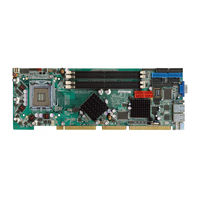
PICMG 1.0 CPU Card with LGA775 CPU Socket VGA, DVI, Gigabit Ethernet, SATA 2 and Audio RoHS Compliant
Brand:
IEI Technology
| Category:
Computer Hardware
| Size: 4 MB
Table of Contents
Table of Contents
4
1 Introduction
13
Benefits
14
Model Variations
14
Overview
14
Table 1-1: Model Variations
14
Figure 1-1: Overview
16
Technical Specifications
17
Features
15
Connectors
16
Overview Picture
16
Table 1-2: Technical Specifications
18
2 Detailed Specifications
19
Compatible Iei Backplanes
20
Cpu Support
20
Table 2-1: Supported Cpus
20
Data Flow
21
Figure 2-1: Data Flow Block Diagram
21
Table 2-2: Power Consumption
22
3 Connectors and Jumpers
23
Figure 3-1: Connector and Jumper Locations
24
Peripheral Interface Connectors
24
Layout
24
External Peripheral Interface Connectors
25
Table 3-2: External Peripheral Interface Connectors
25
Figure 3-2: ATX-12V Connector Location
26
Table 3-3: On-Board Jumper
26
Audio Module Connector
27
Backplane to Mainboard Power Connector
27
Jumpers
26
Table 3-1: Peripheral Interface Connectors
25
Internal Peripheral Connectors
26
ATX-12V Power Source Connector
26
Figure 3-3: Audio Module Connector Location
27
Figure 3-4: Backplane to Mainboard Power Connector Location
28
Figure 3-5: CPU Fan Connector Location
28
Figure 3-6: DIO Connector Location
29
Table 3-7: CPU Fan Connector Pinouts
29
Table 3-8: DIO Connector Pinouts
29
FDD Connector
30
Figure 3-7: DVI Connector Location
30
Table 3-9: DVI Connector Pinouts
30
Figure 3-8: FDD Connector Location
31
Front Panel Connector
31
Table 3-10: FDD Connector Pinouts
31
Figure 3-9: Front Panel Connector Location
32
IDE Connector
32
Table 3-4: ATX-12V Connector Pinouts
27
Table 3-5: Audio Module Connector Pinouts
27
Table 3-6: Backplane to Mainboard Power Pinouts
28
Digital Input/Output (DIO) Connector
29
DVI (Digital Visual Interface) Connector (Optional)
29
CPU Fan Connector
28
Table 3-11: Front Panel Connector Location
32
Figure 3-10: IDE Connector Location
33
Table 3-12: IDE Connector Pinouts
33
Table 3-13: Irda Interface Connector Pinouts
34
Figure 3-12: Keyboard Connector Location
35
Figure3-13: Memory Connectors Location
35
Memory Connectors
35
Parallel Port Connector
35
Table 3-14: KB1 Connector Pinouts
35
Figure 3-14: Parallel Port Connector Location
36
Serial Port Connectors
36
Table 3-15: Parallel Port Connector Pinouts
36
Figure 3-15: RS-232 Serial Port Connectors Location
37
SATA Drive Connectors
37
Table 3-16: RS-232 Serial Port Connectors Pinouts
37
Figure 3-16: SATA Connectors Location
38
Table 3-17: SATA Connectors Pinouts
38
External Peripheral Interface Connectors
39
Figure 3-17: USB Port Connector Location
39
Table 3-18: USB Port Connector Pinouts
39
Figure 3-18: External Peripheral Interface Connector Panel
40
Figure 3-19: RJ-45 Ethernet Connector
40
LAN Connectors
40
Table 3-19: LAN Pinouts
40
Figure 3-20: Mini-DIN 6 PS/2 Connector
41
Mini-DIN 6 PS/2 Connector
41
Table 3-20: RJ-45 Ethernet Connector Leds
41
USB Connector
42
VGA Connector
42
USB Connectors
39
Table 3-21: Mini-DIN 6 PS/2 Connector
42
Table 3-22: USB Port Pinouts
42
Figure 3-21: VGA Connector
43
Table 3-23: VGA Connector Pinouts
43
Figure 3-11: Irda Interface Connector Location
34
Irda Interface Connector
34
Keyboard Connector
34
4 Installation and Configuration
44
Anti-Static Precautions
45
Installation Considerations
45
Installation Notices
45
Unpacking
46
Unpacking Precautions
46
Checklist
47
Wsb-9454 Cpu Card Installation
47
CPU Installation
48
Figure 4-2: Remove the CPU Socket Protective Shield
49
Figure 4-4: Insert the Socket LGA775 CPU
51
Figure 4-6: Securing the Heat Sink to the PCB
53
Figure 4-7: Installing the DIMM Module
54
Peripheral Device Connection
54
IDE Drive Connector
55
Table 4-1: IEI Provided Cables
55
Figure 4-8: Connection of IDE Connector
56
Floppy Drive Connector
56
Figure 4-9: SATA Drive Cable Connection
57
SATA Drive Connection
57
Figure 4-10: SATA Drive Connection
58
Installing the RS-232 Cable
58
Figure 4-11: Dual RS-232 Cable Installation
59
USB 2.0 Cable Connection
59
Figure 4-12: USB Cable Installation
60
Clear CMOS Jumper
61
On-Board Jumper
61
Table 4-2: On-Board Jumpers
61
Figure4-13: Clear CMOS Jumper Location
62
SPI Flash Connector
62
Table 4-3: Clear CMOS Jumper Settings
62
Chassis Installation
63
Figure4-14: SPI Flash Connector Location
63
Keyboard and Mouse Connection
63
Rear Panel Connectors
63
VGA Port Installation
63
Ethernet Connection
64
USB Connection
64
Figure 4-5: Cooling Kit
52
DIMM Module Installation
53
Figure 4-1: Intel LGA775 Socket
49
Figure 4-3: Open the CPU Socket Load Plate
50
Cooling Kit Installation
51
5 Bios
65
Introduction
66
Starting Setup
66
Using Setup
66
Getting Help
67
Unable to Reboot after Configuration Changes
67
BIOS Menu Bar
67
Main
68
Advanced
69
CPU Configuration
70
IDE Configuration
71
IDE Master, IDE Slave
75
Floppy Configuration
80
Super IO Configuration
81
Hardware Health Configuration
84
Power Function
85
Remote Access Configuration
88
USB Configuration
92
USB Mass Storage Device Configuration
93
Pci/Pnp
95
Boot
98
Boot Settings Configuration
98
Boot Device Priority
100
Hard Disk Drives
101
Removable Drives
101
CD/DVD Drives
102
Security
103
Chipset
104
Northbridge Configuration
106
Southbridge Configuration
107
Exit
109
6 Software Drivers
111
Available Software Drivers
112
Chipset Driver Installation
112
Figure 6-1: Installshield Wizard Preparation Screen
113
Figure 6-2: Welcome Screen
113
Figure 6-3: License Agreement
114
Figure 6-4: Readme Information
114
Figure 6-5: Restart the Computer
115
Figure 6-12: Access Windows Control Panel
119
Figure 6-14: Double Click the Device Manager Tab
120
Figure 6-13: Double Click the System Icon
120
Figure 6-16: Search for Suitable Driver
121
Figure 6-15: Device Manager List
121
Figure 6-18: Location Browsing Window
122
Figure 6-17: Locate Driver Files
122
Realtek Ac'97 (Alc655) Audio Driver Installation
123
BIOS Setup
123
Driver Installation
123
Vga Driver
115
Figure 6-6: Starting Install Shield Wizard Screen
116
Figure 6-7: Preparing Setup Screen
116
Figure 6-8: VGA Driver Installation Welcome Screen
117
Figure 6-9: VGA Driver License Agreement
117
Figure 6-10: VGA Driver Installing Notice
118
Figure 6-11: VGA Driver Installation Complete
118
Realtek LAN Driver (for Gbe LAN) Installation
119
Figure 6-19: CD 4-AUDIO\AC-Kit08R\Windows Folder
124
Figure 6-20: AC`97 Audio Driver Install Shield Wizard Starting
124
Figure 6-21: AC`97 Audio Driver Setup Preparation
125
Figure 6-22: AC`97 Audio Driver Welcome Screen
125
Figure 6-23: AC`97 Audio Driver Software Configuration
126
Figure 6-24: AC`97 Audio Driver Digital Signal
126
Figure 6-25: AC`97 Audio Driver Installation Begins
127
Figure 6-26: AC`97 Audio Driver Installation Complete
127
ABIOS Options
129
B Terminology
133
C Digital I/O Interface
137
Introduction
138
Dio Connector Pinouts
138
Assembly Language Samples
139
Enable the DIO Input Function
139
Enable the DIO Output Function
139
D Watchdog Timer
140
E Hazardous Materials Disclosure
143
Hazardous Materials Disclosure Table for IPB Products Certified as Rohs Compliant under 2002/95/EC Without Mercury
144
Advertisement
Advertisement
Related Products
IEI Technology WSB-9454DVI-R40
IEI Technology WSB-9154
IEI Technology WSB-H610
IEI Technology WSB-H610-R11
IEI Technology WSB-H610-DVI-R11
IEI Technology WAFER-ULT4
IEI Technology WAFER-TGL-U-C-R10
IEI Technology WAFER-BT-E38 1W2 Series
IEI Technology WAFER-BT-E38151W2
IEI Technology WAFER-ADL-P-CC-R10
IEI Technology Categories
Motherboard
Touch Panel
Computer Hardware
Single board computers
Desktop
More IEI Technology Manuals
Login
Sign In
OR
Sign in with Facebook
Sign in with Google
Upload manual
Upload from disk
Upload from URL