Sign In
Upload
Manuals
Brands
IEI Technology Manuals
Industrial PC
TANK-870AI SERIES
IEI Technology TANK-870AI SERIES Manuals
Manuals and User Guides for IEI Technology TANK-870AI SERIES. We have
1
IEI Technology TANK-870AI SERIES manual available for free PDF download: User Manual
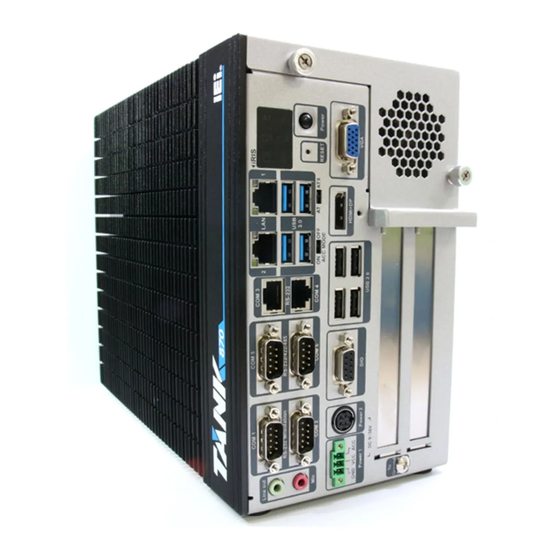
IEI Technology TANK-870AI SERIES User Manual (137 pages)
embedded system with 6th generation intel core processor 8GB DDR4 pre-installed memory VGA/HDMI/DP/IDP two gigabit ethernet RS-232/422/485 ROHS compliant
Brand:
IEI Technology
| Category:
Industrial PC
| Size: 2 MB
Table of Contents
Table of Contents
5
1 Introduction
15
Figure 1-1: TANK-870AI Series
16
Table 1-1: TANK-870AI Series Model Variations
17
Technical Specifications
18
Front Panel
20
Overview
16
Features
17
Model Variations
17
Table 1-2: Technical Specifications
20
Figure 1-2: TANK-870AI Series Front Panel
20
Figure 1-4: TANK-870AI Series LED Indicators
22
Table 1-3: LED Indicators Description
23
Backplane Options
24
Figure 1-3: TANK-870AI Series Rear Panel
21
Led Indicators
22
Rear Panel
21
Figure 1-5: HPE-2S86 (for 2A Model)
24
Table 1-4: Supported Signals
24
Table 1-5: Rated Voltage and Current
25
Physical Dimensions
26
Figure 1-6: TANK-870AI Slot Physical Dimensions (Millimeters)
26
2 Unpacking
27
Anti-Static Precautions
28
Unpacking Precautions
28
Unpacking Checklist
29
3 Installation
33
Hard Disk Drive (Hdd) Installation
34
Installation Precautions
34
Figure 3-2: Remove the Cover from TANK-870AI Series
35
Figure 3-1: Unscrew the Cover
35
Figure 3-3: HDD Installation
36
Figure 3-4: HDD Retention Screws
36
Figure 3-5: System Fan Installation
37
Figure 3-6: Wi-Fi Antenna Installation
38
External Peripheral Interface Connectors
39
Figure 3-7: Mounting Bracket Retention Screws
39
ACC Mode Selection
40
Figure 3-8: ACC Mode Switch
40
AT/ATX Power Mode Selection
41
Audio Connector
41
Figure 3-13: LAN Connection
43
Figure 3-14: RJ-45 Ethernet Connector
43
Figure 3-15: 3-Pin Terminal Block
44
Figure 3-16: Power Input Connector
44
Figure 3-17: RJ-45 RS-232 Serial Device Connection
45
Figure 3-18: RJ-45 RS-232 Serial Port Connector
45
RS-232/422/485 Serial Port Connectors
45
Figure 3-19: Serial Device Connector
46
Figure 3-20: DB-9 RS-232/422/485 Serial Port Connector
46
USB Connectors
46
Figure 3-21: USB Device Connection
47
VGA Connector
47
Figure 3-22: VGA Connector
48
Figure 3-23: VGA Connector
48
Internal Peripheral Interface Connectors
48
TPM Module Installation
48
Figure 3-25: TPM Module Installation
49
Idp Module Installation
50
Mounting the System with Mounting Brackets
38
Wi-Fi Antenna Installation
38
Figure 3-10: Audio Connector
41
Figure 3-9: AT/ATX Power Mode Switch
41
Digital Input/Output Connector
42
Figure 3-11: DIO Connector
42
Figure 3-12: HDMI/DP Connection
42
HDMI/DP Connector
42
LAN Connectors
42
Table 3-1: RJ-45 Ethernet Connector Leds
43
Power Input, 3-Pin Terminal Block
44
Power Input, 4-Pin DIN Connector
44
RS-232 Serial Ports
44
System Fan Installation
37
Figure 3-24: TPM Connector Location
49
Table 3-2: TPM Connector Pinouts
50
Figure 3-26: Internal Displayport Connector Location
51
Figure 3-28: Idp Module Installation
52
Figure 3-29: Remove Expansion Slot Bracket
52
Table 3-3: Idp Converter Cards
53
Power
54
Powering On/Off the System
54
Table 3-4: Power LED Indicators Description
55
Figure 3-31: Power Connectors
55
ACC off Mode
56
Figure 3-27: Idp Module with Bracket
51
Figure 3-30: Power Button
54
ACC on Mode
55
4 System Motherboard
57
Figure 4-1: System Motherboard (Front)
58
Table 4-2: Backplane Power Connector Pinouts (JP1)
59
Table 4-1: Peripheral Interface Connectors
59
Battery Connector (BAT1)
60
BIOS Programming Connector (JSPI1)
60
CPU Fan Connector (CPU_FAN1)
60
Displayport Connector (DP1)
60
Figure 4-2: System Motherboard (Rear)
58
Overview
58
Layout
58
Internal Peripheral Connectors
59
Backplane Power Connector (JP1)
59
Table 4-5: CPU Fan Connector Pinouts (CPU_FAN1)
60
Table 4-4: BIOS Programming Connector Pinouts (JSPI1)
60
Table 4-3: Battery Connector Pinouts (BAT1)
60
EC Debug Connector (CN4)
61
EC Programming Connector (JSPI2)
61
Keyboard and Mouse Connector (KB_MS1)
61
Table 4-7: EC Debug Connector Pinouts (CN4)
61
Table 4-6: Displayport Connector Pinouts (DP1)
61
Table 4-8: EC Programming Connector Pinouts (JSPI2)
61
Table 4-10: LED Connector Pinouts (J2)
62
Table 4-11: SATA Power Connectors Pinouts (CN2, CN3)
62
Table 4-12: TPM Connector Pinouts (TPM1)
62
Table 4-13: USB 3.0 Connectors Pinouts (USB3-1)
63
Table 4-14: Rear Panel Connectors
63
USB 3.0 Connectors (USB3-1)
63
Audio Jack (JAUDIO1)
64
DIO Connector (DIO1)
64
Ethernet and USB 2.0 Connectors (LAN1_USB1)
64
Table 4-15: Audio Jack Pinouts (JAUDIO1)
64
Table 4-16: DIO Connector Pinouts (DIO1)
64
Table 4-17: USB 2.0 Port Pinouts (USB1)
64
Ethernet and USB 2.0 Connectors (LAN2_USB2)
65
Power Connector (PWR1)
65
Table 4-18: LAN Pinouts (LAN1)
65
Table 4-19: USB 2.0 Port Pinouts (USB2)
65
Table 4-20: LAN Pinouts (LAN2)
65
Table 4-21: Power Connector Pinouts (PWR2)
65
Power Connector (PWR2)
66
RS-232/422/485 Serial Port Connector (COM5_6)
66
Serial Port Connector (COM1_2)
66
Serial Port Connectors (COM3_4)
66
Table 4-22: Power Connector Pinouts (PWR1)
66
Table 4-23: RS-232 Serial Port Connector Pinouts (COM1_2)
66
Table 4-24: RS-232 Serial Port Connectors Pinouts (COM3_4)
66
Table 4-25: RS-232/422/485 Serial Port Connector Pinout (COM5_6)
67
Table 4-26: USB 3.0 Connectors Pinouts (USB3_CN1)
67
Table 4-27: USB 3.0 Connectors Pinouts (USB3_CN2)
67
USB 3.0 Connectors (USB3_CN1)
67
USB 3.0 Connectors (USB3_CN2)
67
Table 4-28: VGA Connector Pinouts (VGA1)
68
VGA Connector (VGA1)
68
Table 4-9: Keyboard and Mouse Connector Pinouts (KB_MS1)
61
TPM Connector (TPM1)
62
External Interface Panel Connectors
63
LED Connector (J2)
62
SATA Power Connectors (CN2, CN3)
62
5 Bios
69
Introduction
70
Starting Setup
70
Using Setup
70
Getting Help
71
Unable to Reboot after Configuration Changes
71
BIOS Menu Bar
71
Table 5-1: BIOS Navigation Keys
71
Main
73
Advanced
74
BIOS Menu 1: Main
74
CPU Configuration
75
BIOS Menu 2: Advanced
75
BIOS Menu 3: CPU Configuration
76
Trusted Computing
78
BIOS Menu 4: Trusted Computing
78
ACPI Settings
79
BIOS Menu 5: ACPI Configuration
79
SATA Configuration
80
BIOS Menu 6: SATA Configuration
80
AMT Configuration
81
BIOS Menu 7: AMT Configuration
81
F81866 Super IO Configuration
82
BIOS Menu 8: F81866 Super IO Configuration
82
Serial Port N Configuration
83
Serial Port 1 Configuration
83
BIOS Menu 9: Serial Port N Configuration Menu
83
Serial Port 2 Configuration
84
Serial Port 3 Configuration
85
Serial Port 4 Configuration
86
Serial Port 5 Configuration
86
Serial Port 6 Configuration
87
RTC Wake Settings
88
BIOS Menu 10: RTC Wake Settings
89
Serial Port Console Redirection
90
BIOS Menu 11: Serial Port Console Redirection
90
Console Redirection Settings
91
BIOS Menu 12: Console Redirection Settings
91
Intel TXT(LT) Configuration
93
BIOS Menu 13: Intel TXT(LT) Configuration
93
USB Configuration
94
BIOS Menu 14: USB Configuration
94
Iei Feature
95
BIOS Menu 15: Iei Feature
95
Iwdd H/W Monitor
96
BIOS Menu 16: F81866 H/W Monitor
96
Smart Fan Mode Configuration
97
BIOS Menu 17: Smart Fan Mode Configuration
97
Chipset
98
System Agent (SA) Configuration
99
BIOS Menu 18: Chipset
99
BIOS Menu 19: System Agent (SA) Configuration
99
Memory Configuration
100
BIOS Menu 20: Memory Configuration
100
Graphics Configuration
101
BIOS Menu 21: Graphics Configuration
101
PEG Port Configuration
103
BIOS Menu 22: NB Pcie Configuration
103
PCH-IO Configuration
104
BIOS Menu 23: PCH-IO Configuration
104
PCI Express Configuration
105
BIOS Menu 24: PCI Express Configuration
105
HD Audio Configuration
106
BIOS Menu 25: HD Audio Configuration
106
Security
107
BIOS Menu 26: Security
107
Boot
108
BIOS Menu 27: Boot
108
Save & Exit
110
BIOS Menu 28:Exit
110
Server Mgmt
111
BIOS Menu 29: Server Mgmt
111
System Event Log
112
BIOS Menu 30: System Event Log
112
BMC Network Configuration
113
A Regulatory Compliance
114
BBIOS Options
119
C Terminology
123
D Safety Precautions
127
Safety Precautions
128
D.1 S Afety P Recautions
128
Maintenance and Cleaning Precautions
130
D.2 M Aintenance and C Leaning P Recautions
130
E Digital I/O Interface
132
Introduction
133
E.1 I Ntroduction
133
Assembly Language Sample 1
134
Assembly Language Sample 2
134
E.2 a Ssembly L Anguage S Ample 1
134
F Hazardous Materials Disclosure
135
Advertisement
Advertisement
Related Products
IEI Technology TANK-870-Q170i-i5/4G/2A-R10
IEI Technology TANK-870-Q170i-i7/4G/2A-R10
IEI Technology TANK-870-Q170i-i7/4G/4A-R10
IEI Technology TANK-870-Q170i-i7/4G/4B-R10
IEI Technology TANK-870-Q170i-i5/4G/2B
IEI Technology TANK-870-Q170i-i5/4G/4A
IEI Technology TANK-870e-H110 Series
IEI Technology TANK-870e-H110-i5/4G/3B
IEI Technology TANK-870-Q170 Series
IEI Technology TANK-870-Q170i-i5/4G/2B-R10
IEI Technology Categories
Motherboard
Touch Panel
Computer Hardware
Single board computers
Desktop
More IEI Technology Manuals
Login
Sign In
OR
Sign in with Facebook
Sign in with Google
Upload manual
Upload from disk
Upload from URL