Sign In
Upload
Manuals
Brands
IEI Technology Manuals
Computer Hardware
TANK-700
IEI Technology TANK-700 Manuals
Manuals and User Guides for IEI Technology TANK-700. We have
1
IEI Technology TANK-700 manual available for free PDF download: User Manual
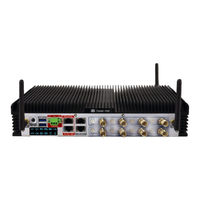
IEI Technology TANK-700 User Manual (145 pages)
High Performance Fanless Embedded System with Intel 32nm CPU, On-board 2.0 GB DDR3 Memory, VGA/HDMI, USB 3.0, Dual Combo (SFP Fiber/RJ-45) Gigabit LAN, Isolated CAN-bus, Audio, 9V-36V DC Input, RoHS Compliant
Brand:
IEI Technology
| Category:
Computer Hardware
| Size: 6 MB
Table of Contents
Table of Contents
5
Introduction
13
Overview
14
Model Variations
14
Figure 1-1: TANK-700
14
Table 1-1: TANK-700 Model Variations
14
Features
15
Technical Specifications
15
Connector Panel
17
Front Panel
17
Table 1-2: Technical Specifications
17
Rear Panel
18
Figure 1-2: TANK-700 Front Panel
18
Figure 1-3: TANK-700 Rear Panel
19
Led Indicators
20
Figure 1-4: TANK-700 LED Indicators
20
Dimensions
21
Figure 1-5: Physical Dimensions (Millimeters)
21
Unpacking
22
Anti-Static Precautions
23
Unpacking Precautions
23
Unpacking Checklist
24
Installation
27
Installation Precautions
28
Hard Disk Drive (Hdd) Installation
28
Figure 3-1: Bottom Panel Retention Screws
29
Figure 3-2: HDD Bracket Retention Screws
29
Pluggable CAN-Bus Terminal Block Installation
30
Figure 3-3: HDD Installation
30
Figure 3-4: HDD Bracket Installation
30
Pluggable DC-In Terminal Block Installation
31
Figure 3-5: Pluggable CAN-Bus Terminal Block Installation
31
Pluggable Remote Control Terminal Block Installation
32
Figure 3-6: Pluggable DC-In Terminal Block Installation
32
Sfp Module Installation
33
Figure 3-7: Pluggable Remote Control Terminal Block Installation
33
Figure 3-8: SFP Module Installation
33
So-DIMM Installation
34
Figure 3-9: Retention Screws
34
Figure 3-10: SO-DIMM Socket
35
Figure 3-11: SO-DIMM Installation
35
Mounting the System with Mounting Brackets
36
Figure 3-12: Mounting Bracket Retention Screws
36
External Peripheral Interface Connectors
37
ACC Mode Selection
38
AT/ATX Power Mode Selection
38
Figure 3-13: ACC Mode Switch
38
Figure 3-14: AT/ATX Power Mode Switch
38
Audio Connector
39
Audio/Video Input Connectors
39
CAN-Bus Terminal Block
39
Figure 3-15: Audio Connector
39
Figure 3-16: CAN-Bus Terminal Block Pinouts
39
Digital Input/Output Connector
40
HDMI Connector
40
Figure 3-17: DIO Connector Pinout Location
40
Table 3-1: DIO Connector Pinouts
40
LAN Connectors
41
Table 3-2: HDMI Connector Pinouts
41
Figure 3-18: LAN Connection
42
Figure 3-19: RJ-45 Ethernet Connector
42
Table 3-3: LAN Pinouts
42
Power Input, 4-Pin Terminal Block
43
Power Input, 4-Pin DIN Connector
43
Figure 3-20: 4-Pin Terminal Block Pinout Location
43
Table 3-4: RJ-45 Ethernet Connector Leds
43
Table 3-5: 4-Pin Terminal Block Pinouts
43
Remote Control Connector
44
Figure 3-21: Power Input Connector
44
Figure 3-22: Remote Control Terminal Block Pinout Location
44
Table 3-6: Power Input Pinouts
44
RS-232 Serial Ports
45
Figure 3-23: RJ-45 RS-232 Serial Device Connection
45
Figure 3-24: RJ-45 RS-232 Serial Port Pinout Location
46
Figure 3-25: DB-9 Connector Pinout Location
46
Table 3-7: RJ-45 RS-232 Serial Port Pinouts
46
Table 3-8: DB-9 Connector Pinouts
46
RS-422/485 Serial Ports
47
Figure 3-26: RJ-45 RS-422/485 Serial Device Connection
47
Figure 3-27: RJ-45 RS-422/485 Serial Port Pinout Location
48
Figure 3-28: DB-9 Connector Pinout Location
48
Table 3-9: RJ-45 RS-422/485 Serial Port Pinouts
48
Table 3-10: DB-9 Connector Pinouts
48
Serial Port Connectors
49
Figure 3-29: Serial Device Connector
49
SFP Fiber Connectors
50
USB Connectors
50
Figure 3-30: Serial Port Pinout Location
50
Table 3-11: Serial Port Pinouts
50
VGA Connector
51
Figure 3-31: USB Device Connection
51
Table 3-12: USB Port Pinouts
51
Figure 3-32: VGA Connector
52
Figure 3-33: VGA Connector
52
Powering On/Off the System
53
Figure 3-34: Power Button
53
Table 3-13: VGA Connector Pinouts
53
Redundant Power
54
Figure 3-35: Power Connectors
54
Acc on
55
Boot-Up
55
Figure 3-36: ACC On: at Mode
55
Figure 3-37: ACC On: ATX Mode
55
Switch to Backup Power
56
Shutdown
56
Figure 3-38: ACC On: Switch between PWR1 and PWR2
56
Figure 3-39: ACC On: Shutdown
56
Acc off
57
Boot-Up
57
Figure 3-40: ACC Off: at Mode
57
Figure 3-41: ACC Off: ATX Mode
57
Switch to Backup Power
58
Figure 3-42: ACC Off: Switch between PWR1 and PWR2
58
Shutdown
59
Figure 3-43: ACC Off: Shutdown
59
Bios
60
Introduction
61
Starting Setup
61
Using Setup
61
Getting Help
62
Unable to Reboot after Configuration Changes
62
BIOS Menu Bar
62
Table 4-1: BIOS Navigation Keys
62
Main
63
Advanced
64
ACPI Settings
65
Trusted Computing
66
CPU Configuration
67
SATA Configuration
68
USB Configuration
69
Second Super IO Configuration
71
Serial Port N Configuration
71
Super IO Configuration
74
Serial Port N Configuration
75
H/W Monitor
81
Serial Port Console Redirection
82
Iei Feature
84
Chipset
85
Northbridge Configuration
86
Graphics Configuration
86
Southbridge Configuration
88
ME Configuration
91
Boot
92
Security
93
Exit
94
A One Key Recovery
96
One Key Recovery Introduction
97
Figure A-1: IEI One Key Recovery Tool Menu
97
System Requirement
98
Supported Operating System
99
Setup Procedure for Windows
100
Hardware and BIOS Setup
101
Create Partitions
101
Figure A-2: Launching the Recovery Tool
102
Figure A-3: Recovery Tool Setup Menu
102
Figure A-4: Command Mode
103
Figure A-5: Partition Creation Commands
104
Install Operating System, Drivers and Applications
105
Build-Up Recovery Partition
106
Figure A-6: Launching the Recovery Tool
106
Figure A-7: System Configuration for Windows
106
Figure A-8: Building the Recovery Partition
107
Figure A-9: Press any Key to Continue
107
Create Factory Default Image
108
Figure A-10: Press F3 to Boot into Recovery Mode
108
Figure A-11: Recovery Tool Menu
108
Figure A-12: about Symantec Ghost Window
109
Figure A-13: Symantec Ghost Path
109
Figure A-14: Select a Local Source Drive
110
Figure A-15: Select a Source Partition from Basic Drive
110
Figure A-16: File Name to Copy Image to
111
Figure A-17: Compress Image
111
Figure A-18: Image Creation Confirmation
112
Figure A-19: Image Creation Process
112
Figure A-20: Image Creation Complete
112
Auto Recovery Setup Procedure
113
Figure A-21: Press any Key to Continue
113
Figure A-22: Auto Recovery Utility
114
Figure A-23: Launching the Recovery Tool
114
Figure A-24: Auto Recovery Environment for Windows
114
Figure A-25: Building the Auto Recovery Partition
115
Figure A-26: Factory Default Image Confirmation
115
Figure A-27: Image Creation Complete
116
Figure A-28: Press any Key to Continue
116
Setup Procedure for Linux
117
Figure A-29: Partitions for Linux
118
Figure A-30: Manual Recovery Environment for Linux
119
Figure A-31: Access Menu.lst in Linux (Text Mode)
120
Figure A-32: Recovery Tool Menu
120
Recovery Tool Functions
121
Figure A-33: Recovery Tool Main Menu
121
Factory Restore
122
Figure A-34: Restore Factory Default
122
Backup System
123
Figure A-35: Recovery Complete Window
123
Figure A-36: Backup System
123
Restore Your Last Backup
124
Figure A-37: System Backup Complete Window
124
Figure A-38: Restore Backup
124
Manual
125
Figure A-39: Restore System Backup Complete Window
125
Figure A-40: Symantec Ghost Window
125
Restore Systems from a Linux Server through Lan
126
Configure DHCP Server Settings
127
Configure TFTP Settings
128
Configure One Key Recovery Server Settings
129
Start the DHCP, TFTP and HTTP
130
Create Shared Directory
130
Setup a Client System for Auto Recovery
131
Other Information
134
Using AHCI Mode or Ali M5283 / VIA VT6421A Controller
134
System Memory Requirement
136
B Safety Precautions
137
Safety Precautions
138
General Safety Precautions
138
Anti-Static Precautions
139
Product Disposal
140
Maintenance and Cleaning Precautions
140
Maintenance and Cleaning
140
Cleaning Tools
141
C Hazardous Materials Disclosure
142
Hazardous Materials Disclosure Table for IPB Products Certified as Rohs Compliant under 2002/95/EC Without Mercury
143
Advertisement
Advertisement
Related Products
IEI Technology TANK-101BW
IEI Technology TANK-101B
IEI Technology TANK-600 Series
IEI Technology TANK-600-CV-D2550
IEI Technology TANK-600-CV-N2600
IEI Technology TANGO-7010 Series
IEI Technology TANGO-7010-i9AWC-R10
IEI Technology TANGO-7010-i7AWC-R10
IEI Technology TANGO-7010-i5AWC-R10
IEI Technology TANGO-7010-i3AWC-R10
IEI Technology Categories
Motherboard
Touch Panel
Computer Hardware
Single board computers
Desktop
More IEI Technology Manuals
Login
Sign In
OR
Sign in with Facebook
Sign in with Google
Upload manual
Upload from disk
Upload from URL