Sign In
Upload
Manuals
Brands
IEI Technology Manuals
Computer Hardware
TANK-101BW
IEI Technology TANK-101BW Manuals
Manuals and User Guides for IEI Technology TANK-101BW. We have
1
IEI Technology TANK-101BW manual available for free PDF download: User Manual
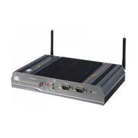
IEI Technology TANK-101BW User Manual (116 pages)
Fanless Embedded System with Intel Atom D525/N-455 CPU, On-board 1.0 GB DDR3 Memory, Two Isolated CAN-bus Ports, One Isolated Serial Port, RoHS Compliant
Brand:
IEI Technology
| Category:
Computer Hardware
| Size: 5 MB
Table of Contents
Table of Contents
4
1 Introduction
10
Figure 1-1: TANK-101B/BW
11
Figure 1-2: TANK-101B/BW Front Panel
14
Figure 1-3: TANK-101B/BW Rear Panel
15
Rear Panel
15
Dimensions
16
Model Variations
11
Overview
11
Table 1-1: TANK-101B/BW Model Variations
11
Table 1-2: Technical Specifications
13
Connector Panel
14
Front Panel
14
Features
12
Technical Specifications
12
Figure 1-4: Physical Dimensions (Millimeters)
16
2 Unpacking
17
Anti-Static Precautions
18
Unpacking Precautions
18
Unpacking Checklist
19
3 Installation
21
Cf Card Installation
22
Installation Precautions
22
Figure 3-2: CF Card Installation
23
Figure 3-3: Bottom Panel Retention Screws
24
Figure 3-5: Retention Screw Holes
25
Figure 3-6: Wall-Mounting Bracket
26
Figure 3-7: Mount the Embedded System
27
Table 3-1: Clear CMOS Jumper Settings
28
Audio Connector
29
External Peripheral Interface Connectors
29
Figure 3-8: Audio Connector
29
CAN-Bus Connectors
30
Compactflash® Card Slot
30
LAN Connectors
30
Figure 3-1: CF Card Slot
23
Figure 3-4: HDD Installation
24
Mounting the System with Wall Mount Kit
26
Jumper Settings
28
Clear CMOS Jumper
28
Figure 3-9: CAN-Bus Connector Pinout Location
30
Table 3-2: CAN-Bus Connector Pinouts
30
Figure 3-10: LAN Connection
31
Figure 3-11: RJ-45 Ethernet Connector
32
Figure 3-12: 3-Pin Terminal Block Pinout Location
32
Table 3-4: RJ-45 Ethernet Connector Leds
32
Figure 3-13: Serial Device Connector
33
Serial Port Connectors
33
Figure 3-14: RS-232 Serial Port Pinout Location
34
RS-422/485 Serial Port Connector
34
Table 3-5: RS-232 Serial Port Pinouts
34
Table 3-6: RS-422/485 Serial Port Pinouts
35
USB Connectors
35
VGA Connector
36
Table 3-3: LAN Pinouts
31
3-Pin Power Terminal Block
32
Hard Disk Drive (Hdd) Installation
23
Mounting the System with Mounting Brackets
25
Figure 3-15: RS-422/485 Serial Port Pinout Location
35
Table 3-7: USB Port Pinouts
36
Figure 3-16: USB Device Connection
36
Figure 3-17: VGA Connector
37
Figure 3-18: VGA Connector
37
Table 3-8: VGA Connector Pinouts
38
4 Bios
39
Introduction
40
Starting Setup
40
Using Setup
40
Getting Help
41
Unable to Reboot after Configuration Changes
41
BIOS Menu Bar
41
Table 4-1: BIOS Navigation Keys
41
Main
42
Advanced
43
ACPI Settings
44
Trusted Computing
45
CPU Configuration
45
IDE Configuration
46
USB Configuration
48
Super IO Configuration
49
Serial Port N Configuration
50
H/W Monitor
54
Serial Port Console Redirection
55
Chipset
57
Host Bridge Configuration
58
Onchip VGA Configuration
59
South Bridge Configuration
59
Intel IGD SWSCI Opregion
61
Boot
62
Security
63
Exit
65
A One Key Recovery
67
A.1 O Ne K Ey R Ecovery I Ntroduction
68
Figure A-1: IEI One Key Recovery Tool Menu
68
One Key Recovery Introduction
68
System Requirement
69
Supported Operating System
70
Setup Procedure for Windows
71
Create Partitions
72
Hardware and BIOS Setup
72
Figure A-3: Recovery Tool Setup Menu
73
Figure A-6: Launching the Recovery Tool
77
Figure A-7: System Configuration for Windows
77
Figure A-9: Press any Key to Continue
78
Create Factory Default Image
79
Figure A-2: Launching the Recovery Tool
73
Figure A-4: Command Mode
74
Figure A-5: Partition Creation Commands
75
Install Operating System, Drivers and Applications
76
Build-Up Recovery Partition
77
Figure A-8: Building the Recovery Partition
78
Figure A-10: Press F3 to Boot into Recovery Mode
79
Figure A-12: about Symantec Ghost Window
80
Figure A-13: Symantec Ghost Path
80
Figure A-21: Press any Key to Continue
84
Figure A-22: Auto Recovery Utility
85
Figure A-23: Launching the Recovery Tool
85
Figure A-24: Auto Recovery Environment for Windows
85
Figure A-25: Building the Auto Recovery Partition
86
Figure A-26: Factory Default Image Confirmation
86
Figure A-29: Partitions for Linux
89
Figure A-30: Manual Recovery Environment for Linux
90
Figure A-31: Access Menu.lst in Linux (Text Mode)
91
Figure A-32: Recovery Tool Menu
91
A.5 R Ecovery T Ool F Unctions
92
Figure A-33: Recovery Tool Main Menu
92
Recovery Tool Functions
92
Factory Restore
93
Figure A-34: Restore Factory Default
93
Backup System
94
Figure A-35: Recovery Complete Window
94
Figure A-36: Backup System
94
Figure A-37: System Backup Complete Window
95
Figure A-38: Restore Backup
95
Restore Your Last Backup
95
Figure A-39: Restore System Backup Complete Window
96
Figure A-40: Symantec Ghost Window
96
Manual
96
Restore Systems from a Linux Server through Lan
97
Configure DHCP Server Settings
98
Configure TFTP Settings
99
Configure One Key Recovery Server Settings
100
Create Shared Directory
101
Start the DHCP, TFTP and HTTP
101
Setup a Client System for Auto Recovery
102
A.7 O Ther I Nformation
105
Other Information
105
Using AHCI Mode or Ali M5283 / VIA VT6421A Controller
105
System Memory Requirement
107
Figure A-28: Press any Key to Continue
87
Figure A-27: Image Creation Complete
87
Setup Procedure for Linux
88
Figure A-11: Recovery Tool Menu
79
Figure A-14: Select a Local Source Drive
81
Figure A-15: Select a Source Partition from Basic Drive
81
Figure A-16: File Name to Copy Image to
82
Figure A-17: Compress Image
82
Figure A-20: Image Creation Complete
83
Figure A-19: Image Creation Process
83
Figure A-18: Image Creation Confirmation
83
Auto Recovery Setup Procedure
84
B Safety Precautions
108
Safety Precautions
109
General Safety Precautions
109
Anti-Static Precautions
110
Product Disposal
111
Maintenance and Cleaning Precautions
111
Maintenance and Cleaning
111
Cleaning Tools
112
C Hazardous Materials Disclosure
113
Hazardous Materials Disclosure Table for IPB Products Certified as Rohs Compliant under 2002/95/EC Without Mercury
114
C.1 H Azardous M Aterials D Isclosure T Able for Ipb P Roducts C Ertified as R O Hs C Ompliant U Nder 2002/95/Ec W Ithout M Ercury
114
Advertisement
Advertisement
Related Products
IEI Technology TANK-101B
IEI Technology TANK-700
IEI Technology TANK-600 Series
IEI Technology TANK-600-CV-D2550
IEI Technology TANK-600-CV-N2600
IEI Technology TANGO-7010 Series
IEI Technology TANGO-7010-i9AWC-R10
IEI Technology TANGO-7010-i7AWC-R10
IEI Technology TANGO-7010-i5AWC-R10
IEI Technology TANGO-7010-i3AWC-R10
IEI Technology Categories
Motherboard
Touch Panel
Computer Hardware
Single board computers
Desktop
More IEI Technology Manuals
Login
Sign In
OR
Sign in with Facebook
Sign in with Google
Upload manual
Upload from disk
Upload from URL