Sign In
Upload
Manuals
Brands
IEI Technology Manuals
Touch Panel
POC-W24C-ULT3
User Manuals: IEI Technology POC-W24C-ULT3 Panel PC
Manuals and User Guides for IEI Technology POC-W24C-ULT3 Panel PC. We have
2
IEI Technology POC-W24C-ULT3 Panel PC manuals available for free PDF download: User Manual, Quick Installation Manual
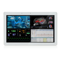
IEI Technology POC-W24C-ULT3 User Manual (160 pages)
24" FHD Medical Panel PC with Intel Core i7-6600U/Core i5-6300U/ Celeron 3855U CPU, 4 GB DDR RAM, Wi-Fi 802.11a/b/g/n/ac, PCAP Touchscreen, 5-Megapixel Camera, Microphone and RoHS
Brand:
IEI Technology
| Category:
Touch Panel
| Size: 6 MB
Table of Contents
Table of Contents
5
1 Introduction
16
Overview
17
Figure 1-1: POC-W24C-ULT3 FHD Medical Panel PC
17
Model Variations
18
Features
18
Table 1-1: Model Variations
18
Front Panel
19
Figure 1-2: Front View
19
Backlit Touch Buttons
20
Figure 1-3: Backlit Touch Buttons
20
Table 1-2: Touch Button Functions
20
Left Panel
21
Figure 1-4: Left View
21
Bottom Panel
22
Figure 1-5: Bottom Panel
22
Rear Panel
23
System Specifications
23
Figure 1-6: Rear View
23
Table 1-3: System Specifications
26
Dimensions
27
Figure 1-7: Dimensions (MM)
27
2 Unpacking
28
Unpacking
29
Packing List
30
Optional Items
31
3 Installation
34
Anti-Static Precautions
35
Installation Precautions
35
Installation and Configuration Steps
36
Hdd Installation
36
Figure 3-1: Back Cover Retention Screws
36
Figure 3-2: HDD Bracket Retention Screws
37
Handset Installation (Optional)
38
Figure 3-3: HDD Installation
38
Figure 3-4: Handset Holder Retention Screws
39
Figure 3-5: Handset Installation
39
Figure 3-6: Handset Driver Folder
40
Using Voip Handset
40
Figure 3-7: Handset Driver Installation
41
Figure 3-8: Allow API Access
41
Figure 3-9: Manage Program Access to Skype
42
Table 3-1: Handset Button Functions
43
Handle Installation (Optional)
44
Barcode Reader Installation
44
Figure 3-10: Handle Installation
44
H ANDLE I NSTALLATION 3.6.1 Barcode Reader Installation
44
Figure 3-11: Insert Barcode Reader Set
45
Figure 3-12: Install and Connect Barcode Reader Set
45
Figure 3-13: Barcode Reader Button
46
Figure 3-14: Reading Light
46
Reading Light
46
3-In-1 Combo Reader Installation (Optional)
47
Figure 3-15: 3-In-1 Combo Reader
47
Figure 3-16: USB Ports on the Left Panel
47
Using RFID Reader (Optional)
48
Figure 3-17: Combo Reader Installation
48
Eader (O Ptional )
48
Figure 3-18: RFID Program Location
49
Figure 3-19: IRFR-100 Icon
49
Figure 3-20: IRFR Screen
49
Figure 3-21: IRFR - Find Tags
50
Figure 3-22: IRFR - Uids
50
Rs-232/422/485 Serial Port Connection
51
Table 3-2: RS-232/422/485 Serial Port Pinouts
51
At/Atx Mode Selection
52
AT Power Mode
52
ATX Power Mode
52
Mounting the System
52
Figure 3-23: AT/ATX Switch Location
52
Figure 3-24: Wall-Mounting Bracket
53
Wall Mounting
53
Figure 3-25: Chassis Support Screws
55
Figure 3-26: Secure the Panel PC
55
Arm Mounting
56
Figure 3-27: VESA 75 and VESA 100 Mounting Retention Screw Holes
57
Figure 3-28: Arm Mounting
57
Stand Mounting
58
Powering on the System
58
Reset the System
59
Figure 3-29: Power Input Connector
59
Figure 3-30: Reset Button Location
59
4 Bios Setup
60
Introduction
61
Starting Setup
61
Using Setup
61
BIOS Menu Bar
62
Getting Help
62
Table 4-1: BIOS Navigation Keys
62
Main
63
BIOS Menu 1: Main
63
System Date [XX/XX
63
Advanced
64
BIOS Menu 2: Advanced
64
System Time [XX:XX:XX]
64
Trusted Computing
65
BIOS Menu 3: Trusted Computing
65
Security Device Support [Enable]
65
ACPI Settings
66
BIOS Menu 4: ACPI Settings
66
ACPI Sleep State [S3 (Suspend to RAM)]
66
F81866 Super IO Configuration
67
Serial Port N Configuration
67
BIOS Menu 5: F81866 Super IO Configuration
67
BIOS Menu 6: Serial Port N Configuration Menu
67
Change Settings [Auto]
67
Serial Port [Enabled]
67
Change Settings [Auto]
68
Device Mode [RS232]
68
Serial Port 1 Configuration
68
Serial Port [Enabled]
68
Serial Port 2 Configuration
69
F81866 H/W Monitor
70
BIOS Menu 7: F81866 H/W Monitor
70
PC Health Status
70
RTC Wake Settings
71
BIOS Menu 8: RTC Wake Settings
71
Wake System with Fixed Time [Disabled]
71
Serial Port Console Redirection
72
BIOS Menu 9: Serial Port Console Redirection
72
Console Redirection [Disabled]
72
Console Redirection Settings
73
BIOS Menu 10: Console Redirection Settings
73
Bits Per Second
73
Terminal Type [ANSI]
73
Data Bits [8]
74
Parity [None]
74
Legacy Console Redirection Settings
75
BIOS Menu 11: Legacy Console Redirection Settings
75
Legacy Serial Redirection Port [COM1]
75
Stop Bits
75
CPU Configuration
76
BIOS Menu 12: CPU Configuration
76
Active Processor Cores [All]
77
Hyper-Threading [Enabled]
77
Intel Virtualization Technology [Disabled]
77
SATA Configuration
78
BIOS Menu 13: SATA Configuration
78
CPU C State [Disabled]
78
Intel ® Speedstep(Tm) [Enabled]
78
Hot Plug [Disabled]
79
SATA Controller(S) [Enabled]
79
SATA Mode Selection [AHCI]
79
USB Configuration
80
BIOS Menu 14: USB Configuration
80
Legacy USB Support [Enabled]
80
USB Devices
80
IEI Feature
81
BIOS Menu 15: IEI Feature
81
Auto Recovery Function [Disabled]
81
Chipset
82
System Agent (SA) Configuration
82
BIOS Menu 16: Chipset
82
BIOS Menu 17: System Agent (SA) Configuration
82
VT-D [Disabled]
82
Graphics Configuration
83
BIOS Menu 18: Graphics Configuration
83
Primary Display [Auto]
83
DVMT Pre-Allocated [256M]
84
DVMT Total Gfx Mem [MAX]
84
Internal Graphics [Enabled]
84
LCD Control
85
BIOS Menu 19: LCD Control
85
Primary IGFX Boot Display [VBIOS Default]
85
Memory Configuration
86
PCH-IO Configuration
86
BIOS Menu 20: Memory Configuration
86
BIOS Menu 21: PCH-IO Configuration
86
PCI Express Configuration
87
BIOS Menu 22: PCI Express Configuration
87
Detect Non-Compliance Device [Disabled]
87
Pcie Speed [Auto]
87
HD Audio Configuration
88
BIOS Menu 23: HD Audio Configuration
88
HD Audio [Enabled]
88
Security
89
BIOS Menu 24: Security
89
Administrator Password
89
User Password
89
Boot
90
BIOS Menu 25: Boot
90
Bootup Numlock State [On]
90
Launch PXE Oprom [Disabled]
91
Option ROM Messages [Force BIOS]
91
Quiet Boot [Enabled]
91
UEFI Boot [Disabled]
91
Save & Exit
92
BIOS Menu 26: Save & Exit
92
Discard Changes and Reset
92
Restore Defaults
92
Restore User Defaults
92
Save as User Defaults
92
Save Changes and Reset
92
5 Driver Installation
94
Available Software Drivers
95
Figure 5-1: Available Drivers
95
Intel® Chipset Driver
96
Figure 5-2: Intel® Chipset Device Software Installation Wizard
96
Intel® Graphics Driver
97
Figure 5-3: Intel® Graphics Driver Installation Wizard
97
Audio Driver
98
Figure 5-4: Realtek HD Audio Driver Installshield Wizard
98
Lan Driver
99
Figure 5-5: LAN Driver Installation Wizard
99
Intel® Management Engine
100
Figure 5-6: Intel® ME Components Installation Wizard
100
Wireless Lan Driver
101
Figure 5-7: Wireless LAN Installshield Wizard
101
Bluetooth Driver
102
Figure 5-8: Bluetooth Driver Installshield Wizard
102
Keypad Ap
103
Figure 5-9: Keypad AP Setup Wizard
103
Figure 5-10: Keypad AP
103
RFID Driver (Optional)
104
Figure 5-11: Device Manager - Update Driver Software
104
Figure 5-12: Update Driver Software Window
105
Figure 5-13: Browse for Driver Software Window
105
Figure 5-14: Driver Installation Complete Window
106
Figure 5-15: Device Manager Window-RFID Devices
106
3-In-1 Combo Reader Driver (Optional)
107
Figure 5-16: Device Manager - Update Driver Software
107
SCR Driver
107
Figure 5-17: Update Driver Software Window
108
Figure 5-18: Browse for Driver Software Window
108
Figure 5-19: Installing Driver Window
109
Figure 5-20: Driver Installation Complete Window
109
Figure 5-21: Device Manager Window-SCR Device
110
Figure 5-22: Device Manager - Update Driver Software
111
MSR Driver
111
Figure 5-23: Update Driver Software Window
112
Figure 5-24: Browse for Driver Software Window
112
Figure 5-25: Installing Driver Window
113
Figure 5-26: Driver Installation Complete Window
113
Figure 5-27: Device Manager Window-MSR Device
114
Figure 5-28: Fingerprint Reader Driver Folder
114
Fingerprint Reader Driver
114
Figure 5-29: Fingerprint Reader Driver Installshield Wizard
115
Barcode Reader Driver (Optional)
116
Figure 5-30: Barcode Reader Driver Folder
116
Figure 5-31: Barcode Reader Driver Installation
116
Figure 5-32: Device Manager Window-Barcode Reader Device
117
6 System Maintenance
118
System Maintenance Introduction
119
Anti-Static Precautions
119
Turn off the Power
120
Removing the Covers
120
Figure 6-1: Back Cover Retention Screws
120
So-DIMM Replacement
121
Figure 6-2: Aluminum Cover Retention Screws
121
Figure 6-3: SO-DIMM Slot Locations
122
Figure 6-4: SO-DIMM Installation
122
Pcie Mini Card Installation
123
Figure 6-5: Pcie Mini Card Slot Location
123
Reinstalling the Covers
124
Figure 6-6: Pcie Mini Card Installation
124
Cover
124
7 Interface Connectors
125
Peripheral Interface Connectors
126
Figure 7-1: Main Board Layout Diagram
126
Internal Peripheral Connectors
127
Audio Connector (AUDIO_OUT1)
128
Audio out Connector (AMP_OUT1)
128
Battery Connector (BAT1)
128
Table 7-1: Peripheral Interface Connectors
128
Table 7-2: Audio Connector (AUDIO_OUT1) Pinouts
128
Table 7-3: Audio out Connector (AMP_OUT1) Pinouts
128
Table 7-4: Battery Connector (BAT1) Pinouts
128
Debug Connector (DBG_PORT1)
129
Inverter Connector (INVERTER1)
129
LVDS Connector (LVDS1)
129
Table 7-5: Debug Connector (DBG_PORT1) Pinouts
129
Table 7-6: Inverter Connector (INVERTER1) Pinouts
129
MCU Connector (HOTKEY_CN1)
130
Table 7-7: LVDS Connector (LVDS1) Pinouts
130
Table 7-8: MCU Connector (HOTKEY_CN1) Pinouts
130
MCU Flash Connector (JP8)
131
MCU Flash SPI ROM Connector (MCU_SPI1)
131
Microphone Connector (DMIC1)
131
Table 7-10: MCU Flash SPI ROM Connector (MCU_SPI1) Pinouts
131
Table 7-11: Microphone Connector (DMIC1) Pinouts
131
Table 7-9: MCU Flash Connector (JP8) Pinouts
131
Power Button Connector (PWR_BTN1)
132
Power LED Connector (PW_LED1)
132
Serial Port Connector (COM2)
132
Table 7-12: Power Button Connector (PWR_BTN1) Pinouts
132
Table 7-13: Power LED Connector (PW_LED1) Pinouts
132
Table 7-14: RS-232 Serial Port Connector (COM2) Pinouts
132
SATA Connectors (SATA1 & SATA2)
133
SPI Flash Connector (JSPI1)
133
Table 7-15: SATA Connectors (SATA1 & SATA2) Pinouts
133
Table 7-16: SPI Flash Connector (JSPI1) Pinouts
133
TPM Connector (TPM1)
133
Table 7-17: TPM Connector (TPM1) Pinouts
134
Table 7-18: USB Connector (BT_USB1) Pinouts
134
Table 7-19: USB Connector (CAM_USB1) Pinouts
134
USB Connector (BT_USB1)
134
USB Connector (CAM_USB1)
134
USB Connector (RFID_USB1)
135
USB Connector (TOUCH_USB1)
135
External Interface Panel Connectors
135
Table 7-20: USB Connector (RFID_USB1) Pinouts
135
Table 7-21: USB Connector (TOUCH_USB1) Pinouts
135
Gbe Connectors (LAN1 & LAN2)
136
HDMI Output Connector (HDMI_OUT1)
136
Table 7-22: Rear Panel Connectors
136
Table 7-23: Gbe Connectors (LAN1 & LAN2) Pinouts
136
Power Connector (PWR1)
137
RS-232/422/485 DB-9 Serial Port (COM1)
137
Table 7-24: HDMI Connector (HDMI1) Pinouts
137
Table 7-25: Power Connector (PWR1) Pinouts
137
Table 7-26: RS-232/422/485 DB-9 Serial Port (COM1) Pinouts
137
Table 7-27: USB 2.0 Connector (USB20_CN1) Pinouts
137
USB 2.0 Connectors (USB20_CN1)
137
Table 7-28: USB 3.0 Connector (USB_CON12) Pinouts
138
Table 7-29: USB 3.0 Connector (USB_CON2) Pinouts
138
USB 3.0 Connectors (USB_CON1)
138
USB 3.0 Connectors (USB_CON2)
138
Preconfigured Jumper Settings
139
Flash Descriptor Security Override Jumper (ME_FLASH1)
139
LVDS Panel Voltage Selection Jumper (J_VLVDS1)
139
Table 7-30: Preconfigured Jumpers
139
Table 7-31: Flash Descriptor Security Override Jumper (ME_FLASH1) Settings
139
Table 7-32: LVDS Voltage Selection Jumper (J_VLVDS1) Settings
139
LVDS Panel Resolution Selection Jumper (SW1)
140
Pcie Mini/Msata Mode Selection (MSATA_CN1)
140
Table 7-33: LVDS Resolution Selection Jumper (SW1) Settings
140
Table 7-34: Pcie Mini/Msata Mode Selection (MSATA_CN1) Settings
140
A Regulatory Compliance
141
B Safety Precautions
146
B.1 S Afety P Recautions
147
General Safety Precautions
147
Safety Precautions
147
Anti-Static Precautions
148
Product Disposal
149
Classification
150
Maintenance and Cleaning Precautions
150
Cleaning Tools
151
Maintenance and Cleaning
151
CBIOS Menu Options
152
Appendix C
153
D Watchdog Timer
155
E Hazardous Materials Disclosure
158
Advertisement
IEI Technology POC-W24C-ULT3 Quick Installation Manual (23 pages)
Brand:
IEI Technology
| Category:
Touch Panel
| Size: 1 MB
Table of Contents
Quick Installation Guide
1
Intended Use
2
Manual Conventions
2
System Specifications
6
Installation Precautions
8
Powering on the System
11
Shutdown Procedure
11
Troubleshooting
11
System Maintenance
12
Maintenance and Cleaning
12
Optional Items
13
Declaration of Conformity
14
Fcc Warning
14
Rohs Statement
15
China Rohs
15
Safety Precautions
16
EMC Test Summary
18
Contact Information
22
Advertisement
Related Products
IEI Technology POC-W22A-H81
IEI Technology POC 965 SERIES
IEI Technology POCm-W22C-ULT3
IEI Technology POCm-W24C-ULT3
IEI Technology POCi-W22C-ULT5
IEI Technology POC-17C-ULT3
IEI Technology POCi-W24C-ULT5
IEI Technology POCi-W22C-RPL
IEI Technology POCi-W24C-RPL
IEI Technology PPC2-C190-ADLP-i7/8G
IEI Technology Categories
Motherboard
Touch Panel
Computer Hardware
Single board computers
Desktop
More IEI Technology Manuals
Login
Sign In
OR
Sign in with Facebook
Sign in with Google
Upload manual
Upload from disk
Upload from URL