Sign In
Upload
Manuals
Brands
IEI Technology Manuals
Motherboard
PM-LX-800
IEI Technology PM-LX-800 Manuals
Manuals and User Guides for IEI Technology PM-LX-800. We have
1
IEI Technology PM-LX-800 manual available for free PDF download: User Manual
IEI Technology PM-LX-800 User Manual (147 pages)
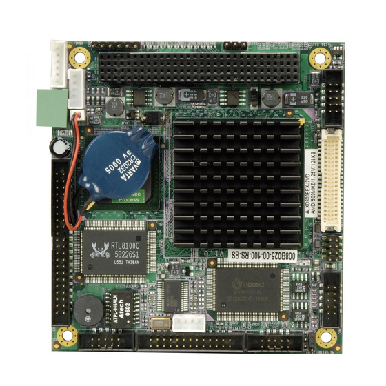
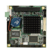
PC/104 AMD LX800 CPU Board with on-board TTL, VGA and USB2.0
Brand:
IEI Technology
| Category:
Motherboard
| Size: 8.08 MB
Table of Contents
Table of Contents
3
1 Introduction
13
Pm-Lx-800 Motherboard Introduction
14
PM-LX-800 Motherboard Applications
14
PM-LX-800 Motherboard Benefits
14
PM-LX-800 Motherboard Features
14
Pm-Lx-800 Motherboard Overview
15
Figure 1-1: PM-LX-800 Motherboard Overview (Front Side)
15
Figure 1-2: PM-LX-800 Motherboard Overview (Solder Side)
15
PM-LX-800 Motherboard Connectors
16
Technical Specifications
16
Table 1-1: Technical Specifications
17
2 Detailed Specifications
19
Cpu Support
20
System Chipset
21
Data Flow
23
Figure 2-1: Data Flow Block Diagram
23
Graphics Support
24
Table 2-1: Geode LX Graphics Processor Features
24
Memory Support
25
Pci Bus Interface Support
25
Ethernet
25
Drive Interfaces
26
Serial Ports
26
Real Time Clock
26
System Monitoring
27
Bios
27
Operating Temperature and Temperature Control
27
Power Consumption
28
PXE: Pre-Boot Execution Environment
28
Figure 2-2: PXE: Pre-Boot Execution Environment
28
Table 2-2: Power Consumption
28
Packaged Contents and Optional Accessory Items
29
Package Contents
29
3 Connectors and Jumpers
31
Peripheral Interface Connectors
32
Figure 3-1: Connector and Jumper Locations (Front Side)
32
PM-LX-800 Motherboard Layout
32
Figure 3-2: Connector and Jumper Locations (Solder Side)
33
Peripheral Interface Connectors
33
Onboard Jumpers
34
Internal Peripheral Connectors
34
5V Power Connector
34
Table 3-1: Peripheral Interface Connectors
34
Table 3-2: Onboard Jumper
34
Figure 3-3: 12V / 5V Power Connector Location
35
Input Connector
35
Table 3-3: 12V / 5V Power Connector Pinouts
35
Figure 3-4: 12V Input Connector Location
36
Table 3-4: 12V Input Connector Pinouts
36
200-Pin DDR SO-DIMM Socket
37
Table 3-5: 200-Pin DDR SO-DIMM Socket Pinouts
38
Battery Connector
39
Figure 3-5: 200-Pin DDR SO-DIMM Socket Location
39
Figure 3-6: Battery Connector Location
40
Table 3-6: Battery Connector Pinouts
40
Compactflash Connector
41
Figure 3-7: Compact Flash Connector Location
42
IDE Interface Connector
42
Table 3-7: Compactflash Connector Pinouts
42
Able 3-8: IDE Interface Connector Pinouts
43
Figure 3-8: IDE Interface Connector Location
44
Inverter Connector
44
Figure 3-9: Inverter Connector Location
45
Table 3-9: Inverter Connector Pinouts
45
Keyboard/Mouse Connector
46
Table 3-10: Keyboard/Mouse Connector Pinouts
46
Figure 3-10: Keyboard/Mouse Connector Location
47
LAN Connector
47
Figure 3-11: LAN Connector Location
48
Table 3-11: LAN Connector Pinouts
48
LED Power Connector
49
Table 3-12: LED Power Connector Pinouts
49
Figure 3-12: LED Power Connector Location
50
Parallel Port Connector
50
Table 3-13: Parallel Port Connector Pinouts
51
Connector
52
Figure 3-13: Parallel Port Connector Location
52
Table 3-14: PCI-104 Connector Pinouts
53
Figure 3-14: PCI-104 Connector Location
54
Serial Communications Connector
54
Figure 3-15 RS-232 Serial Communications Connector Locations
55
Table 3-15: RS-422 Serial Communications Connector Pinouts
55
RS-422/485 Serial Communications Connector
56
Table 3-16: RS-422/485 Serial Communications Connector Pinouts
56
Figure 3-16 RS-422/485 Serial Communications Connector Locations
57
TTL LCD Connector
57
Table 3-17: TTL LCD Connector Pinouts
58
Figure 3-17 TTL LCD Connector Locations
59
USB Connector
59
Figure 3-18 USB Connector Locations
60
Table 3-18: USB Connector Pinouts
60
Table 3-19: VGA Connector Pinouts
61
VGA Connector
61
Figure 3-19 VGA Connector Location
62
Figure 3-20: Jumper Locations
62
Onboard Jumpers
62
Figure 3-21: Jumper Locations
63
COM3 RS422/RS485 Select Jumper
64
Table 3-20: COM3 RS422/RS485 Select Jumper Settings
64
4 Installation and Configuration
65
Installation Considerations
66
Installation Notices
66
Unpacking
67
Unpacking Precautions
67
Checklist
68
Pm-Lx-800 Cpu Board Installation
68
DIMM Module Installation
69
Purchasing the Memory Module
69
SO-DIMM Module Installation
69
Compact Flash Disk Installation
70
Figure 4-1: SO-DIMM Module Installation
70
Peripheral Device Connection
70
Figure 4-2: Connection of IDE Connector
71
IDE Disk Drive Installation
71
Table 4-1: IEI Provided Cables
71
Chassis LED Installation
72
COM1/COM2 RS-232 Serial Port Installation
72
COM3 RS-422/485 Serial Port Installation
72
Keyboard/Mouse Installation
73
LAN Installation
73
LCD Backlight Installation
73
LPT Port Installation
74
Power Connection
74
TTL LCD Installation
74
USB Port Installation
74
Airflow Consideration
75
Mounting the PM-LX-800 Motherboard
75
VGA Port Installation
75
Jumper Configuration
76
Chassis Installation
76
5 Award Bios Setup
77
Introduction
78
Starting Setup
78
Using Setup
78
Getting Help
79
Table 5-1: BIOS Navigation Keys
79
Unable to Reboot after Configuration Changes
79
Main BIOS Menu
80
BIOS Menu 1: Awardbios CMOS Setup Utility
80
Exit Without Saving
81
Load Fail-Safe Defaults
81
Load Optimized Defaults
81
Save & Exit Setup
81
Set Supervisor Password
81
Set User Password
81
Standard Cmos Features
82
BIOS Menu 2: Standard CMOS Features
82
Date [Day MM:DD:yyyy]
82
IDE Master and IDE Slave
82
Time [Hh/MM/Ss]
82
Drive a [1.44M, 3.5In]
83
Halt on [All, but Keyboard]
83
Base Memory
84
Extended Memory
84
Total Memory
84
IDE Primary Master/Slave
85
BIOS Menu 3: IDE Primary Master
85
IDE HDD Auto-Detection [Press Enter]
85
IDE Primary Master [Auto]
85
Access Mode [Auto]
86
Capacity
86
Cylinder
87
Head
87
Landing Zone
87
Precomp
87
Sector
87
Advanced Bios Features
88
BIOS Menu 4: Advanced BIOS Features
88
Virus Warning [Disabled]
88
Boot Device
89
Boot from LAN Control [Disabled]
89
CPU Internal Cache [Enabled]
89
SATA Boot ROM Control [Disabled]
89
Boot Other Device [Enabled]
90
Boot up Floppy Seek [Disabled]
91
Boot up Numlock Status [On]
91
Gate A20 Option [Fast]
91
Typematic Rate Setting [Disabled]
91
Typematic Delay (Msec) [250]
92
Typematic Rate (Chars/Sec) [6]
92
Delay for HDD (Secs) [3]
93
OS Select for DRAM > 64MB [Non-OS2]
93
Security Option [Setup]
93
Small Logo (EPA) Show [Disabled]
94
Advanced Chipset Features
95
BIOS Menu 5: Advanced Chipset Features
95
CPU Frequency [500Mhz]
95
Memory Frequency [Auto]
95
CAS Latency [Auto]
96
Interleave Select [LOI]
96
Video Memory Size [8M]
96
Flat Panel Configuration [Press Enter]
97
Output Display [CRT]
97
Flat Panel Configuration
98
BIOS Menu 6: Flat Panel Configuration
98
Flat Panel Type [Auto]
98
Resolution [800 X 600]
98
Data Bus Type [9 - 24 Bits, 1 Ppc]
99
Refresh Rate [60Hz]
99
HSYNC Polarity [Low]
100
LP Active Period [Free Running]
100
SHFCLK Active Period [Free Running]
100
VSYNC Polarity Active [Low]
100
Integrated Peripherals
101
BIOS Menu 7: Integrated Peripherals
101
Drive PIO Mode [Auto]
101
On-Chip IDE Channel 1 [Enabled]
101
IDE DMA Transfer Access [Enabled]
102
IDE HDD Block Mode [Enabled]
102
IDE UDMA [Auto]
102
Onboard FDC Controller [Disabled]
103
Onboard Serial Port 1 [3F8/IRQ4]
103
Onboard Serial Port 2 [2F8/IRQ3]
103
Onboard Parallel Port [378/IRQ7]
104
Onboard Serial Port 3 [Disabled]
104
Parallel Port Mode [SPP]
104
ECP Mode Use DMA [3]
105
EPP Mode Select [EPP1.7]
105
Power Management Setup
106
BIOS Menu 8: Power Management Setup
106
ACPI Function [Disabled]
106
ACPI Suspend Type [S1&S3]
106
Power Management [APM]
107
Standby Mode [Disabled]
107
Soft-Off by PWR-BTTN [Instant-Off]
108
Suspend Mode [Disabled]
108
Pnp/Pci Configurations
109
BIOS Menu 9: Pnp/Pci Configurations
109
PNP os Installed [No]
109
Reset Configuration Data [Disabled]
109
Resources Controlled by [Auto (ESCD)]
110
BIOS Menu 10: IRQ Resources
111
IRQ Resources [Press Enter]
111
BIOS Menu 11: Memory Resources
112
Memory Resources [Press Enter]
112
Reserved Memory Base [N/A]
113
Reserved Memory Length [8K]
113
PCI/VGA Palette Snoop [Disabled]
114
Pc Health Status
115
BIOS Menu 12: PC Health Status
115
Shutdown Temperature
115
CPU Warning Temperature
116
Fan Speeds
116
Temperatures
116
Voltages
116
6 Software Drivers
117
Available Software Drivers
118
Figure 6-1: AMD LX/GX CD Main Menu
119
Figure 6-2: AMD LX/GX CD Driver Menu
120
Vga Driver
121
Figure 6-3: Access Windows Control Panel
121
Figure 6-4: Double Click the System Icon
122
Figure 6-5: Double Click the Device Manager Tab
122
Figure 6-6: Device Manager List
123
Figure 6-7: Expand the Display Adapters Category
124
Figure 6-8: Update Driver
125
Figure 6-9: Upgrade Device Driver Wizard
126
Figure 6-10: Search for Suitable Driver
127
Figure 6-11: Locate Driver Files
128
Figure 6-12: Location Browsing Window
128
Lan Driver
129
Figure 6-13: Locate the Setup Program Icon
129
Figure 6-14: Preparing Setup Screen
129
Figure 6-15: Install Wizard Welcome Screen
130
Figure 6-16: Installing Screen
131
Figure 6-17: Restart the Computer
132
Abios Configuration Options
133
A.1 BIOS Configuration Options
134
Bios Configuration Options
134
Bwatchdog Timer
137
Caddress Mapping
141
I/O Address Map
142
St Mb Memory Address Map
142
Irq Mapping Table
143
Dma Channel Assignments
143
Index
145
Advertisement
Advertisement
Related Products
IEI Technology PM-LX2-800W
IEI Technology PM-LX2-800
IEI Technology PM-LX2
IEI Technology PM-PV-N4551
IEI Technology PM-PV-D5251
IEI Technology PM-PV-D4251
IEI Technology PM-US15W
IEI Technology PM-945GSE-N270
IEI Technology PCIE-Q670-DVI-R10
IEI Technology PCIE-Q670-R20
IEI Technology Categories
Motherboard
Touch Panel
Computer Hardware
Single board computers
Desktop
More IEI Technology Manuals
Login
Sign In
OR
Sign in with Facebook
Sign in with Google
Upload manual
Upload from disk
Upload from URL