Sign In
Upload
Manuals
Brands
IEI Technology Manuals
Motherboard
PM-LX2-800W
IEI Technology PM-LX2-800W Manuals
Manuals and User Guides for IEI Technology PM-LX2-800W. We have
1
IEI Technology PM-LX2-800W manual available for free PDF download: User Manual
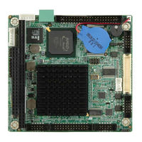
IEI Technology PM-LX2-800W User Manual (123 pages)
PC/104 SBC with AMD Geode LX800 500 MHz CPU, Ethernet, 2 USB 2.0, CF Card Type 2, RS-232, RS-422/485, RoHS Compliant
Brand:
IEI Technology
| Category:
Motherboard
| Size: 7 MB
Table of Contents
Table of Contents
4
User Manual
1
1 Introduction
11
Pm-Lx2-800 Introduction
12
Figure 1-1: PM-LX2-800
12
PM-L2X-800 Motherboard Applications
13
PM-LX2-800 Motherboard Benefits
13
PM-LX2-800 Motherboard Features
13
Pm-Lx2-800 Motherboard Overview
14
Figure 1-2: PM-LX2-800 Motherboard Overview
14
Figure 1-3: PM-LX2-800 Motherboard Solder Side Overview
15
PM-LX2-800 Motherboard Connectors
15
Dimensions
16
Figure 1-4: PM-LX2-800 Dimensions (MM)
16
Data Flow
17
Figure 1-5: Data Flow Block Diagram
17
Technical Specifications
18
Table 1-1: PM-LX2-800 Specifications
19
2 Unpacking
20
Anti-Static Precautions
21
Unpacking Precautions
21
Unpacking Checklist
22
Package Contents
22
Optional Items
23
Table 2-1: Package List Contents
23
Table 2-2: Package List Contents (Optional Items)
23
3 Connectors
24
Peripheral Interface Connectors
25
Figure 3-1: Connector and Jumper Locations (Front Side)
25
PM-LX2-800 Motherboard Layout
25
Figure 3-2: Connector and Jumper Locations (Solder Side)
26
Peripheral Interface Connectors
26
Internal Peripheral Connectors
27
5V Power Connector
27
Table 3-1: Peripheral Interface Connectors
27
12V / -5V Input Connector
28
Figure 3-3: 12V / 5V Power Connector Location
28
Table 3-2: 12V / 5V Power Connector Pinouts
28
200-Pin DDR SO-DIMM Socket
29
Figure 3-4: -12V Power Connector Location
29
Table 3-3: -12V Power Connector Pinouts
29
Figure 3-5: 200-Pin DDR SO-DIMM Socket Location
30
Table 3-4: 200-Pin DDR SO-DIMM Socket Pinouts
31
Battery Connector
32
Figure 3-6: Battery Connector Location
32
Compactflash® Connector
33
Figure 3-7: Compactflash® Connector Location
33
Table 3-5: Battery Connector Pinouts
33
Floppy Disk Connector
34
Table 3-6: Compactflash® Connector Pinouts
34
Figure 3-8: 26-Pin FDD Connector Location
35
Table 3-7: 26-Pin FDD Connector Pinouts
35
Figure 3-9: Primary IDE Device Connector Location
36
IDE Connector (Primary, 44-Pin)
36
Keyboard/Mouse Connector
37
Table 3-8: Primary IDE Connector Pinouts
37
Figure 3-10: Keyboard/Mouse Connector Location
38
LAN Connector
38
Table 3-9: Keyboard/Mouse Connector Pinouts
38
Figure 3-11: LAN Connector Location
39
LCD Inverter Connector
39
Table 3-10: LAN Connector Pinouts
39
Figure 3-12: LCD Inverter Connector Location
40
Led/Reset Button Connector
40
Table 3-11: LCD Inverter Connector Pinouts
40
Figure 3-13: LED Connector Location
41
Parallel Port Connector
41
Table 3-12: LED Connector Pinouts
41
Figure 3-14: Parallel Port Connector Location
42
Table 3-13: Parallel Port Connector Pinouts
42
Figure 3-15: PC/104 Slot Location
43
PC/104 Slot
43
Serial Port Connectors
44
Table 3-14: PC/104 Slot Connector Pinouts
44
Figure 3-16: RS-232 Serial Port Connector Locations
45
RS-422/485 Serial Port Connector
45
Table 3-15: RS-232 Serial Port Connector Pinouts
45
Figure 3-17: RS-422/485 Serial Port Connector Location
46
Table 3-16: RS-422/RS-485 Serial Port Connector Pinouts
46
TTL LCD Connector
46
Figure 3-18: TTL Connector Locations
47
Table 3-17: TTL Connector Pinouts
47
Figure 3-19: USB Connector Pinout Locations
48
Table 3-18: USB Port Connector Pinouts
48
USB Connector
48
VGA Connector
48
Figure 3-20: VGA Connector Location
49
Table 3-19: VGA Connector Pinouts
49
4 Installation
50
Anti-Static Precautions
51
Installation Considerations
52
Installation Notices
52
Installation Checklist
53
Unpacking
54
SO-DIMM and Compactflash® Installation
54
SO-DIMM Module Installation
55
Compactflash® Card Installation
55
Figure 4-1: SO-DIMM Module Installation
55
Jumper Settings
56
Figure 4-2: Compactflash® Card Installation
56
Figure 4-3: Jumper Locations
57
COM3 RS422/RS485 Select Jumper
58
LCD Voltage Select Jumper
58
Table 4-1: COM3 RS422/RS485 Select Jumper Settings
58
Table 4-2: LCD Voltage Select Jumper Settings
58
Chassis Installation
59
Internal Peripheral Device Connections
59
Table 4-3: IEI Provided Cables
59
ATA Flat Cable Connection
60
Figure 4-4: IDE Cable Connection
60
Figure 4-5: Keyboard/Mouse Y-Cable Connection
61
Keyboard/Mouse Y-Cable Connector
61
Parallel Port Cable Without Bracket
62
Figure 4-6: LPT Cable Connection
63
Figure 4-7: Connect the LPT Device
63
Figure 4-8: Single RS-232 Cable Installation
64
Single RS-232 Cable (Without Bracket)
64
TFT LCD Installation
65
Figure 4-9: TTL Connector
66
Figure 4-10: Backlight Inverter Connection
67
5 Bios
68
Introduction
69
Starting Setup
69
Using Setup
69
BIOS Menu Bar
70
Getting Help
70
Table 5-1: BIOS Navigation Keys
70
Unable to Reboot after Configuration Changes
70
Main
71
BIOS Menu 1: Main
71
System Overview
71
Advanced
72
System Date [XX/XX/XX]
72
System Time [XX:XX:XX]
72
CPU Configuration
73
BIOS Menu 2: Advanced
73
BIOS Menu 3: CPU Configuration
73
IDE Configuration
74
BIOS Menu 4: IDE Configuration
74
ATA/IDE Configurations [Compatible]
74
Configure SATA as [IDE]
75
Configure SATA Channels [Behind PATA]
75
Legacy IDE Channels [PATA Pri, SATA Sec]
75
Onboard PCI IDE Controller [Both]
75
Hard Disk Write Protect [Disabled]
76
IDE Master and IDE Slave
76
IDE Master, IDE Slave
77
BIOS Menu 5: IDE Master and IDE Slave Configuration
77
Auto-Detected Drive Parameters
77
Lba/Large Mode [Auto]
78
Type [Auto]
78
Block (Multi Sector Transfer) [Auto]
79
PIO Mode [Auto]
79
DMA Mode [Auto]
80
32Bit Data Transfer [Enabled]
81
Auto]
81
Floppy Configuration
81
Super I/O Configuration
82
BIOS Menu 6: IDE Master and IDE Slave Configuration
82
Floppy A/B
82
BIOS Menu 7: Super IO Configuration
83
Serial Port1 Address [3F8]
83
Serial Port1 IRQ [4]
83
Serial Port2 Address [2F8]
84
Serial Port2 IRQ [4]
84
Serial Port3 Address [3E8]
84
Serial Port3 IRQ [3]
84
Parallel Port Address [Disabled]
85
Parallel Port Mode [Normal]
85
Hardware Health Configuration
86
Parallel Port IRQ [IRQ7]
86
Remote Access Configuration
87
BIOS Menu 8: Hardware Health Configuration
87
Hardware Health Monitoring
87
BIOS Menu 9: Remote Access Configuration
88
Remote Access [Disabled]
88
Base Address, IRQ [3F8H,4]
89
Detected Serial Port R [1]
89
Redirection after BIOS POST [Always]
89
Serial Port Mode [115200 8,N,1]
89
USB Configuration
90
BIOS Menu 10: USB Configuration
90
Terminal Type [ANSI]
90
Legacy USB Support [Enabled]
91
USB 1.1 Controller [Enabled]
91
USB 2.0 Controller [Enabled]
91
USB Configuration
91
USB Devices Enabled
91
IT8888 ISA Decode IO Spaces
92
BIOS Menu 11: IT8888 ISA Decode IO
92
Decode IO Space X [Disabled]
92
Decode IO Address X [15:0] [Varying Defaults]
93
Decode IO Size X [Varying Defaults]
93
Decode IO Speed X [Slow Speed]
93
IT8888 ISA Decode Memory
93
BIOS Menu 12: IT8888 ISA Decode Memory
94
Decode Memory Space X [Disabled]
94
Decode Memory Speed X [Medium Speed]
94
Decode Memory Address X [Varying Defaults]
95
Decode Memory Size X [Varying Defaults]
95
Pci/Pnp
95
BIOS Menu 13: Pci/Pnp Configuration
96
IRQ# [Available]
96
DMA Channel# [Available]
97
Reserved Memory Size [Disabled]
97
Boot
98
Boot Settings Configuration
98
BIOS Menu 14: Boot
98
BIOS Menu 15: Boot Settings Configuration
98
Addon ROM Display Mode [Force BIOS]
99
Bootup Num-Lock [On]
99
Quick Boot [Enabled]
99
Quiet Boot [Disabled]
99
Boot Device Priority
100
BIOS Menu 16: Boot Device Priority Settings
100
Spread Spectrum Mode [Disabled]
100
Hard Disk Drives
101
Removable Drives
101
BIOS Menu 17: Hard Disk Drives
101
CD/DVD Drives
102
BIOS Menu 18: Removable Drives
102
Security
103
BIOS Menu 19: CD/DVD Drives
103
BIOS Menu 20: Security
103
Change Supervisor Password
103
Boot Sector Virus Protection [Disabled]
104
Change User Password
104
Chipset
104
Clear User Password
104
Video Configuration
105
BIOS Menu 21: Chipset
105
BIOS Menu 22: Video Configuration
105
Boot Display Device [Panel + CRT]
106
Flat Panel Resolution [800 X 600]
106
Flat Panel Type [Auto]
106
Internal Graphics Memory [32 MB]
106
Flat Panel Data Bus Type [9 - 24 Bits, 1 Ppc]
107
Horizontal Sync Polarity [Low]
107
Refresh Rate [60Hz]
107
Exit
108
BIOS Menu 23:Exit
108
Vertical Sync Polarity [Low]
108
ABIOS Options
110
Appendix A
111
B Terminology
114
C Watchdog Timer
117
D Hazardous Materials Disclosure
120
Hazardous Materials Disclosure Table for IPB Products Certified as Rohs Compliant under 2002/95/EC Without Mercury
121
Advertisement
Advertisement
Related Products
IEI Technology PM-LX2-800
IEI Technology PM-LX2
IEI Technology PM-LX-800
IEI Technology PM-PV-N4551
IEI Technology PM-PV-D5251
IEI Technology PM-PV-D4251
IEI Technology PM-US15W
IEI Technology PM-945GSE-N270
IEI Technology POS-478
IEI Technology PICO-8522
IEI Technology Categories
Motherboard
Touch Panel
Computer Hardware
Single board computers
Desktop
More IEI Technology Manuals
Login
Sign In
OR
Sign in with Facebook
Sign in with Google
Upload manual
Upload from disk
Upload from URL