Sign In
Upload
Manuals
Brands
IEI Technology Manuals
Motherboard
NANO-ULT5
IEI Technology NANO-ULT5 Manuals
Manuals and User Guides for IEI Technology NANO-ULT5. We have
1
IEI Technology NANO-ULT5 manual available for free PDF download: User Manual
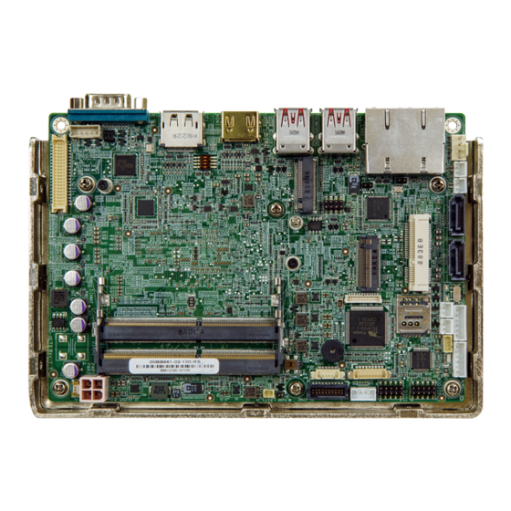
IEI Technology NANO-ULT5 User Manual (147 pages)
EPIC SBC with 14nm Intel Core i7/i5/i3 or Celeron On-board SoC, LVDS, HDMI, DP, Dual PCIe GbE, USB 3.1 Gen 2, M.2, PCIe Mini, SATA 6Gb/s, RS-232/422/485, Audio, TPM and RoHS
Brand:
IEI Technology
| Category:
Motherboard
| Size: 5.9 MB
Table of Contents
Table of Contents
5
1 Introduction
15
Ntroduction
16
Figure 1-1: NANO-ULT5
16
Model Variations
17
Features
17
Table 1-1: NANO-ULT5 Model Variations
17
Connectors
18
Figure 1-2: Connectors
18
Dimensions
19
Figure 1-3: Dimensions (MM)
19
Data Flow
20
Figure 1-4: Data Flow Diagram
20
Technical Specifications
21
Table 1-2: Technical Specifications
23
2 Unpacking
24
Anti-Static Precautions
25
Unpacking Precautions
25
Packing List
26
Optional Items
27
3 Connectors
28
Peripheral Interface Connectors
29
NANO-ULT5 Layout
29
Figure 3-1: Connector and Jumper Locations
29
Peripheral Interface Connectors
30
External Interface Panel Connectors
31
Table 3-1: Peripheral Interface Connectors
31
Table 3-2: Rear Panel Connectors
31
Internal Peripheral Connectors
32
Audio Connector
32
Figure 3-2: Audio Connector Location
32
Table 3-3: Audio Connector Pinouts
32
Battery Connector
33
Figure 3-3: Battery Connector Location
34
Table 3-4: Battery Connector Pinouts
34
Digital I/O Connector
35
Figure 3-4: Digital I/O Connector Location
35
Table 3-5: Digital I/O Connector Pinouts
35
Fan Connector
36
Figure 3-5: Fan Connector Location
36
Table 3-6: Fan Connector Pinouts
36
Front Panel Connector
37
Figure 3-6: Front Panel Connector Location
37
Table 3-7: Front Panel Connector Pinouts
37
Keyboard and Mouse Connector
38
Figure 3-7: Keyboard and Mouse Connector Location
38
Table 3-8: Keyboard and Mouse Connector Pinouts
38
LAN LED Connectors
39
LVDS LCD Connector
39
Figure 3-8: LAN LED Connector Locations
39
Table 3-9: LAN LED Connector Pinouts
39
Figure 3-9: LVDS Connector Location
40
Table 3-10: LVDS Connector Pinouts
40
LVDS Backlight Inverter Connector
41
Figure 3-10: Backlight Inverter Connector Location
41
Table 3-11: Backlight Inverter Connector Pinouts
41
Slot, A-Key
42
Figure 3-11: M.2 A-Key Slot Location
42
Table 3-12: M.2 A-Key Slot Pinouts
43
Slot, M-Key
44
Figure 3-12: M.2 M-Key Slot Location
44
Table 3-13: M.2 M-Key Slot Pinouts
45
DDR4 SO-DIMM Sockets
46
Pcie Mini Card Slot, Full-Size
46
Figure 3-13: DDR4 SO-DIMM Socket Locations
46
Figure 3-14: Full-Size Pcie Mini Card Slot Location
47
Power Connector
48
Figure 3-15: +12V DC-IN Power Connector Location
48
Table 3-14: Full-Size Pcie Mini Card Slot Pinouts
48
Table 3-15: +12V DC-IN Power Connector Pinouts
48
Power Button Connector
49
Figure 3-16: Power Button Connector Location
49
Table 3-16: Power Button Connector Pinouts
49
Reset Button Connector
50
Figure 3-17: Reset Button Connector Location
50
Table 3-17: Reset Button Connector Pinouts
50
Serial Port Connector
51
Figure 3-18: RS-232 Serial Port Connector Location
51
Table 3-18: RS-232 Serial Port Connector Pinouts
51
RS-422/485 Serial Port Connector
52
Figure 3-19: RS-422/485 Connector Location
52
Table 3-19: RS-422/485 Connector Pinouts
52
SATA 6Gb/S Drive Connectors
53
Figure 3-20: SATA 6Gb/S Drive Connectors Locations
53
SATA Power Connectors
54
Figure 3-21: SATA Power Connector Locations
54
Table 3-20: SATA Power Connector Pinouts
54
Smbus/I C Connector
55
Figure 3-22: Smbus Connector Location
55
Table 3-21: Smbus Connector Pinouts
55
SIM Card Slot
56
Figure 3-23: SIM Card Slot Location
56
SPI Flash Connector
57
Figure 3-24: SPI Flash Connector Location
57
Table 3-22: SPI Flash Connector Pinouts
57
TPM Connector
58
Figure 3-25: TPM Connector Pinout Locations
58
Table 3-23: TPM Connector Pinouts
58
USB 2.0 Connector
59
Figure 3-26: USB Connector Location
59
Table 3-24: USB Connector Pinouts
59
External Peripheral Interface Connector Panel
60
Figure 3-27: External Peripheral Interface Connector
60
Displayport Connector
61
Figure 3-28: Displayport Connector Pinout Locations
61
Table 3-25: Displayport Connector Pinouts
61
Figure 3-29: HDMI Connector Pinout Locations
62
HDMI Connector
62
Table 3-26: HDMI Connector Pinouts
62
Figure 3-30: LAN Connector
63
LAN Connectors
63
Table 3-27: LAN Pinouts
63
Table 3-28: LAN Connector Leds
63
Figure 3-31: Serial Port Pinouts
64
Serial Port Connector
64
Table 3-29: Serial Port Pinouts
64
Figure 3-32: USB 3.1 Gen 2 Port Pinouts
65
Table 3-30: USB 3.1 Gen 2 Port Pinouts
65
USB 3.1 Gen 2 Connectors
65
4 Installation
66
Anti-Static Precautions
67
Installation Considerations
67
So-DIMM Installation
69
Figure 4-1: SO-DIMM Installation
69
Module Installation
70
Figure 4-2: Inserting the M.2 Module into the Slot at an Angle
70
Figure 4-3: Securing the M.2 Module
70
M.2 M Odule I Nstallation
70
Pcie Mini Card Installation
71
Figure 4-4: Removing the Retention Screw
71
Figure 4-5: Inserting the Full-Size Pcie Mini Card into the Slot at an Angle
71
Sim Card Installation
72
Figure 4-6: Securing the Full-Size Pcie Mini Card
72
Figure 4-7: Unlock SIM Card Slot Cover
72
Figure 4-8: SIM Card Installation
73
Figure 4-9: Lock SIM Card Slot Cover
73
System Configuration
74
AT/ATX Mode Select Switch
74
Figure 4-10: AT/ATX Mode Select Switch Location
74
Table 4-1: AT/ATX Mode Select Switch Settings
74
Clear CMOS Button
75
Figure 4-11: Clear CMOS Button Location
75
Backlight Mode Select Jumper
76
Figure 4-12: Backlight Mode Select Jumper Location
76
Table 4-2: Backlight Mode Select Jumper Settings
76
Flash Descriptor Security Override Jumper
77
Figure 4-13: Flash Descriptor Security Override Jumper Location
77
Table 4-3: Flash Descriptor Security Override Jumper Settings
77
LCD Voltage Selection
78
Table 4-4: LCD Voltage Selection Jumper Settings
78
LVDS Panel Resolution Select Switch
79
Figure 4-14: LCD Voltage Selection Jumper Location
79
Figure 4-15: LVDS Panel Resolution Select Switch Location
80
Table 4-5: LVDS Panel Resolution Selection
80
Chassis Installation
81
Heat Spreader
81
Motherboard Installation Example
82
Figure 4-16: Heat Sink Retention Screws
82
Figure 4-17: Motherboard Installation Example
82
Internal Peripheral Device Connections
83
AT Power Connection
83
Figure 4-18: Power Cable to Motherboard Connection
83
Audio Kit Installation
84
Figure 4-19: Connect Power Cable to Power Supply
84
Cable Connection
85
Figure 4-20: Audio Kit Cable Connection
85
SATA Drive Connection
86
Figure 4-21: Single RS-232 Cable Installation
86
Figure 4-22: SATA Drive Cable Connection
87
Intel ® Amt Setup Procedure
88
5 Bios
89
Introduction
90
Starting Setup
90
Using Setup
90
Getting Help
91
Unable to Reboot after Configuration Changes
91
BIOS Menu Bar
91
Main
92
BIOS Menu 1: Main
92
Advanced
93
BIOS Menu 2: Advanced
93
CPU Configuration
94
BIOS Menu 3: CPU Configuration
94
PCH-FW Configuration
96
BIOS Menu 4: PCH-FW Configuration
96
Trusted Computing
97
BIOS Menu 5: Trusted Computing
97
ACPI Settings
98
BIOS Menu 6: ACPI Settings
98
RTC Wake Settings
99
BIOS Menu 7: RTC Wake Settings
99
Iwdd H/W Monitor
100
BIOS Menu 8: Iwdd H/W Monitor
100
Smart Fan Mode Configuration
101
BIOS Menu 9: Smart Fan Mode Configuration
101
F81866 Super IO Configuration
103
BIOS Menu 10: F81866 Super IO Configuration
103
Serial Port N Configuration
104
BIOS Menu 11: Serial Port N Configuration
104
Serial Port Console Redirection
105
BIOS Menu 12: Serial Port Console Redirection
105
Legacy Console Redirection Settings
106
BIOS Menu 13: Legacy Console Redirection Settings
106
Console Redirection Settings
107
BIOS Menu 14: Console Redirection Settings
107
USB Configuration
109
BIOS Menu 15: USB Configuration
109
CSM Configuration
110
BIOS Menu 16: CSM Configuration
110
Nvme Configuration
111
BIOS Menu 17: Nvme Configuration
111
IEI Feature
112
BIOS Menu 18: IEI Feature
112
Chipset
113
System Agent (SA) Configuration
113
BIOS Menu 19: Chipset
113
BIOS Menu 20: System Agent (SA) Configuration
113
Memory Configuration
114
BIOS Menu 21: Memory Configuration
114
Graphics Configuration
115
BIOS Menu 22: Graphics Configuration
115
PCH-IO Configuration
117
BIOS Menu 23: PCH-IO Configuration
117
PCI Express Configuration
119
M2_A1 / MINI_PCIE1 / M2_M2 Configuration
119
BIOS Menu 24: PCI Express Configuration
119
BIOS Menu 25: M2_A1 / MINI_PCIE1 / M2_M2 Configuration
119
SATA and RST Configuration
121
BIOS Menu 26: SATA and RST Configuration
121
Security
123
BIOS Menu 27: Security
123
Boot
124
BIOS Menu 28: Boot
124
Exit
126
BIOS Menu 29: Exit
126
6 Software Drivers
128
Available Drivers
129
Driver Download
129
Figure 6-1: IEI Resource Download Center
129
A Regulatory Compliance
132
B Product Disposal
134
CBIOS Menu Options
136
D Digital I/O Interface
139
E Watchdog Timer
142
F Hazardous Materials Disclosure
145
Advertisement
Advertisement
Related Products
IEI Technology NANO-GM45A
IEI Technology NANO-945GSE3
IEI Technology Nano-PV-N4551
IEI Technology Nano-PV-D5251
IEI Technology NANO-QM871
IEI Technology NANO-9452
IEI Technology NANO-QM871-i1
IEI Technology NANO-CV-D25501
IEI Technology NANO-4386A2
IEI Technology NANO-HM551-R10
IEI Technology Categories
Motherboard
Touch Panel
Computer Hardware
Single board computers
Desktop
More IEI Technology Manuals
Login
Sign In
OR
Sign in with Facebook
Sign in with Google
Upload manual
Upload from disk
Upload from URL