Sign In
Upload
Manuals
Brands
IEI Technology Manuals
Motherboard
Nano-PV-N4551
IEI Technology Nano-PV-N4551 Manuals
Manuals and User Guides for IEI Technology Nano-PV-N4551. We have
1
IEI Technology Nano-PV-N4551 manual available for free PDF download: User Manual
IEI Technology Nano-PV-N4551 User Manual (153 pages)
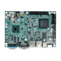
EPIC motherboard with Intel Atom processor VGA, LVDS GbE LAN, Eight USB 2.0. Two SATA 3Gb/s, Three RS-232, RS-232/422/485, PCIe mini, PCI-104, Parallel port
Brand:
IEI Technology
| Category:
Motherboard
| Size: 7.38 MB
Table of Contents
User Manual
1
Table of Contents
4
1 Introduction
14
Introduction
15
Connectors
15
Figure 1-1: NANO-PV-D4251/N4551/D5251
15
Figure 1-2: Connectors
16
Dimensions
17
Figure 1-3: NANO-PV-D4251/N4551/D5251 Dimensions (MM)
17
Data Flow
18
Figure 1-4: Data Flow Block Diagram
18
Technical Specifications
19
Table 1-1: Technical Specifications
21
2 Unpacking
22
Anti-Static Precautions
23
Unpacking Precautions
23
Packing List
24
Optional Items
25
3 Connectors
26
Peripheral Interface Connectors
27
NANO-PV-D4251/N4551/D5251 Layout
27
Figure 3-1: Connector and Jumper Locations
27
Peripheral Interface Connectors
28
External Interface Panel Connectors
29
Internal Peripheral Connectors
29
Table 3-1: Peripheral Interface Connectors
29
Table 3-2: Rear Panel Connectors
29
Audio Connector
30
Battery Connector
30
Figure 3-2: Audio Connector Location
30
Table 3-3: Audio Connector Pinouts
30
Compactflash® Slot
31
Figure 3-3: Battery Connector Location
31
Figure 3-4: Compactflash® Slot Location
31
Table 3-4: Battery Connector Pinouts
31
Digital I/O Connector
32
Table 3-5: Compactflash® Slot Pinouts
32
Fan Connector (CPU)
33
Figure 3-5: Digital I/O Connector Locations
33
Figure 3-6: CPU Fan Connector Location
33
Table 3-6: Digital I/O Connector Pinouts
33
Table 3-7: CPU Fan Connector Pinouts
33
Fan Connector (System)
34
Figure 3-7: +12V Fan Connector Locations
34
Front Panel Connector
34
Table 3-8: +12V Fan Connector Pinouts
34
Figure 3-8: Front Panel Connector Location
35
Keyboard/Mouse Connector
35
Table 3-9: Front Panel Connector Pinouts
35
Backlight Inverter Connector
36
Figure 3-10: Backlight Inverter Connector Location
36
Figure 3-9: Keyboard/Mouse Connector Location
36
Table 3-10: Keyboard/Mouse Connector Pinouts
36
Figure 3-11: LVDS1 Connector Locations
37
LVDS1 LCD Connector
37
Table 3-11: Backlight Inverter Connector Pinouts
37
Table 3-12: LVDS2 Connector Pinouts
37
Figure 3-12: Parallel Port Connector Location
38
Parallel Port Connector
38
Table 3-13: Parallel Port Connector Pinouts
38
Connector
39
Figure 3-13: PCI-104 Connector Location
39
Figure 3-14: Pcie Mini Card Slot Location
40
Pcie Mini Card Slot
40
Table 3-14: PCI-104 Connector Pinouts
40
Table 3-15: Pcie Mini Card Slot Pinouts
41
Figure 3-15: CPU 12V Power Connector Location
42
Power Connector
42
SATA Drive Connectors
42
Table 3-16: CPU 12V Power Connector Pinouts
42
Figure 3-16: SATA Drive Connector Locations
43
Figure 3-17: SATA Power Connector Locations
43
SATA Power Connector
43
Table 3-17: SATA Drive Connector Pinouts
43
Figure 3-18: COM Connector Pinout Locations
44
Serial Port Connectors (RS-232)
44
Table 3-18: SATA Power Connector Pinouts
44
Figure 3-19: Serial Port Connector Location
45
Serial Port Connector (RS-232/422/485)
45
Smbus Connector
45
Table 3-19: COM Connector Pinouts
45
Table 3-20: Serial Port Connector Pinouts
45
Figure 3-20: Smbus Connector Locations
46
Figure 3-21: SPI Flash Connector
46
SPI Flash Connector
46
Table 3-21: Smbus Connector Pinouts
46
Figure 3-22: TPM Connector Pinout Locations
47
Table 3-22: SPI Flash Connector Pinouts
47
TPM Connector
47
Figure 3-23: USB Connector Pinout Locations
48
Table 3-23: TPM Connector Pinouts
48
Table 3-24: USB Port Connector Pinouts
48
USB Connectors
48
External Peripheral Interface Connector Panel
49
Ethernet Connector
49
Figure 3-24: NANO-PV-D4251/N4551/D5251 External Peripheral Interface Connector
49
Keyboard/Mouse Connector
50
Figure 3-25: RJ-45 Ethernet Connector
50
Table 3-25: LAN Pinouts
50
Table 3-26: RJ-45 Ethernet Connector Leds
50
USB Connectors
51
Figure 3-26: PS/2 Pinout and Configuration
51
Table 3-27: Keyboard Connector Pinouts
51
Table 3-28: USB Port Connector Pinouts
51
VGA Connector
52
Figure 3-27: VGA Connector
52
Table 3-29: VGA Connector Pinouts
52
4 Installation
53
Anti-Static Precautions
54
Installation Considerations
55
Installation Notices
55
Unpacking
56
So-DIMM Installation
56
SO-DIMM Installation
57
Jumper Settings
57
Figure 4-1: SO-DIMM Installation
57
AT Auto Button Power Select Jumper Settings
58
Table 4-1: Jumpers
58
Table 4-2: at Auto Button Power Select Jumper Settings
58
AT/ATX Power Select Jumper Settings
59
Figure 4-2: at Auto Button Select Jumper Settings
59
Figure 4-3: AT/ATX Power Select Jumper Location
59
Table 4-3: AT/ATX Power Select Jumper Settings
59
Clear CMOS Jumper
60
Table 4-4: Clear CMOS Jumper Settings
60
COM 3 Function Select Jumper
61
Figure 4-4: Clear CMOS Jumper
61
Figure 4-5: COM 3 Function Select Jumper Location
61
Table 4-5: COM 3 Function Select Jumper Settings
61
COM 3 RS-422/485 Function Select Jumper
62
Compactflash® Card Setup
62
Figure 4-6: COM 3 RS-422/485 Function Select Jumper Location
62
Table 4-6: COM 3 RS-422/485 Function Select Jumper Settings
62
Compactflash® Voltage Selection
63
Figure 4-7: Compactflash® Setup Jumper Location
63
Table 4-7: Compactflash® Setup Jumper Settings
63
Table 4-8: Compactflash® Voltage Selection Jumper Settings
63
Figure 4-8: Compactflash® Voltage Selection Jumper Location
64
Figure 4-9: LVDS Screen Resolution Jumper Locations
64
LVDS1 Screen Resolution Selection
64
Table 4-9: LVDS1 Screen Resolution Jumper Settings
64
Figure 4-10: LVDS Voltage Selection Jumper Locations
65
LVDS Voltage Selection
65
Table 4-10: LVDS Voltage Selection Jumper Settings
65
Voltage Setup
65
Chassis Installation
66
Airflow
66
Figure 4-11: PCI-104 Voltage Jumper Location
66
Table 4-11: PCI-104 Voltage Jumper Settings
66
Motherboard Installation
67
Internal Peripheral Device Connections
67
AT/ATX Power Connection
67
Figure 4-12: Power Cable to Motherboard Connection
68
Audio Kit Installation
69
Figure 4-13: Connect Power Cable to Power Supply
69
Single RS-232 Cable (W/O Bracket)
70
Figure 4-14: Audio Kit Cable Connection
70
External Peripheral Interface Connection
71
Figure 4-15: Single RS-232 Cable Installation
71
Figure 4-16: LAN Connection
72
LAN Connection (Single Connector)
72
PS/2 Y-Cable Connection
72
Figure 4-17: PS/2 Keyboard/Mouse Connector
73
Serial Device Connection
73
Figure 4-18: Serial Device Connector
74
USB Connection (Dual Connector)
74
Figure 4-19: USB Connector
75
VGA Monitor Connection
75
Software Installation
76
Figure 4-20: VGA Connector
76
Figure 4-21: Introduction Screen
77
Figure 4-22: Available Drivers
78
5 Bios Screens
79
Introduction
80
Starting Setup
80
Using Setup
80
Getting Help
81
Unable to Reboot after Configuration Changes
81
BIOS Menu Bar
81
Table 5-1: BIOS Navigation Keys
81
Main
82
BIOS Menu 1: Main
82
Advanced
83
ACPI Settings
83
BIOS Menu 2: Advanced
83
Trusted Computing
84
BIOS Menu 3: ACPI Settings
84
CPU Configuration
85
BIOS Menu 4: TPM Configuration
85
BIOS Menu 5: CPU Configuration
86
SATA Configuration
87
BIOS Menu 6: IDE Configuration
87
USB Configuration
88
BIOS Menu 7: USB Configuration
88
Super IO Configuration
89
BIOS Menu 8: Super IO Configuration
89
Serial Port N Configuration
90
BIOS Menu 9: Serial Port N Configuration Menu
90
Irda Configuration
95
BIOS Menu 10: Irda Configuration Menu
95
Parallel Port Configuration
96
BIOS Menu 11: Parallel Port Configuration Menu
96
H/W Monitor
97
BIOS Menu 12: Hardware Health Configuration
98
Serial Port Console Redirection
99
BIOS Menu 13: Serial Port Console Redirection
99
Chipset
100
BIOS Menu 14: Chipset
100
Host Bridge Configuration
101
BIOS Menu 15: Host Bridge Chipset Configuration
101
Onchip VGA Configuration
102
BIOS Menu 16: Onchip VGA Configuration
102
South Bridge Configuration
103
BIOS Menu 17: South Bridge Chipset Configuration
103
Intel IGD SWSCI Opregion
104
BIOS Menu 18: South Bridge Chipset Configuration
104
Boot
106
BIOS Menu 19: Boot
106
Security
107
BIOS Menu 20: Security
108
Exit
109
BIOS Menu 21:Exit
109
ABIOS Menu Options
111
B One Key Recovery
114
One Key Recovery Introduction
115
B.1 O Ne K Ey R Ecovery I Ntroduction
115
Figure B-1: IEI One Key Recovery Tool Menu
115
System Requirement
116
Supported Operating System
117
Setup Procedure for Windows
118
Hardware and BIOS Setup
118
Create Partitions
119
Figure B-2: Launching the Recovery Tool
119
Figure B-3: Recovery Tool Setup Menu
120
Figure B-4: Command Mode
120
Figure B-5: Partition Creation Commands
121
Install Operating System, Drivers and Applications
122
Build-Up Recovery Partition
123
Figure B-6: Launching the Recovery Tool
123
Figure B-7: System Configuration for Windows
123
Figure B-8: Build-Up Recovery Partition
124
Figure B-9: Press any Key to Continue
124
Create Factory Default Image
125
Figure B-10: Press F3 to Boot into Recovery Mode
125
Figure B-11: Recovery Tool Menu
125
Figure B-12: about Symantec Ghost Window
126
Figure B-13: Symantec Ghost Path
126
Figure B-14: Select a Local Source Drive
127
Figure B-15: Select a Source Partition from Basic Drive
127
Figure B-16: File Name to Copy Image to
128
Figure B-17: Compress Image
128
Figure B-18: Image Creation Confirmation
129
Figure B-19: Image Creation Complete
129
Figure B-20: Image Creation Complete
129
Setup Procedure for Linux
130
Figure B-21: Press any Key to Continue
130
Figure B-22: Partitions for Linux
131
Figure B-23: System Configuration for Linux
132
Figure B-24: Access Menu.lst in Linux (Text Mode)
132
Recovery Tool Functions
133
Figure B-25: Recovery Tool Menu
133
B.4 R Ecovery T Ool F Unctions
133
Figure B-26: Recovery Tool Main Menu
134
Factory Restore
135
Figure B-27: Restore Factory Default
135
Figure B-28: Recovery Complete Window
135
Backup System
136
Figure B-29: Backup System
136
Figure B-30: System Backup Complete Window
136
Figure B-31: Restore Backup
137
Figure B-32: Restore System Backup Complete Window
137
Restore Your Last Backup
137
Figure B-33: Symantec Ghost Window
138
Manual
138
Other Information
139
Using AHCI Mode or Ali M5283 / VIA VT6421A Controller
139
B.5 O Ther I Nformation
139
System Memory Requirement
141
C Terminology
142
D Watchdog Timer
147
E Hazardous Materials Disclosure
150
Hazardous Material Disclosure Table for IPB Products Certified as Rohs Compliant under 2002/95/EC Without Mercury
151
E.1 H Azardous M Aterial D Isclosure T Able for Ipb P Roducts C Ertified as R O Hs C Ompliant U Nder 2002/95/Ec W Ithout M Ercury
151
Advertisement
Advertisement
Related Products
IEI Technology NANO-PV-N4552
IEI NANO-PV-N4551-R10
IEI Technology NANO-PV-N4552-R10
IEI Technology NANO-PV-D510A
IEI Technology NANO-PV-D4252
IEI Technology NANO-PV-D5252
IEI Technology Nano-PV-D4251
IEI Technology Nano-PV-D5251
IEI Technology NANO-PV-D4251-R10
IEI Technology NANO-PV-D5251-R10
IEI Technology Categories
Motherboard
Touch Panel
Computer Hardware
Single board computers
Desktop
More IEI Technology Manuals
Login
Sign In
OR
Sign in with Facebook
Sign in with Google
Upload manual
Upload from disk
Upload from URL