Sign In
Upload
Manuals
Brands
IEI Technology Manuals
Motherboard
KINO-PV-D4252
IEI Technology KINO-PV-D4252 Manuals
Manuals and User Guides for IEI Technology KINO-PV-D4252. We have
2
IEI Technology KINO-PV-D4252 manuals available for free PDF download: User Manual
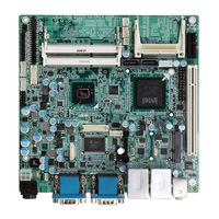
IEI Technology KINO-PV-D4252 User Manual (163 pages)
Mini ITX SBC with Intel Atom processor D425/D525, DDR3 VGA, Dual LVDS, Dual GbE LAN, USB 2.0, SATA 3Gb/s, RoHS
Brand:
IEI Technology
| Category:
Motherboard
| Size: 7.74 MB
Table of Contents
Table of Contents
4
User Manual
1
1 Introduction
15
Introduction
16
Figure 1-1: KINO-PV-D5252/D4252
16
Connectors
17
Figure 1-2: Connectors
17
Dimensions
18
Figure 1-3: KINO-PV-D5252/D4252 Dimensions (MM)
18
Data Flow
19
Figure 1-4: Data Flow Block Diagram
19
Technical Specifications
20
Table 1-1: Technical Specifications
21
2 Unpacking
22
Anti-Static Precautions
23
Unpacking Precautions
23
Packing List
24
Optional Items
25
3 Connectors
26
Peripheral Interface Connectors
27
Figure 3-1: Connector and Jumper Locations
27
KINO-PV-D5252/D4252 Layout
27
Peripheral Interface Connectors
28
External Interface Panel Connectors
29
Internal Peripheral Connectors
29
Power Connector
29
Table 3-1: Peripheral Interface Connectors
29
Table 3-2: Rear Panel Connectors
29
Battery Connector
30
Figure 3-2: 12 V Power Connector Location
30
Table 3-3: 12 V Power Connector Pinouts
30
Compactflash® Slot
31
Figure 3-3: Battery Connector Location
31
Table 3-4: Battery Connector Pinouts
31
Figure 3-4: Compactflash® Slot Location
32
Digital I/O Connector
33
Figure 3-5: Digital I/O Connector Locations
33
Table 3-5: Compactflash® Slot Pinouts
33
Fan Connector (CPU)
34
Figure 3-6: CPU Fan Connector Location
34
Table 3-6: Digital I/O Connector Pinouts
34
Fan Connector
35
Figure 3-7: Fan Connector Location
35
Table 3-7: CPU Fan Connector Pinouts
35
Figure 3-8: Flash SPI ROM Connector Location
36
Flash SPI ROM
36
Table 3-8: Fan Connector Pinouts
36
Table 3-9: SPI Flash Connector Pinouts
36
Figure 3-9: Front Panel Connector Location
37
Front Panel Connector
37
Table 3-10: Front Panel Connector Pinouts
37
Figure 3-10: Keyboard/Mouse Connector Location
38
Keyboard/Mouse Connector
38
Keypad Connector
38
Table 3-11: Keyboard/Mouse Connector Pinouts
38
Figure 3-11: Keypad Connector Location
39
LVDS1 Connector (for Intel® Atom™ Processor D525 Dual LVDS Only)
39
Table 3-12: Keypad Connector Pinouts
39
Figure 3-12: LVDS1 Connector Location
40
Figure 3-13: LVDS1 Backlight Inverter Connector Location
41
LVDS1 Backlight Inverter Connector
41
Table 3-13: LVDS1 Connector Pinouts
41
Table 3-14: LVDS1 Backlight Inverter Connector Pinouts
41
Figure 3-14: LVDS2 Connector Location
42
LVDS2 Connector
42
Table 3-15: LVDS2 Connector Pinouts
42
Figure 3-15: LVDS2 Backlight Inverter Connector Location
43
LVDS2 Backlight Inverter Connector
43
Parallel Port Connector
43
Table 3-16: LVDS2 Backlight Inverter Connector Pinouts
43
Figure 3-16: Parallel Port Connector Location
44
Table 3-17: Parallel Port Connector Pinouts
44
Figure 3-17: Pcie Mini Card Slot Location
45
Pcie Mini Card Slot
45
SATA Drive Connectors
46
Table 3-18: Pcie Mini Card Slot Pinouts
46
Figure 3-18: SATA Drive Connector Locations
47
SATA Power Connector
47
Table 3-19: SATA Drive Connector Pinouts
47
Figure 3-19: SATA Power Connector Locations
48
Table 3-20: SATA Power Connector Pinouts
48
Figure 3-20: SATA Power Connector Locations
49
Serial Port Connectors (RS-232)
49
Table 3-21: SATA Power Connector Pinouts
49
Figure 3-21: Serial Port (COM5 and COM6) Connector Pinout Locations
50
Serial Port Connector (RS-232)
50
Table 3-22: Serial Port Connector Pinouts
50
Figure 3-22: Serial Port (COM2) Connector Location
51
Smbus Connector
51
Table 3-23: Serial Port (COM2) Connector Pinouts
51
Figure 3-23: Smbus Connector Locations
52
Table 3-24: Smbus Connector Pinouts
52
USB Connectors
52
External Peripheral Interface Connector Panel
53
Figure 3-24: USB Connector Pinout Locations
53
Table 3-25: USB Port Connector Pinouts
53
Audio Connector
54
Ethernet and USB Connector
54
Figure 3-25: KINO-PV-D5252/D4252 External Peripheral Interface Connector
54
Figure 3-26: Audio Connector
54
Figure 3-27: RJ-45 Ethernet Connector
55
Table 3-26: LAN Pinouts
55
Table 3-27: RJ-45 Ethernet Connector Leds
55
Power Connector
56
Serial Port Connector
56
Table 3-28: USB Pinouts
56
Table 3-29: Power Connector Pinouts
56
Figure 3-28: VGA Connector
57
Table 3-30: Serial Port Pinouts
57
VGA Port Connector
57
Table 3-31: VGA Connector Pinouts
58
4 Installation
59
Anti-Static Precautions
60
Installation Considerations
61
Installation Notices
61
Unpacking
62
So-DIMM Installation
62
Figure 4-1: SO-DIMM Installation
63
Figure4-2: SO-DIMM Connector Location
63
SO-DIMM Installation
63
Compactflash® Installation
64
Jumper Settings
65
Figure 4-3: Compactflash® Card Installation
65
AT/ATX Power Select Jumper Settings
66
Table 4-1: Jumpers
66
Table 4-2: AT/ATX Power Select Jumper Settings
66
Clear CMOS Jumper
67
Figure 4-4: AT/ATX Power Select Jumper Location
67
Compactflash® Card Setup Jumper
68
Figure 4-5: Clear CMOS Jumper
68
Table 4-3: Clear CMOS Jumper Settings
68
Table 4-4: Compactflash® Setup Jumper Settings
68
Figure 4-6: Compactflash® Setup Jumper Location
69
LVDS1 Panel Resolution Type Select Jumper (for Intel® Atom™ Processor D525 Dual LVDS Only)
69
Table 4-5: LVDS1 Panel Resolution Jumper Settings
69
Figure 4-7: LVDS1 Panel Resolution Jumper Location
70
LVDS2 Panel Resolution Select Jumper
70
Figure 4-8: LVDS2 Panel Resolution Jumper Location
71
LVDS1 Voltage Select Setting
71
Table 4-6: LVDS2 Panel Resolution Jumper Settings
71
Table 4-7: LVDS1 Voltage Select Jumper Settings
71
Figure 4-9: LVDS1 Voltage Select Jumper Location
72
LVDS2 Voltage Select Setting
72
Table 4-8: LVDS2 Voltage Select Jumper Settings
72
Figure 4-10: LVDS2 Voltage Select Jumper Location
73
Serial Port Setting Jumper
73
Table 4-9: Serial Port Jumper Settings
73
Chassis Installation
74
Airflow
74
Figure 4-11: Serial Port Jumper Locations
74
Motherboard Installation
74
Internal Peripheral Device Connections
75
AT/ATX Power Connection
75
Figure 4-12: Power Cable to Motherboard Connection
76
Figure 4-13: Connect Power Cable to Power Supply
77
Single RS-232 Cable with Slot Bracket
77
External Peripheral Interface Connection
78
Figure 4-14: Single RS-232 Cable Installation
78
Audio Connector
79
Figure 4-15: Audio Connector
79
Figure 4-16: LAN Connection
80
LAN Connection (Dual Connector)
80
Serial Device Connection
80
Figure 4-17: Serial Device Connector
81
USB Connection (Quad Connector)
81
Figure 4-18: USB Connector
82
VGA Monitor Connection
82
Software Installation
83
Figure 4-19: VGA Connector
83
Figure 4-20: Introduction Screen
84
Figure 4-21: Available Drivers
85
5 Bios Screens
86
Introduction
87
Starting Setup
87
Using Setup
87
BIOS Menu Bar
88
Getting Help
88
Table 5-1: BIOS Navigation Keys
88
Unable to Reboot after Configuration Changes
88
Main
89
BIOS Menu 1: Main
89
BIOS Information
89
System Date [XX/XX/XX]
89
Advanced
90
BIOS Menu 2: Advanced
90
System Time [XX:XX:XX]
90
ACPI Settings
91
BIOS Menu 3: ACPI Settings
91
ACPI Sleep State [S1 (CPU Stop Clock)]
91
Trusted Computing
92
BIOS Menu 4: TPM Configuration
92
TPM Support [Disable]
92
CPU Configuration
93
BIOS Menu 5: CPU Configuration
93
IDE Configuration
94
BIOS Menu 6: IDE Configuration
94
ATA/IDE Configurations [Enhanced]
94
USB Configuration
95
BIOS Menu 7: USB Configuration
95
Configure SATA as [IDE]
95
Legacy USB Support [Enabled]
95
USB Devices
95
Super IO Configuration
96
BIOS Menu 8: Super IO Configuration
96
Serial Port 0 Configuration
97
BIOS Menu 9: Serial Port 0 Configuration Menu
97
Change Settings [Auto]
97
Serial Port [Enabled]
97
Change Settings [Auto]
98
Device Mode
98
Serial Port [Enabled]
98
Change Settings [Auto]
99
Serial Port [Enabled]
99
Parallel Port Configuration
100
BIOS Menu 10: Parallel Port Configuration Menu
100
Parallel Port [Enabled]
100
Change Settings [Auto]
101
Device Mode [Printer Mode]
101
H/W Monitor
102
BIOS Menu 11: Hardware Health Configuration
102
PC Health Status
102
CPU Smart Fan Control [Auto Mode]
103
SYS Smart Fan Control [Auto Mode]
103
Secondary Super IO Configuration
104
Serial Port 5 Configuration
104
BIOS Menu 12: Secondary Super IO Configuration
104
Change Settings [Auto]
104
Serial Port [Enabled]
104
Change Settings [Auto]
105
Serial Port 6 Configuration
105
Serial Port [Enabled]
105
Serial Port Console Redirection
106
BIOS Menu 13: Serial Port Console Redirection
106
Chipset
107
BIOS Menu 14: Chipset
107
Console Redirection [Disabled]
107
Host Bridge Configuration
108
BIOS Menu 15: Host Bridge Chipset Configuration
108
Initate Graphic Adapter [IGD]
108
MMIO Size
108
Memory Frequency and Timing
109
BIOS Menu 16: Memory Frequency and Timing Configuration
109
Auto DRAM Timing
109
DRAM Frequency
109
Onchip VGA Configuration
110
BIOS Menu 17: Onchip VGA Configuration
110
Share Memory Size [8 MB]
110
South Bridge Configuration
111
BIOS Menu 18: South Bridge Chipset Configuration
111
Multi-Monitor Support [Enabled]
111
Restore AC Power Loss [Last State]
111
HD Audio Controller [Enabled]
112
Intel IGD SWSCI Opregion
112
Set Spread Spectrum Function [Disabled]
112
USB 2.0 (EHCI) Support [Enabled]
112
USB Function [Enabled]
112
BIOS Menu 19: Intel IGD SWSCI Opregion
113
DVMT Mode Select [DVMT Mode]
113
DVMT/FIXED Memory [Maximum]
113
IGD - Boot Type [VBIOS Default]
113
LCD Panel Type [VBIOS Default]
114
Boot
115
BIOS Menu 20: Boot
115
Bootup Numlock State [On]
115
Security
116
BIOS Menu 21: Security
116
Administrator Password
116
Launch PXE Oprom [Disabled]
116
Quiet Boot [Enabled]
116
Exit
117
BIOS Menu 22: Exit
117
Discard Changes and Reset
117
Restore Defaults
117
Save Changes and Reset
117
User Password
117
Restore User Defaults
118
Save as User Defaults
118
ABIOS Options
119
Appendix A
120
B One Key Recovery
122
One Key Recovery Introduction
123
Figure B-1: IEI One Key Recovery Tool Menu
123
B.1 O Ne K Ey R Ecovery I Ntroduction
123
System Requirement
124
Supported Operating System
125
Setup Procedure for Windows
126
Hardware and BIOS Setup
126
Create Partitions
127
Figure B-2: Launching the Recovery Tool
127
Figure B-3: Recovery Tool Setup Menu
128
Figure B-4: Command Mode
128
Figure B-5: Partition Creation Commands
129
Install Operating System, Drivers and Applications
130
Build-Up Recovery Partition
131
Figure B-6: Launching the Recovery Tool
131
Figure B-7: System Configuration for Windows
131
Figure B-8: Build-Up Recovery Partition
132
Figure B-9: Press any Key to Continue
132
Create Factory Default Image
133
Figure B-10: Press F3 to Boot into Recovery Mode
133
Figure B-11: Recovery Tool Menu
133
Figure B-12: about Symantec Ghost Window
134
Figure B-13: Symantec Ghost Path
134
Figure B-14: Select a Local Source Drive
135
Figure B-15: Select a Source Partition from Basic Drive
135
Figure B-16: File Name to Copy Image to
136
Figure B-17: Compress Image
136
Figure B-18: Image Creation Confirmation
137
Figure B-19: Image Creation Complete
137
Figure B-20: Image Creation Complete
137
Setup Procedure for Linux
138
Figure B-21: Press any Key to Continue
138
Figure B-22: Partitions for Linux
139
Figure B-23: System Configuration for Linux
140
Figure B-24: Access Menu.lst in Linux (Text Mode)
140
Recovery Tool Functions
141
Figure B-25: Recovery Tool Menu
141
B.4 R Ecovery T Ool F Unctions
141
Figure B-26: Recovery Tool Main Menu
142
Factory Restore
143
Figure B-27: Restore Factory Default
143
Figure B-28: Recovery Complete Window
143
Backup System
144
Figure B-29: Backup System
144
Figure B-30: System Backup Complete Window
144
Figure B-31: Restore Backup
145
Figure B-32: Restore System Backup Complete Window
145
Restore Your Last Backup
145
Figure B-33: Symantec Ghost Window
146
Manual
146
Other Information
147
B.5 O Ther I Nformation
147
Using AHCI Mode or Ali M5283 / VIA VT6421A Controller
147
System Memory Requirement
149
C Terminology
150
D Digital I/O Interface
154
Introduction
155
Dio Connector Pinouts
155
D.1 I Ntroduction
155
Assembly Language Samples
156
Enable the DIO Input Function
156
Enable the DIO Output Function
156
E Watchdog Timer
157
F Hazardous Materials Disclosure
160
Hazardous Materials Disclosure Table for IPB Products Certified as Rohs Compliant under 2002/95/EC Without Mercury
161
Advertisement
IEI Technology KINO-PV-D4252 User Manual (129 pages)
Mini itx sbc with intel atom processor d425/d525, ddr3 vga, dual lvds, dual gbe lan, usb 2.0, sata 3gb/s, rohs
Brand:
IEI Technology
| Category:
Motherboard
| Size: 7.25 MB
Table of Contents
User Manual
1
Table of Contents
5
1 Introduction
14
Introduction
15
Figure 1-1: KINO-PV-D5252/D4252
15
Connectors
16
Figure 1-2: Connectors
16
Dimensions
17
Figure 1-3: KINO-PV-D5252/D4252 Dimensions (MM)
17
Data Flow
18
Figure 1-4: Data Flow Block Diagram
18
Technical Specifications
19
Table 1-1: Technical Specifications
20
2 Unpacking
21
Anti-Static Precautions
22
Unpacking Precautions
22
Packing List
23
Optional Items
24
3 Connectors
25
Peripheral Interface Connectors
26
KINO-PV-D5252/D4252 Layout
26
Figure 3-1: Connector and Jumper Locations
26
Peripheral Interface Connectors
27
Table 3-1: Peripheral Interface Connectors
27
External Interface Panel Connectors
28
Internal Peripheral Connectors
28
Power Connector
28
Table 3-2: Rear Panel Connectors
28
Battery Connector
29
Figure 3-2: 12 V Power Connector Location
29
Table 3-3: 12 V Power Connector Pinouts
29
Compactflash® Slot
30
Figure 3-3: Battery Connector Location
30
Table 3-4: Battery Connector Pinouts
30
Figure 3-4: Compactflash® Slot Location
31
Digital I/O Connector
32
Figure 3-5: Digital I/O Connector Locations
32
Table 3-5: Compactflash® Slot Pinouts
32
Fan Connector (CPU)
33
Figure 3-6: CPU Fan Connector Location
33
Table 3-6: Digital I/O Connector Pinouts
33
Fan Connector
34
Figure 3-7: Fan Connector Location
34
Table 3-7: CPU Fan Connector Pinouts
34
Flash SPI ROM
35
Figure 3-8: Flash SPI ROM Connector Location
35
Table 3-8: Fan Connector Pinouts
35
Table 3-9: SPI Flash Connector Pinouts
35
Front Panel Connector
36
Figure 3-9: Front Panel Connector Location
36
Table 3-10: Front Panel Connector Pinouts
36
Keyboard/Mouse Connector
37
Keypad Connector
37
Figure 3-10: Keyboard/Mouse Connector Location
37
Table 3-11: Keyboard/Mouse Connector Pinouts
37
LVDS1 Connector (for Intel® Atom™ Processor D525 Dual LVDS Only)
38
Figure 3-11: Keypad Connector Location
38
Table 3-12: Keypad Connector Pinouts
38
Figure 3-12: LVDS1 Connector Location
39
LVDS1 Backlight Inverter Connector
40
Figure 3-13: LVDS1 Backlight Inverter Connector Location
40
Table 3-13: LVDS1 Connector Pinouts
40
Table 3-14: LVDS1 Backlight Inverter Connector Pinouts
40
LVDS2 Connector
41
Figure 3-14: LVDS2 Connector Location
41
Table 3-15: LVDS2 Connector Pinouts
41
LVDS2 Backlight Inverter Connector
42
Parallel Port Connector
42
Figure 3-15: LVDS2 Backlight Inverter Connector Location
42
Table 3-16: LVDS2 Backlight Inverter Connector Pinouts
42
Figure 3-16: Parallel Port Connector Location
43
Table 3-17: Parallel Port Connector Pinouts
43
Pcie Mini Card Slot
44
Figure 3-17: Pcie Mini Card Slot Location
44
SATA Drive Connectors
45
Table 3-18: Pcie Mini Card Slot Pinouts
45
SATA Power Connectors
46
Figure 3-18: SATA Drive Connector Locations
46
Table 3-19: SATA Drive Connector Pinouts
46
Figure 3-19: SATA Power Connector Locations
47
Table 3-20: SATA Power Connector Pinouts
47
Serial Port Connectors (RS-232)
48
Figure 3-20: SATA Power Connector Locations
48
Table 3-21: SATA Power Connector Pinouts
48
Serial Port Connector (RS-232)
49
Figure 3-21: Serial Port (COM5 and COM6) Connector Pinout Locations
49
Table 3-22: Serial Port Connector Pinouts
49
Smbus Connector
50
Figure 3-22: Serial Port (COM2) Connector Location
50
Table 3-23: Serial Port (COM2) Connector Pinouts
50
USB Connectors
51
Figure 3-23: Smbus Connector Locations
51
Table 3-24: Smbus Connector Pinouts
51
External Peripheral Interface Connector Panel
52
Figure 3-24: USB Connector Pinout Locations
52
Table 3-25: USB Port Connector Pinouts
52
Audio Connector
53
Ethernet and USB Connector
53
Figure 3-25: KINO-PV-D5252/D4252 External Peripheral Interface Connector
53
Figure 3-26: Audio Connector
53
Figure 3-27: RJ-45 Ethernet Connector
54
Table 3-26: LAN Pinouts
54
Table 3-27: RJ-45 Ethernet Connector Leds
54
Power Connector
55
Serial Port Connector
55
Table 3-28: USB Pinouts
55
Table 3-29: Power Connector Pinouts
55
Figure 3-28: VGA Connector
56
Table 3-30: Serial Port Pinouts
56
VGA Port Connector
56
Table 3-31: VGA Connector Pinouts
57
4 Installation
58
Anti-Static Precautions
59
Installation Considerations
60
Installation Notices
60
Unpacking
61
So-DIMM Installation
61
SO-DIMM Installation
62
Figure 4-1: SO-DIMM Installation
62
Figure4-2: SO-DIMM Connector Location
62
Compactflash® Installation
63
Jumper Settings
64
Figure 4-3: Compactflash® Card Installation
64
AT/ATX Power Select Jumper Settings
65
Table 4-1: Jumpers
65
Table 4-2: AT/ATX Power Select Jumper Settings
65
Clear CMOS Jumper
66
Figure 4-4: AT/ATX Power Select Jumper Location
66
Compactflash® Card Setup Jumper
67
Figure 4-5: Clear CMOS Jumper
67
Table 4-3: Clear CMOS Jumper Settings
67
Table 4-4: Compactflash® Setup Jumper Settings
67
Figure 4-6: Compactflash® Setup Jumper Location
68
LVDS1 Panel Resolution Type Select Jumper (for Intel® Atom™ Processor D525 Dual LVDS Only)
68
Figure 4-7: LVDS1 Panel Resolution Jumper Location
69
LVDS2 Panel Resolution Select Jumper
69
Table 4-5: LVDS1 Panel Resolution Jumper Settings
69
Figure 4-8: LVDS2 Panel Resolution Jumper Location
70
LVDS1 Voltage Select Setting
70
Table 4-6: LVDS2 Panel Resolution Jumper Settings
70
Figure 4-9: LVDS1 Voltage Select Jumper Location
71
LVDS2 Voltage Select Setting
71
Table 4-7: LVDS1 Voltage Select Jumper Settings
71
Table 4-8: LVDS2 Voltage Select Jumper Settings
71
Figure 4-10: LVDS2 Voltage Select Jumper Location
72
Serial Port Setting Jumper
72
Table 4-9: Serial Port Jumper Settings
72
Chassis Installation
73
Airflow
73
Motherboard Installation
73
Figure 4-11: Serial Port Jumper Locations
73
Internal Peripheral Device Connections
74
AT/ATX Power Connection
74
Figure 4-12: Power Cable to Motherboard Connection
74
Single RS-232 Cable with Slot Bracket
75
Figure 4-13: Connect Power Cable to Power Supply
75
Software Installation
76
Figure 4-14: Single RS-232 Cable Installation
76
Figure 4-15: Introduction Screen
77
Figure 4-16: Available Drivers
77
5 Bios Screens
78
Introduction
79
Starting Setup
79
Using Setup
79
Getting Help
80
Unable to Reboot after Configuration Changes
80
BIOS Menu Bar
80
Table 5-1: BIOS Navigation Keys
80
Main
81
BIOS Menu 1: Main
81
Advanced
82
BIOS Menu 2: Advanced
82
ACPI Settings
83
BIOS Menu 3: ACPI Settings
83
Trusted Computing
84
BIOS Menu 4: TPM Configuration
84
CPU Configuration
85
BIOS Menu 5: CPU Configuration
85
IDE Configuration
86
BIOS Menu 6: IDE Configuration
86
USB Configuration
87
BIOS Menu 7: USB Configuration
87
Super IO Configuration
88
BIOS Menu 8: Super IO Configuration
88
Serial Port 0 Configuration
89
BIOS Menu 9: Serial Port 0 Configuration Menu
89
Parallel Port Configuration
92
BIOS Menu 10: Parallel Port Configuration Menu
92
H/W Monitor
94
BIOS Menu 11: Hardware Health Configuration
94
Secondary Super IO Configuration
96
Serial Port 5 Configuration
96
BIOS Menu 12: Secondary Super IO Configuration
96
Serial Port 6 Configuration
97
Serial Port Console Redirection
98
BIOS Menu 13: Serial Port Console Redirection
98
Chipset
99
BIOS Menu 14: Chipset
99
Host Bridge Configuration
100
BIOS Menu 15: Host Bridge Chipset Configuration
100
Memory Frequency and Timing
101
BIOS Menu 16: Memory Frequency and Timing Configuration
101
Onchip VGA Configuration
102
BIOS Menu 17: Onchip VGA Configuration
102
South Bridge Configuration
103
BIOS Menu 18: South Bridge Chipset Configuration
103
Intel IGD SWSCI Opregion
104
BIOS Menu 19: Intel IGD SWSCI Opregion
105
Boot
107
BIOS Menu 20: Boot
107
Security
108
BIOS Menu 21: Security
108
Exit
109
BIOS Menu 22: Exit
109
A Regulatory Compliance
111
BBIOS Options
113
C Terminology
116
D Digital I/O Interface
120
Introduction
121
D.1 I Ntroduction
121
Assembly Language Sample 1
122
Assembly Language Sample
122
E Watchdog Timer
123
F Hazardous Materials Disclosure
126
Hazardous Materials Disclosure Table for IPB Products Certified as Rohs Compliant under 2002/95/EC Without Mercury
127
Advertisement
Related Products
IEI Technology KINO-PV-D5252
IEI Technology KINO-PV-D5252-R10
IEI Technology KINO-PV-D4252-R10
IEI Technology KINO-PV-D4253-R10
IEI Technology KINO-PV-D5253-R10
IEI Technology KINO-9453
IEI technology KINO-HM551
IEI Technology KINO-690S1
IEI Technology KINO-DQM170-i7-R10
IEI Technology KINO-ADL-P-i7-R10
IEI Technology Categories
Motherboard
Touch Panel
Computer Hardware
Single board computers
Desktop
More IEI Technology Manuals
Login
Sign In
OR
Sign in with Facebook
Sign in with Google
Upload manual
Upload from disk
Upload from URL