Sign In
Upload
Manuals
Brands
IAI Manuals
Conference System
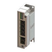
RCM-P6HUB
IAI RCM-P6HUB Manuals
Manuals and User Guides for IAI RCM-P6HUB. We have
2
IAI RCM-P6HUB manuals available for free PDF download: Instruction Manual, First Step Manual
IAI RCM-P6HUB Instruction Manual (286 pages)
Fieldbus Communication
Brand:
IAI
| Category:
Conference System
| Size: 11 MB
Table of Contents
Table of Contents
6
Safety Guide
13
Precautions in Operation
20
International Standards Compliances
23
Name for each Parts and Their Functions
24
Actuator Axes
30
Chapter 1 Specifications Check
33
Product Check
33
Parts
33
Teaching Tool
35
Instruction Manuals Related to this Product, Which Are Contained in the Instruction Manual (DVD)
36
How to Read the Model Nameplate
37
How to Read the Model
38
List of Basic Specifications
39
Specification of Built-In Controller
39
Specification of Gateway Unit
40
Specification of Hub Unit
40
Specification of RCP6S Gateway Controllers
41
Specification of Environment (Built-In Controller/Gateway Unit/Hub Unit/Rcp6S Gateway Controller in Common)
43
The Calculation of Number of Connectable Axes and Power Capacity
44
Specifications for each Fieldbus
45
Specifications of Devicenet Interface
45
Specifications of CC-Link Interface
45
Specifications of PROFIBUS-DP Interface
46
Specifications of Ethernet/Ip Interface
46
Specifications of Ethercat Interface
46
Specifications of PROFINET-IO Interface
47
External Dimensions
48
Gateway Unit
48
Hub Unit
49
RCP6S Gateway Controller
50
Installation and Storage Environment
51
Noise Elimination and Mounting Method
52
Chapter 2 Wiring
55
Wiring Diagram (Connection of Construction Devices)
57
Circuit Diagram
58
Wiring Method (Gateway Unit)
69
Wiring to Power Input Connector
69
Wiring Layout of System I/O Connector
71
Wiring of Drive-Source Cutoff Connector
72
Connection with the Actuator/Hub
73
Connection of Teaching Tool (SIO Connector, USB Connector)
74
Wiring of Fieldbus Connector
76
Wiring Method (Hub Unit)
81
Connection with the Gateway Unit
81
Connection with the Actuator
82
Brake Release Switch
82
Wiring Method (RCP6S Gateway Controllers)
83
Connection with the Gateway Unit/Hub Unit
83
Connection with the Actuator/ Connector Conversion Unit
84
Connection of Teaching Tool
85
Chapter 3 Operation
87
Basic Operation
87
Basic Operation Methods
87
Left-Justification Feature
90
Initial Setting
92
Operation Mode Setting (Setting in Gateway Parameter Setting Tool)
92
Parameter Settings (Setting on RC PC Software)
99
Setting of Position Data
100
Fieldbus Type Address Map
107
PLC Address Construction by each Operation Mode
107
Gateway Control Signals (Common for All Operation Modes)
109
Control Signals for Simple Direct Mode
112
Control Signals for Positioner 1 Mode
117
Control Signals for Direct Indication Mode
122
Control Signals for Positioner 2 Mode
129
Control Signals for Positioner 3 Mode
133
Control Signals for Positioner 5 Mode
136
Input and Output Signal Process for Fieldbus
140
Power Supply
141
Battery-Less Absolute
141
Incremental
142
Control and Functions of Input and Output Signals of Modes
143
Input and Output Signal Functions
143
Operation for Positioner 1/Simple Direct Modes
157
Operation for Direct Indication Mode
158
Operation for Positioner 2, Positioner 3 and Positioner 5 Modes
159
About Gateway Parameter Setting Tool
160
Startup of Tool
160
Explanation of each Menu
161
Description of Functions
163
Operation Mode Setting
170
Fieldbus I/O Domain Left-Justification Setting
171
Fieldbus Status Leds
172
Devicenet
172
CC-Link
173
Profibus-Dp
174
Ethernet/Ip
175
Ethercat
176
Profinet-Io
177
Chapter 4 Vibration Suppress Control Function
179
Setting Procedure
181
Settings of Parameters for Vibration Suppress Control
182
Setting of Position Data
183
Chapter 5 Collision Detection Feature
185
Collision Detection Judgement
185
Settings
186
Adjustment
186
Chapter 6 Power-Saving Function
187
Automatic Servo-Off and Full Servo Functions
187
Setting of Periods Taken until Automatic Servo off
188
Set of Power-Saving Mode
188
Status of Positioning Complete Signal in Selection of Automatic Servo off
189
Selecting Automatic Current Reduction Feature
190
Process When Feature Is Active
191
Caution
191
Chapter 7 Absolute Reset
193
Absolute Reset
193
Chapter 8 Parameter
197
Parameter List
198
Detail Explanation of Parameters
203
Servo Adjustment
236
Adjustment of Pulse Motor and Servo Motor
236
Adjustment of Brushless DC Electric Motor
238
Chapter 9 Troubleshooting
239
Action to be Taken Upon Occurrence of Problem
239
Fault Diagnosis
240
Impossible Operation of Controller
240
Positioning and Speed of Poor Precision (Incorrect Operation)
242
Generation of Noise And/Or Vibration
243
Impossible Communication
243
Gateway Alarm
244
Gateway Alarm Codes
244
Connection Unit Control Power Voltage Drop Alarm
246
Driver Alarm
247
Alarm Level
247
Simple Alarm Code
247
Alarm Codes for Driver Board
249
Chapter 10 Appendix
261
Conformity to Safety Category
261
When Connecting Power with Plus Grounding
275
Maintenance
276
Consumed Parts
276
Maintenance Information
276
List of Connectable Actuators
277
Chapter 11 Warranty
281
Warranty Period
281
Scope of the Warranty
281
Honoring the Warranty
281
Limited Liability
281
Conditions of Conformance with Applicable Standards/Regulations, Etc., and Applications
282
Other Items Excluded from Warranty
282
Change History
283
Advertisement
IAI RCM-P6HUB First Step Manual (5 pages)
Fieldbus Communication
Brand:
IAI
| Category:
Conference System
| Size: 2 MB
Table of Contents
1. Parts
1
2. Teaching Tool (Please Purchase Separately)
1
3. Instruction Manuals Related to this Product, Which Are Contained in the Instruction Manual (DVD).
1
4. How to Read the Model Plate
1
5. How to Read Controller Model Code
1
External Dimensions
2
Installation Environment
2
Installation and Noise Elimination
2
1. Noise Elimination Grounding (Frame Ground)
2
2. Precautions Regarding Wiring Method
2
3. Noise Sources and Elimination
2
4. Cooling Factors and Installation
2
Devicenet Interface
2
PROFIBUS-DP Interface
2
Ethernet/Ip Interface
2
Wiring Diagram
3
1. Connection to RCP6S Gateway Unit and Hub Unit
3
2. Connection to RCP6S Gateway Unit and RCP6S
3
3. Connection to RCP6S Hub Unit and RCP6S
3
Power Supply and Emergency Stop Circuit
3
Operation Mode Selected
3
Operation Modes
3
Connection Cable
3
Devicenet Type
4
CC-Link Type
4
PROFIBUS-DP Type
4
Ethernet/Ip Type
4
Ethercat Type
4
PROFINET-IO Type
4
Starting Procedures
5
Status Indicator LED
5
Installation and Wiring
5
Important Check Item
5
Power Supply and Alarm Check
5
Initial Setting
5
Servo on
5
Check of Safety Circuit
5
Setting of Position Data [Except for Direct Numerical Specification Mode]
5
Test Run Adjustment 1
5
Advertisement
Related Products
IAI RCM-P6GW
IAI RCM-P6PC
IAI RCM-P6AC
IAI RCM-P6DC
IAI RCP6S
IAI RCM-GW-CC
IAI RCM-GW-PR
IAI RCM-TD
IAI RCM-T
IAI RCP6-RRA7R-LCT
IAI Categories
Controller
Digital Camera
Gateway
Industrial Equipment
Security Camera
More IAI Manuals
Login
Sign In
OR
Sign in with Facebook
Sign in with Google
Upload manual
Upload from disk
Upload from URL