Sign In
Upload
Manuals
Brands
Hydronix Manuals
Measuring Instruments
HV04
User Manuals: Hydronix HV04 Moisture Display
Manuals and User Guides for Hydronix HV04 Moisture Display. We have
1
Hydronix HV04 Moisture Display manual available for free PDF download: User Manual
Hydronix HV04 User Manual (93 pages)
Brand:
Hydronix
| Category:
Measuring Instruments
| Size: 1 MB
Table of Contents
Table of Contents
7
Chapter 1 Introduction
15
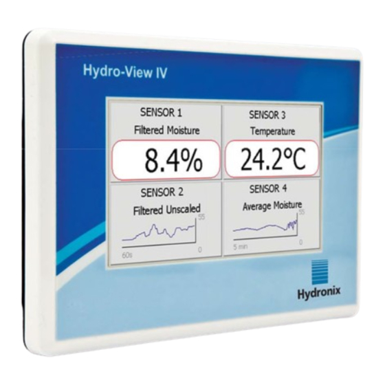
Introduction to the Hydro-View (HV04)
15
Figure 1: the Hydro-View
15
About this Manual
16
Safety
16
Application Examples
18
Chapter 2 Mechanical Installation
19
Weight and Dimensions
19
Figure 2: Rear View of the Hydro-View
19
Mounting and Installation
20
Figure 3: the Hydro-View Mounting Bracket
20
Figure 4: the Panel Cut-Out for the Hydro-View
20
Operating Temperature
21
Memory Card
21
Chapter 3 Electrical Installation
23
Connector Pin Assignments
23
Figure 5: Fitting the RS485 Adapter
23
Figure 6: Hydro-View Wiring Diagram
24
Figure 7: Hydro-View Wiring Diagram (with Hydronix Enclosure)
24
Power Supply
25
Communications
25
Figure 8: Hydronix Enclosure Internal Wiring
25
Cables
26
USB Port
27
Chapter 4 Configuration
29
Logging in as Engineer
29
Connecting Sensors
29
Configuring Sensors
29
Configuring the System Settings
29
Configuring the Overview Screen
30
Calibrating the Sensors
30
Upgrading the Hydro-View Firmware
30
Backing up the System
30
Chapter 5 System Navigation
31
Screen Navigation
31
Figure 9: Menu Structure
31
The Overview Screen
35
Figure 10: the Overview Screen
35
Figure 11: Sensor Quick View First Page
35
Figure 12: Sensor Quick View Second Page
36
Figure 13: Sensor Quick View Third Page
36
Main Menu Screen
37
Figure 14: the Main Menu Screen
37
User Accounts Screen
38
Figure 15: the User Accounts Screen
38
System Screens
39
Figure 16: the First System Screen
39
Figure 17: the Second System Screen
40
Figure 18: Overview Display Setup
40
Figure 19: Overview Screen Sensor Selector
40
Figure 20: Display Graph
40
Sensor Screens
41
Figure 21: the Third System Screen
41
Figure 22: Sensor Setup Screens
41
Figure 23: Sensor Identification Screen
42
Figure 24: Firmware/Event Log
42
Figure 25: Sensor Backup / Restore Screen
43
Figure 26: Analogue Output Screen 1
43
Figure 27: Analogue Outputs Screen 2
45
Figure 28: Digital Inputs / Outputs Screen
46
Figure 29: I/O Test Screen
47
Figure 30: Averaging Screen
48
Figure 31: Autotrack Configuration
49
Figure 32: Signal Processing Screen (1)
50
Figure 33: Signal Processing Screen (2)
50
Figure 34: Factory Settings Screen
51
Figure 35: Hydro-Probe Orbiter Arm Selection
52
Figure 36: Autocal in Progress
52
Figure 37: Temperature Compensation Screen
52
Figure 38: Calibration Screen
53
Figure 39: Temperature Screen
53
Figure 40: Sensor Status
54
Figure 41: Sensor Status
54
Figure 42: Resonator Screen
55
Calibration Screens
56
Figure 43: Calibration List Screen
56
Figure 44: Edit Calibration Screen
57
Figure 45: Edit Calibration Points Screen
59
Figure 46: Averaging Screen
59
Figure 47: Automatic Averaging
60
Figure 48: Automatic Averaging Started
60
Figure 49: Remote Averaging Stopped
60
Figure 50: Manual Averaging
61
Figure 51: Manual Averaging Started
61
Figure 52: Manual Averaging Stopped
61
Figure 53: Averaging Configuration
62
Figure 54: Edit Calibration Points Graph Screen
62
Logging Screens
63
Figure 55: Logging Screen
63
Figure 56: Logging Interval
63
Figure 57: Logging List
64
Figure 58: Sensor Logging Setup
64
Figure 59: Sensor Added to Logging List
65
Figure 60: Multiple Sensor Log
65
Figure 61: File Name
65
Figure 62: Sensor Logging Started
65
Figure 63: Processing Data Message
66
Chapter 6 Material Calibration
67
Calibrating a Sensor
67
Figure 64: Calibration Data Table
67
Figure 65: New Calibration
68
Figure 66: Edit Calibration Screen
69
Figure 67: Averaging
69
Figure 68: Mode Selection
69
Figure 69: Multiple Unscaled Values
69
Figure 70: Points Details Screen
69
Quick Start Rules
70
Figure 71: Moisture % Added to Chart
70
Figure 72: Expanded Calibration Graph
70
Figure 73: Calibration Coefficients
70
Figure 74: Quick Start Rules Selector
70
Calibration Procedure
71
Figure 75: Quick Start Rules Applied
71
Figure 76: Moisture Added to Data Table
76
Figure 77: Several Calibration Points
76
Figure 78: Selected Points
76
Figure 79: Calibration Graph
77
Figure 80: Write Calibration to the Sensor
77
Appendix A Default PIN Codes
79
Appendix B USB Memory Stick File Format
81
Appendix C Quick Start Rules
83
Quick Start Rules
83
Appendix D Frequently Asked Questions
85
Appendix E Diagnostics
87
Advertisement
Advertisement
Related Products
Hydronix Hydro-View HV02
Hydronix HD0538
Hydronix HD0333
Hydronix Hydro-Control VI
Hydronix Hydro-Hub
Hydronix Hydro-Probe SE
Hydronix Hydro-Probe
Hydronix Hydro-Probe XT
Hydronix Hydro-Probe Orbiter
Hydronix Hydro-Mix
Hydronix Categories
Accessories
Measuring Instruments
Adapter
Control Unit
Touchscreen
More Hydronix Manuals
Login
Sign In
OR
Sign in with Facebook
Sign in with Google
Upload manual
Upload from disk
Upload from URL