
Subscribe to Our Youtube Channel
Related Manuals for Hydronix HV04


Summary of Contents for Hydronix HV04
- Page 1 Hydro-View User Guide To re-order quote part number: HD0531 Revision: 2.0.0 Revision date: September 2016...
- Page 2 Neither the whole or any part of the information contained in nor the product described in this documentation may be adapted or reproduced in any material form except with the prior written approval of Hydronix Limited, hereinafter referred to as Hydronix.
- Page 3 Hydronix Offices UK Head Office Address: 7 Riverside Business Centre Walnut Tree Close Guildford Surrey GU1 4UG Tel: +44 1483 468900 Fax: +44 1483 468919 Email: support@hydronix.com sales@hydronix.com Website: www.hydronix.com North American Office Covers North and South America, US territories, Spain and Portugal...
- Page 4 Hydro-View User Guide HD0531 Rev 2.0.0...
- Page 5 Revision history Revision Software Date Description of Change Version 1.0.0 1.0.0 May 2012 First Release 1.1.0 1.1.0 June 2012 Diagnostics Section Updated 1.2.0 1.3.0 Jan 2013 Averaging Mode and Sensor Restore Updated. Calibration section Updated 1.2.1 1.3.0 May 2013 Minor Formatting update 1.3.0 1.3.0 Aug 2013...
- Page 6 Hydro-View User Guide HD0531 Rev 2.0.0...
-
Page 7: Table Of Contents
Table of Contents Chapter 1 Introduction ........................... 15 Introduction to the Hydro-View (HV04) ..................15 About this Manual ........................16 Safety ............................16 Application Examples ......................... 18 Chapter 2 Mechanical Installation ......................19 Weight and Dimensions ......................19 Mounting and Installation ......................20 Operating Temperature ...................... - Page 8 Appendix F Glossary ..........................89 Appendix G Document Cross Reference ....................91 Document Cross Reference ....................... 91 Hydro-View User Guide HD0531 Rev 2.0.0...
- Page 9 Figure 4: The Panel Cut-Out for the Hydro-View .................. 20 Figure 5: Fitting the RS485 Adapter ..................... 23 Figure 6: Hydro-View Wiring Diagram ....................24 Figure 7: Hydro-View Wiring Diagram (with Hydronix Enclosure) ............24 Figure 8: Hydronix Enclosure Internal Wiring ..................25 Figure 9: Menu Structure ........................31 Figure 10: The Overview Screen ......................
- Page 10 Figure 40: Sensor Status Page 1 ......................54 Figure 41: Sensor Status Page 2 ......................54 Figure 42: Resonator Screen ........................ 55 Figure 43: Calibration List Screen ......................56 Figure 44: Edit Calibration Screen ......................57 Figure 45: Edit Calibration Points Screen ..................... 59 Figure 46: Averaging Screen ........................
- Page 11 Figure 81: Sensor Calibration ....................... 77 Figure 82: USB Memory Stick File Layout .................... 81 Hydro-View User Guide HD0531 Rev 2.0.0 11...
- Page 12 Hydro-View User Guide HD0531 Rev 2.0.0...
- Page 13 Box Contents Standard Contents: Hydro-View Unit Mounting Bracket RS-485 and Power Adaptor Documentation CD Quick Installation Guide Quick Start Guide Available accessories: Part No. Description 0116 24v DC Power Supply 30 Watt 0175 Panel Mount USB Socket 2010 Wall Mounted Enclosure Hydro-View User Guide HD0531 Rev 2.0.0 13...
- Page 14 Hydro-View User Guide HD0531 Rev 2.0.0...
-
Page 15: Chapter 1 Introduction
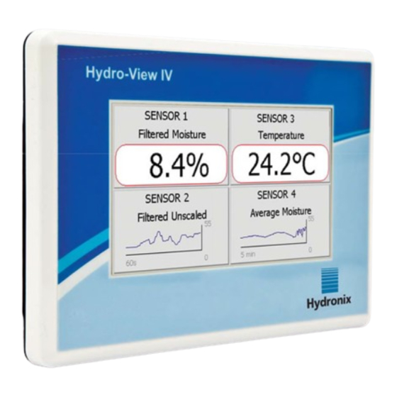
The Hydro-View is a touch screen computer based upon the Microsoft Windows CE operating system that has been designed to work with the Hydronix range of sensors to provide a live display of on-line process measurements and enable quick and easy calibration and configuration of the sensors. -
Page 16: About This Manual
Intended Purpose The Hydro-View is intended to be used as a display, calibration and configuration interface for Hydronix sensors in an industrial environment where it should be installed by suitably qualified and competent personnel. Precautions This unit is suitable for indoor use only. - Page 17 Chapter 1 Introduction Ensure that only fuses of the correct type and rating are fitted. Ensure that the Hydro-View is mounted in an environment that will not cause electrical interference. Explanation of Symbols and Markings It is important to understand the meaning of the various symbols and markings on the Hydro- View equipment as follows: Caution –...
-
Page 18: Application Examples
The Hydro-View may be used to configure and monitor Hydronix sensors in a variety of applications. It is possible to connect the Hydro-View to any of the current range of Hydronix digital sensors. The specific choice of sensor will depend upon the requirements of the application. -
Page 19: Chapter 2 Mechanical Installation
Chapter 2 Mechanical Installation Figure 2: Rear view of the Hydro-View 1 Weight and Dimensions Fascia: 145mm (W) x 104mm (H); (5.7” (W) x 4.1” (H)) Panel Cut Out: 128mm (W) x 94mm (H); (5.1” (W) x 3.7” (H)) Max Panel Thickness: Depth: 41mm (1.6”) Depth behind fascia:... -
Page 20: Mounting And Installation
Mechanical Installation Chapter 2 2 Mounting and Installation Panel Mounting The unit can be mounted in a control panel (maximum thickness 3mm) using the mounting bracket supplied. To fit the mounting bracket, locate the bracket holes over the four screws on the rear of the Hydro-View and drop into place. -
Page 21: Operating Temperature
Chapter 2 Mechanical Installation Mounting with Hydronix Enclosure If a suitable control panel or cabinet is not available, the Hydro-View may be mounted in the Hydro-View Wall Mounted Enclosure (part number 2010). The Hydro-View is fitted inside the enclosure as described in section 2.1. The cables supplied in the enclosure are connected to the Hydro-View and tightened in place with their locking screws. - Page 22 Mechanical Installation Chapter 2 Hydro-View User Guide HD0531 Rev 2.0.0...
-
Page 23: Chapter 3 Electrical Installation
Chapter 3 Electrical Installation This chapter explains the configuration of the connectors on the Hydro-View unit and how the wiring should be designed and installed. These connections will vary depending on the configuration and integration requirements of the system design. The supplied RS485 Adapter should be plugged into the 9-way D plug on the bottom of the unit, and secured in place with the fixing screws. -
Page 24: Figure 6: Hydro-View Wiring Diagram
MIL-SPEC connector) Figure 7: Hydro-View Wiring Diagram (with Hydronix Enclosure) Using a suitable cable gland, connect a cable into the Hydro-View enclosure and wire to the four way terminal block in the bottom right hand corner as shown in Figure 7. The wires from the top of the terminal block are then wired into the Hydro-View as shown in Figure 8. -
Page 25: Power Supply
View, a more appropriate, higher powered supply must be specified. 3 Communications RS485 The RS485 connection is used for communicating with Hydronix moisture sensors. It is possible to update the material calibration, change operating parameters and carry out sensor diagnostics from the Hydro-View. -
Page 26: Cables
Electrical Installation Chapter 3 Ideally, sensors on a RS485 network should be connected in a daisy chain arrangement, as shown here: In practice, this arrangement is hard to achieve, so sensors may be wired using very short stubs: Although it may appear simpler, wiring in a star configuration with each sensor wired back to the Hydro-View should be avoided. -
Page 27: Usb Port
This accepts a standard USB memory stick of up to 4GBytes. A panel mounting USB socket with an extension cable is available from Hydronix (Part Number 0175) to provide easier access to the USB socket. This has a 1.5m cable and the panel mounted socket needs a 28mm diameter hole with a 3mm key cut-out. - Page 28 Electrical Installation Chapter 3 Hydro-View User Guide HD0531 Rev 2.0.0...
-
Page 29: Chapter 4 Configuration
1 and 16. All new sensors shipped by Hydronix are set to address 16. For this reason it is recommended to connect sensors one at a time to the Hydro-View. When each sensor is connected its address should be changed, as described in Chapter 5 Section 6.1. -
Page 30: Configuring The Overview Screen
Detailed information regarding calibration and the calibration procedure is given in Chapter 6. 7 Upgrading the Hydro-View Firmware From time to time Hydronix will issue updates to the Hydro-View Firmware. These may add new features and functions to the product and are also designed to improve performance. -
Page 31: Chapter 5 System Navigation
Chapter 5 System Navigation 1 Screen Navigation The Hydro-View is a touch screen device. Navigation of the system is achieved by touching on the screen itself to activate relevant features. This must be done with a finger – tools such as pens and screwdrivers will not work and may damage the surface of the screen (unless supplied with the unit). - Page 32 Applying Power The Hydro-View starts up as soon as power is applied to it. The green light in the bottom right hand corner of the bezel will illuminate and the screen starts with a Hydronix start-up screen and progress indicator.
- Page 33 Chapter 5 System Navigation Press the current system language name Select the required language from the list Hydro-View User Guide HD0531 Rev 2.0.0 33...
- Page 34 System Navigation Chapter 5 Access Levels and Permissions The Hydro-View provides three User Access levels, each with different permissions. This allows the system to be ‘locked down’ for the majority of users, allowing only approved users to access the more in-depth system functionality. If one of the functions described here is not available to you, this is most likely because you are not logged in with sufficient permissions.
-
Page 35: The Overview Screen
Chapter 5 System Navigation 2 The Overview Screen The Overview Screen is the main screen used for displaying sensor information. Figure 10: The Overview Screen The Overview Screen may be configured to display 1, 2 or 4 ‘areas’ each of which may be configured separately. -
Page 36: Figure 12: Sensor Quick View Second Page
System Navigation Chapter 5 The second page displays the current Filtered Unscaled and Filtered Moisture Values. Averaging can also be started by pressing “Start Average” to display the Average Unscaled and Average Moisture values (Figure 12). If the connected sensor supports multi Measurement Modes the “Mode >” button can be pressed to display additional Measurement Mode values. -
Page 37: Main Menu Screen
Chapter 5 System Navigation 3 Main Menu Screen Operator Supervisor Engineer The Main Menu Screen accesses all other parts of the system. Different options will be enabled depending on the access level currently logged in. If no sensors have been found, then Sensor, Calibration and Logging will be disabled, regardless of the access level. -
Page 38: User Accounts Screen
Default PIN numbers are given in Appendix A. For added security, it is advisable to change these as soon as the system is commissioned. In the event that a PIN is changed and is subsequently forgotten, contact Hydronix Support for further assistance. Figure 15: The User Accounts Screen Current User shows which User is currently logged in. -
Page 39: System Screens
Chapter 5 System Navigation 5 System Screens There are three System Setup screens which allow the user to configure the user interface of the Hydro-View. Each screen requires different access permission levels. System Operator Supervisor Engineer Figure 16: The First System Screen Version The current firmware version of the Hydro-View. -
Page 40: Figure 17: The Second System Screen
System Navigation Chapter 5 Display Setup Operator Supervisor Engineer Figure 17: The Second System Screen 5.2.1 Display Setup Configuration Pressing the Display Setup button will open the Overview Screen setup (Figure 18). Figure 18: Overview Display Setup The Overview Screen can be configured to display 1, 2 or 4 sensor values. -
Page 41: Sensor Screens
Chapter 5 System Navigation Backup/Restore Operator Supervisor Engineer Figure 21: The Third System Screen Backup Backs up or “Saves” the System Settings and Calibrations to a USB memory stick. Only one System Backup can be stored on a memory stick, any previous backups will be overwritten. Restore Restores the System Settings and Calibrations from a USB memory stick. -
Page 42: Figure 23: Sensor Identification Screen
Figure 24: Firmware/Event Log Upgrade - Upgrade the Sensor firmware. The upgrade is carried out from a Hydro-Com compatible upgrade file (downloadable from www.hydronix.com). This file must be placed on a USB memory stick in a folder \HydroView_IV\FirmwareFiles\. The file can then be selected from a list. -
Page 43: Figure 25: Sensor Backup / Restore Screen
\HydroView_IV\BackUpFiles\. The file should then be selected from a list of possible files. Restoring a sensor will overwrite all of its settings. Backup to sensor memory- All Hydronix sensors utilising firmware HS0102 and above have the ability to store the sensor configuration settings to its internal memory. This... - Page 44 System Navigation Chapter 5 The Measurement Mode, if available, can also be selected (see the Calibration and Configuration Guide HD0679 for details on the different Measurement Modes). Output 1 Variable: (touch to select) Select which measurement is to be output on Current Loop 1. Raw Moisture This is scaled from the 'Raw Unscaled' variable using the A, B, C and SSD coefficients.
-
Page 45: Figure 27: Analogue Outputs Screen 2
Chapter 5 System Navigation AutoTrack Value This is the AutoTrack value calculated by the sensor. See the Calibration and Configuration Guide HD0679 for details on using this value. AutoTrack Deviation This is the deviation from the AutoTrack value. See the Calibration and Configuration Guide HD0679 for details. -
Page 46: Figure 28: Digital Inputs / Outputs Screen
System Navigation Chapter 5 Digital Inputs / Outputs The sensors have one digital input and one digital input / output. These may be configured for a number of different uses. Figure 28: Digital Inputs / Outputs Screen I/P 1 Use - The current use of Input 1 (Touch to change): Unused The digital input is ignored. -
Page 47: Figure 29: I/O Test Screen
Chapter 5 System Navigation Sensor OK This output will be active if: • The frequency reading is between the defined air and water calibration points +/-3% • The amplitude reading is between the defined air and water calibration points +/-3% •... -
Page 48: Figure 30: Averaging Screen
System Navigation Chapter 5 Digital In 1 - Light indicates the status of Digital Input 1. Red for active (24V applied); White for inactive. Digital I/O 2 - Light indicates the status of Digital Input / Output 2 when this is configured to be used as an input. -
Page 49: Figure 31: Autotrack Configuration
Selectable between Raw and Filtered. Note that this option is only available with selected sensors. Raw should be selected for most applications. Filtered is suitable for mixer applications where the signal is very noisy, Contact Hydronix for advice in this instance. 6.5.2 AutoTrack This section is used to configure the AutoTrack values (Figure 31). -
Page 50: Figure 32: Signal Processing Screen (1)
System Navigation Chapter 5 Signal Processing screen (1) Figure 32: Signal Processing Screen (1) Filtering Time This shows the current smoothing time applied to the signal. Touch to change. This is useful when there is a lot of noise or variation in the signal. The options are 0, 1, 2.5, 5, 7.5, 10 and Any seconds. -
Page 51: Figure 34: Factory Settings Screen
Chapter 5 System Navigation Unscaled 2 (only shown for selected sensors) For sensors which support this option, this shows the current Measurement Mode used to calculate the Unscaled 2 reading. Touch to change. For further details of the Measurement Modes, refer to the Calibration and Configuration Guide HD0679. Material Temperature Alarm Low/High The Material High and Low Limits are used to configure the Material Temperature alarm. -
Page 52: Figure 35: Hydro-Probe Orbiter Arm Selection
6.6.2 Temperature Compensation Screen These settings should not be changed unless advised to do so by a Hydronix trained engineer. Figure 37: Temperature Compensation Screen Hydro-View User Guide HD0531 Rev 2.0.0... -
Page 53: Figure 38: Calibration Screen
Chapter 5 System Navigation Hydronix sensors include temperature compensation algorithms to provide a consistent reading over a wide temperature range. These coefficients are used to carry out the calculations and are set in the factory, individually to each sensor. These should not normally be changed. -
Page 54: Figure 40: Sensor Status
System Navigation Chapter 5 Electronics / Resonator / Material These show the current temperatures being measured by the sensor. Depending on the sensor type not all measurements may be available. These may be higher than the current air temperature due to internal heating of the electronics. Max / Min These show the maximum and minimum temperatures experienced by the internal electronics. -
Page 55: Figure 42: Resonator Screen
The run time indicates the amount of time the sensor has been powered up. 6.7.4 Resonator This screen contains advanced sensor diagnostic information that may be of use to Hydronix support personnel. Figure 42: Resonator Screen Graph This shows the live resonator response from the sensor. -
Page 56: Calibration Screens
System Navigation Chapter 5 7 Calibration Screens Operator Supervisor Engineer Full details of the Material Calibration process are given in Chapter 6. This section explains the navigation through the screens. When the Calibration button on the Main Menu is touched, a list of the connected sensors appears (if more than one is connected). -
Page 57: Figure 44: Edit Calibration Screen
Chapter 5 System Navigation Save to File Saves all of the Calibrations in the Hydro-View to a text file on a USB Memory stick. Write to Sensor Writes the coefficients for the currently selected Calibration to the sensor. Menu Returns to the Main Menu. Edit Calibration Screen Figure 44: Edit Calibration Screen Name... - Page 58 System Navigation Chapter 5 Quick Start Rules Shows the Quick Start rule selected for the Calibration. Selecting the correct rules for the application material can assist with creating an accurate Calibration, particularly if only a limited number of sample points are available. The options available are: •...
-
Page 59: Figure 45: Edit Calibration Points Screen
Chapter 5 System Navigation Edit Points Screen Figure 45: Edit Calibration Points Screen The main screen Displays a list of the points currently used in the Calibration. Touch either the Unscaled or Moisture box to edit the value. Touch the Include tick box to include / exclude the point from the calculation of the coefficients. -
Page 60: Figure 47: Automatic Averaging
System Navigation Chapter 5 7.4.1 Digital Input Set for Average / Hold (typical Batch Average application) With the Digital Input set for Average / Hold the Averaging Screen will open with the averaging mode set to Automatic (Figure 47). Figure 47: Automatic Averaging This carries out the Averaging function when the Average / Hold input is switched to active (Figure 48). -
Page 61: Figure 50: Manual Averaging
Chapter 5 System Navigation Figure 50: Manual Averaging Touch Start when the sample collection starts and touch Stop when collection ceases (Figure 51). Figure 51: Manual Averaging Started When averaging completes, a message is displayed giving the option of adding a new point to the Calibration (Figure 52). -
Page 62: Figure 53: Averaging Configuration
System Navigation Chapter 5 Figure 53: Averaging Configuration Edit Points Graph Screen Figure 54: Edit Calibration Points Graph Screen The ‘best fit’ line calculated from the currently included data points. The Calibration limit lines are shown in red if Quick Start Rules are enabled. A point that is further from the ‘best fit’... -
Page 63: Logging Screens
Chapter 5 System Navigation 8 Logging Screens Operator Supervisor Engineer The logging function enables the recording of sensor readings over a period of time. This may be useful for commissioning and optimising a system, including choosing the correct filter settings for the sensor. -
Page 64: Figure 57: Logging List
System Navigation Chapter 5 Select “New” to create a logging list (Figure 57) Figure 57: Logging List Touching the blue box enables the selection the sensor and variable is to be logged (Figure 58). Figure 58: Sensor Logging Setup Sensor Name If more than one sensor is connected to the Hydro-View a list will appear when the Sensor Name box is pressed. -
Page 65: Figure 59: Sensor Added To Logging List
Chapter 5 System Navigation Once the logging details have been entered the sensor will be added to the list (Figure 59). Figure 59: Sensor Added to Logging List Additional sensors values can be added to the list as required (Figure 60). Figure 60: Multiple Sensor Log Due to the available communications ‘bandwidth’, it may not be possible to log with all of the available options simultaneously. -
Page 66: Figure 63: Processing Data Message
System Navigation Chapter 5 Ensure that the following message is not displayed before removing the USB memory stick (Figure 63). Figure 63: Processing Data Message Hydro-View User Guide HD0531 Rev 2.0.0... -
Page 67: Chapter 6 Material Calibration
Measurement Mode used to calculate the Unscaled output. To output moisture using the different Measurement Modes requires separate coefficients for each mode (F, E and V). In older Hydronix sensors (Pre Firmware HS0102) the sensor has to be calibrated separately in each Measurement Mode to create the coefficients. -
Page 68: Figure 65: New Calibration
‘Raw’. See the Hydronix Sensor Configuration and Calibration Guide HD0679 or the appropriate sensor user guide for more details on how to set the averaging functionality for specific applications. -
Page 69: Figure 66: Edit Calibration Screen
Chapter 6 Material Calibration Recording the Average Unscaled To record an Average Unscaled value, select Averaging on the Edit Calibration page (Figure 66). Figure 66: Edit Calibration Screen The averaging can be started automatically or manually, depending on the current sensor set- up. -
Page 70: Quick Start Rules
Material Calibration Chapter 6 The required moisture and Unscaled values can be added to the calibration by clicking the include column for each point (Figure 71). Figure 71: Moisture % Added to Chart Click “Graph” to display the calibration graph (Figure 72). Figure 72: Expanded Calibration Graph The graph can be configured to display any, or all, of the available Measurement Modes and best fit lines for the calibration as well as the current calibration stored in the sensor (grey line,... -
Page 71: Calibration Procedure
Chapter 6 Material Calibration The calibration data points define a mathematical best fit line and it is this line, described using the variables A, B and C, which defines the calibration. The effect of the Quick Start Rules is to improve this calibration line if the calibration data does not satisfy the criteria as described in Appendix C. - Page 72 Material Calibration Chapter 6 Handling Collected Material Samples To create an accurate calibration it is necessary to collect samples of the material as it passes over the sensor and, at the same time, record the Average Unscaled value from the sensor during the material collection period.
- Page 73 Chapter 6 Material Calibration Select “Averaging” to open the Averaging section. If automatic averaging using the bin gate signal is in use confirm that ‘Averaging’ is displayed on the calibration page when the bin gate opens. When the gate is closed confirm that the “Averaging is Compete” pop up window is displayed.
- Page 74 Material Calibration Chapter 6 10. Once the sensor Averaging is complete add the values to the chart. 11. The Average Unscaled for each available Measurement Mode is displayed on the Calibration Screen. Select the “Mode>” button to display each of the Measurement Mode data points. 12.
- Page 75 Chapter 6 Material Calibration material to be burnt off. Check industry standards for the maximum temperature suitable for the material. 18. Carefully break up any lumps of material using a metal spoon. Do not allow any material to be lost from the bowl or to stick to the spoon. Only break up lumps once the material surface is dry.
-
Page 76: Figure 76: Moisture Added To Data Table
28. It is now possible to evaluate the points included and to inspect the best fit line that has been generated. The output from Hydronix moisture sensors is linear to moisture change so accurately collected and analysed samples should be on or very close to the best fit line. -
Page 77: Figure 79: Calibration Graph
Chapter 6 Material Calibration Figure 79: Calibration Graph See the Calibration and Configuration Guide HD0679 for details about the Measurement Modes. 29. Once a calibration has been completed successfully the data can be written to the sensor. All available Measurement Mode coefficients will be updated and if the sensor supports the facility the calibration points (Unscaled and Moisture %) will also be transferred to the sensor. - Page 78 Material Calibration Chapter 6 Hydro-View User Guide HD0531 Rev 2.0.0...
-
Page 79: Appendix A Default Pin Codes
Appendix A Default PIN Codes When the Hydro-View is first powered up, the following PIN codes are set as standard: User Level Default PIN Code Supervisor 3737 Engineer 0336 It is recommended that these are changed once the system is commissioned to prevent inadvertent access to the system and settings. - Page 80 Default PIN Codes Appendix A Hydro-View User Guide HD0531 Rev 2.0.0...
-
Page 81: Appendix B Usb Memory Stick File Format
Must be created by Upgrade folder. Hydro-View Backup User if needed. Files Database file. Upgrades to HV04 firmware are placed elsewhere placed in this folder, in unzipped Created when System is the disk will not be format. At power up, this folder is... - Page 82 USB Memory Stick file format Appendix B Hydro-View User Guide HD0531 Rev 2.0.0...
-
Page 83: Appendix C Quick Start Rules
Appendix C Quick Start Rules 1 Quick Start Rules • Limiting slopes (B) for any calibration will be a maximum of 2.0 and a minimum of 0.06. • One-point calibrations: • The calibration slope will be set to be the average of the two known sand calibrations. •... - Page 84 Quick Start Rules Appendix C Hydro-View User Guide HD0531 Rev 2.0.0...
-
Page 85: Appendix D Frequently Asked Questions
Can I adjust the contrast on the display? There is no way of adjusting the contrast of the display on a Hydro-View. If either the backlight or the contrast is faulty, then the unit will need to be repaired by Hydronix. _ _ _ We had a lightning strike and now the unit doesn’t work properly, can I do any onsite repairs? - Page 86 Frequently Asked Questions Appendix D Hydro-View User Guide HD0531 Rev 2.0.0...
-
Page 87: Appendix E Diagnostics
Diagnostics The following tables list the most common faults found when using the Hydro-View. If you are unable to diagnose the problem from this information, please contact your system installer or Hydronix reseller. Symptom: Displays shows ‘Searching For Sensor’ - no output from sensor... - Page 88 Required result Action required on failure Incorrectly configured Display Display Contact your system installer Display Area Setup screen Configuration or Hydronix reseller for more Overview screen verify that corrected details. correct sensor and variable is selected – especially sensors have not...
- Page 89 Automatic Calibration (AutoCal) To simplify repeating the factory calibration, some Hydronix sensors can be automatically calibrated. This sets the air and water values for the sensor or connected sensing arm. The sensor face must be clean, dry and obstruction free to run the automatic calibration. Note that the result of this AutoCal is not as precise as carrying out a full Air and Water calibration.
- Page 90 Glossary Appendix F SD card See Micro/Mini SD card Sensor The sensor is the physical device that is used to measure moisture in materials. The sensor consists of a stainless steel case containing the electronic components connected to a resonator which sits behind a ceramic faceplate.
- Page 91 Appendix G Document Cross Reference 1 Document Cross Reference This section lists all of the other documents that are referred to in this User Guide. You may find it beneficial to have a copy available when reading to this guide. Document Number Title HD0679...
- Page 92 Document Cross Reference Appendix G Hydro-View User Guide HD0531 Rev 2.0.0...
- Page 93 Index Analogue output ..........43 Frames AutoTrack ............47 Analogue Output ........43 Average/Hold Installation ............. 20 Delay ............48 Mechanical Installation Averaging Mounting ........... 20 Automatic ..........68 Mixing Applications ........18 Averaging Mode ........68 Operating Temperature......... 21 Remote ............
Need help?
Do you have a question about the HV04 and is the answer not in the manual?
Questions and answers