Sign In
Upload
Manuals
Brands
HydraMaster Manuals
Test Equipment
Boxxer 423s
HydraMaster Boxxer 423s Manuals
Manuals and User Guides for HydraMaster Boxxer 423s. We have
1
HydraMaster Boxxer 423s manual available for free PDF download: Owner's Manual
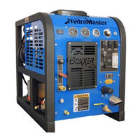
HydraMaster Boxxer 423s Owner's Manual (92 pages)
Brand:
HydraMaster
| Category:
Test Equipment
| Size: 7 MB
Table of Contents
Table of Contents
2
General Information
6
Major System Components
7
Contact Information
8
Warnings, Cautions and Notices
8
Responsibilities
10
Machine Specifications
12
High Altitude Operation
13
Local Water Precautions
13
Figure 1-1. Hard Water Map of Mainland United States
13
Installation Information
16
Operating the Boxxer 423S in Hot Weather
17
Figure 2-2. Recommended Location of Boxxer 423S in Van
17
Setting up the Boxxer 423S
18
Orientation of Fuel Pump
19
Figure 2-3. Install Fuel Pump, Outlet Side up
19
Figure 2-4. Fuel Pump Must be in Vertical Position
19
Cleaning and Chemicals
20
Precautions
20
Overwetting
21
Preparing the Carpet for Extraction
21
Rinse and Recover
21
Streaking
21
Cleaning Tool Tips
22
Figure 4-1. Boxxer 423S Upper Dash Assembly
26
Figure 4-2. Boxxer 423S Lower Dash Assembly
27
Start up Procedure
27
Figure 4-3. Boxxer 423S Chemical System Control and Metering
28
Shut down Procedure
28
Operating Instructions
26
Machine Maintenance
30
Operational Maintenance
31
Overall Machine Maintenance
32
Engine Maintenance
32
High Pressure Pump Maintenance
33
Figure 5-1. Remove Valve Cap and Valve Assembly
34
Figure 5-2. Inspect Manifold and Old Valves
34
Figure 5-3. Replace Center Inlet Check Valve with Modified Check Valve
34
Figure 5-4. Apply Grease and Install Valves
34
Figure 5-5. Replace Valve Capand Torque to 95 Ft Lbs
34
Figure 5-6. Separate Manifold from Crankcase
35
Figure 5-7. Seal Assemblies May Come off with Manifold
35
Figure 5-8. Examine Ceramic Plungers
35
Figure 5-9. Remove Stainless Steel Plunger Bolt and Ceramic Plunger
35
Figure 5-10. Install O-Ring, Apply Sealant and Slide Plunger over Plunger Guide
35
Figure 5-11. Extract Retainers and Seals
36
Figure 5-12. Seal Kit and Insertion Tool for Seal Installation
36
Figure 5-13. Install Seal Assembly Using O-Ring Grease
36
Figure 5-14. Install Retainers into Cavities
37
Figure 5-15. Press Low Pressure Seal Assembly into Cavity
37
Figure 5-16. Re-Install Manifold and Torque Fasteners
37
Vacuum System Maintenance
38
Descaling Procedure (Required)
38
Figure 5-19. Recirculation Fitting
38
Freeze Guarding
39
Water and Chemical System
41
Figure 6-1. Flow Diagram - View 1 of 3
43
Electrical System
46
Electrical System Information
46
Systems Troubleshooting
50
Heating System
51
Chemical System
51
Engine
52
High Pressure System
54
Vacuum System
55
Assemblies and Parts Lists
57
Figure 9-1. Adhesive/Sealant Material Reference
58
Console Assembly Parts List
61
Figure 9-7. Console Assembly - View 6 of 6
61
Console Assembly Parts List (Continued)
62
Figure 9-8. Frame Assembly - View 1 of 2
62
Figure 9-10. Blower Assembly - View 1 of 2
63
Figure 9-9. Frame Assembly - View 2 of 2
63
Frame Assembly Parts List
63
Blower Assembly Parts List
64
Figure 9-11. Blower Assembly - View 2 of 2
64
Figure 9-12. Pump Assembly
65
Dash Assembly Parts List
67
Differential Check Valve Assembly Parts List
67
Figure 9-15. Differential Check Valve Assembly
67
By-Pass Valve Assembly Parts List
68
Figure 9-16. By-Pass Valve Assembly
68
Figure 9-17. Hi-PSI Manifold Assembly
69
Hi-PSI Manifold Assembly Parts List
69
Electrical Panel Assembly Parts List
70
Engine Assembly Parts List
71
Blower Heat Exchanger Assembly Parts List
72
Figure 9-22. Blower Heat Exchanger Assembly
72
Figure 9-23. Idler Pulley Assembly
73
Idler Pulley Assembly Parts List
73
Silencer Assembly Parts List
73
Figure 9-25. Water Box Assembly
74
Water Box Assembly Parts List
74
Exhaust Assembly Parts List
75
Exhaust Manifold Assembly Parts List
75
Figure 9-26. Exhaust Assembly
75
Figure 9-27. Exhaust Manifold Assembly
75
Exhaust Diverted Assembly Parts List
76
Figure 9-28. Exhaust Diverted Assembly
76
Diverter Valve Actuator Assembly Parts List
77
Figure 9-29. Diverter Valve Actuator Assembly
77
Figure 9-30. Exhaust Diverter Valve Assembly
77
Exhaust Diverter Valve Assembly Parts List
78
Figure 9-31. 70 Gallon Universal Recovery Tank (URT) Assembly
78
Figure 9-32. 70 Gallon Universal Recovery Tank (URT) Cover Assembly
79
Gallon Universal Recovery Tank (URT) Assembly Parts List
79
Figure 9-33. 100 Gallon Universal Recovery Tank (URT) Assembly
80
Gallon Universal Recovery Tank (URT) Cover Assembly Parts List
80
Figure 9-34. 100 Gallon Universal Recovery Tank (URT) Cover Assembly
81
Gallon Universal Recovery Tank (URT) Assembly Parts List
81
Figure 9-35. Vacuum Relief Valve Assembly
82
Gallon Universal Recovery Tank (URT) Cover Assembly Parts List
82
Vacuum Relief Valve Assembly Parts List
82
Figure 9-36. Dura-Flow APO Assembly
83
APO Pump Assembly Parts List
84
Figure 9-37. APO Pump Assembly
84
Hose Routings
84
How to Order Parts
86
Warranty Parts Orders
86
Parts Orders
86
Emergencies
86
Warranty Information
88
Blower
88
High Pressure Water Pump
88
Recovery Tank
88
Chemical System
88
Control Panel
88
Vacuum and Solution Hoses
89
Cleaning Wand and Tool
89
Water Heating System
89
Hard Water Deposits
89
Warranty Procedure
89
Accessories and Chemical Solutions
91
Advertisement
Advertisement
Related Products
HydraMaster Boxxer 427
HydraMaster CrossFire 4.2
HydraMaster Boxxer 421
HydraMaster MAXX 450D
HydraMaster MAXX 470D
HydraMaster Clutch Drive System 4.8 SV
HydraMaster Boxxer 318HP
HydraMaster BoxxerXL
HydraMaster Boxxer H2O
HydraMaster Boxxer 318
HydraMaster Categories
Vacuum Cleaner
Cleaning Equipment
Floor Machine
Water System
Scrubber
More HydraMaster Manuals
Login
Sign In
OR
Sign in with Facebook
Sign in with Google
Upload manual
Upload from disk
Upload from URL