Table of Contents
Advertisement
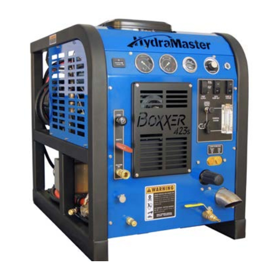
Boxxer 423s
Owner's Manual
HydraMaster
th
11015 47
Avenue West
Mukilteo, Washington 98275
MAN-45429 Rev. C, July 1, 2015
(P/N 000-182-728)
No part of this manual may be reproduced or used in any form or by any means (i.e. graphic, electronic, photocopying or electronic
retrieval systems) without the express written permission of HydraMaster. Specifications and information in this document are
subject to change without prior notice. All rights reserved. © 2015 HydraMaster
Advertisement
Table of Contents

Summary of Contents for HydraMaster Boxxer 423s
- Page 1 No part of this manual may be reproduced or used in any form or by any means (i.e. graphic, electronic, photocopying or electronic retrieval systems) without the express written permission of HydraMaster. Specifications and information in this document are subject to change without prior notice. All rights reserved. © 2015 HydraMaster...
-
Page 2: Table Of Contents
High Altitude Operation ................1-14 Local Water Precautions ................. 1-14 INSTALLATION INFORMATION ..............SECTION 2 Operating the Boxxer 423s in Hot Weather ..........2-2 Setting Up the Boxxer 423s ..............2-5 Orientation of Fuel Pump ................ 2-6 CLEANING AND CHEMICALS ..............SECTION 3 Precautions ..................... - Page 3 APO Pump Assembly Parts List .............. 9-54 Hose Routings..................9-55 HOW TO ORDER PARTS ................SECTION 10 Warranty Parts Orders ................10-1 Parts Orders .................... 10-1 Emergencies ................... 10-1 Boxxer 423S Owner’s Manual - ii iii - Boxxer 423S Owner’s Manual...
- Page 4 Figure 2-1. Location of Roof Vents in Vehicle ..............2-1 Figure 9-7. Console Assembly - View 6 of 6 ..............9-8 Figure 2-2. Recommended Location of Boxxer 423s in Van ........2-3 Figure 9-8. Frame Assembly - View 1 of 2 ..............9-11 Figure 2-3. Install Fuel Pump, Outlet Side Up ..............2-6 Figure 9-9.
- Page 5 Boxxer 423S Owner’s Manual - vi...
-
Page 6: General Information
HydraMaster, featuring a 23 HP air-cooled engine and the dual oil bath Tuthill Dominator 4005 Tri-lobe Blower. Available options for the Boxxer 423s include a 70 gallon recovery tank, a 5 gallon chemical jug, 100 ft vacuum and solution hoses, and a 10 ft whip hose. -
Page 7: Major System Components
It is the purpose of this manual to help you properly understand, maintain and service your Boxxer 423s. Follow the directions carefully and you will be rewarded with years of profitable, trouble-free operation. -
Page 8: Contact Information
If you have any questions regarding the operation, maintenance or repair of this machine, please contact your local distributor. To find a local distributor, please visit our website at HydraMaster uses this WARNING symbol throughout the manual to warn of possible injury or death. http://hydramaster.com/HowToBuy/DealerLocator.aspx If your question cannot be resolved by your distributor or by the information within this manual, you may contact HydraMaster direct using the following phone numbers. - Page 9 Scale build up causes serious in the past, a flammable liquid is strictly forbidden by HydraMaster and by federal component damage. Test all water prior to use and use water softening equipment and state regulations.
-
Page 10: Responsibilities
RESPONSIBILITIES Never allow water to freeze inside the truckmount. Serious component damage Purchaser’s Responsibilities will occur. Perform all freeze guarding procedures outlined in this digital Owner’s • Prior to purchasing a van, ensure that the payload is suitable for all of the equipment Manual. - Page 11 • Ensure proper connection of the fuel lines. • Ensure proper connection and installation of the battery. Verify that the battery is in accordance with HydraMaster’s recommendation. • Check the pump, vacuum blower and engine oil levels prior to starting the truckmount.
-
Page 12: Machine Specifications
MACHINE SPECIFICATIONS Standard Equipment Runtime Hour Meter Chemical Flow Meter (0-10 Frame Dimensions 24”W x 31”H x 36”D Gph) Weight 563 lbs Chemical Flow Control Valve Engine 23HP Briggs and Stratton air- Vacuum Gauge (0-30" Hg) cooled Solution Pressure Gauge Pressurized Oil System Engine Oil: (0 - 1,500 Psi) -
Page 13: High Altitude Operation
Hard Water Advisory HydraMaster recognizes that any hard water deposits which might occur within the water system of our truckmounts is a serious problem. The precision technology of truckmount heat exchanger systems is intolerant of any foreign material. Hard water deposits will ultimately decrease the performance of the system and are expected to seriously lower Figure 1-1. - Page 14 HydraMaster strongly urges the use of water softener units with the Boxxer 423s in areas exceeding 3.0 grains per gallon.
- Page 15 General Information: 1-18...
-
Page 16: Installation Information
Although there are many different heavy duty vehicles used for carpet cleaning equipment, the preferable vehicle for a Boxxer 423s installation is a cargo van with a heavy-duty suspension package and a 3/4 HD ton capacity. If a fresh water tank is added, a one ton or larger capacity van is required. -
Page 17: Operating The Boxxer 423S In Hot Weather
Figure 2-2. Recommended Location of Boxxer 423s in Van Secure Installation No matter how the unit is installed, check to see if the Boxxer 423s is properly secured to the floor of the van with the hardware provided. This safety measure will ensure that the machine will not slide inside the van. -
Page 18: Setting Up The Boxxer 423S
The Boxxer 423s is shipped from the factory with antifreeze added to the solution system. job site. Always park the truck so the exhaust is blowing away from the job site. -
Page 19: Orientation Of Fuel Pump
ORIENTATION OF FUEL PUMP For proper fuel pump operation and fuel flow, the vehicle’s fuel pump must be installed in a lower position with respect to the fuel tank and in as vertical a position as possible (outlet side up - see Figure 2-3 and Figure 2-4). -
Page 20: Cleaning And Chemicals
HydraMaster’s ClearWater Rinse™ has been formulated to protect vital components. HydraMaster will not warranty parts that have been damaged from using acid products that have obviously caused failures. 3-1: Cleaning Information... -
Page 21: Preparing The Carpet For Extraction
Streaks in the carpet can appear in both clean or dirty areas and normally appear in heavily soiled, light colored carpets. HydraMaster recommends the use of our pre-sprays: Fastbreak™ for residential carpet and Blitz™ for commercial carpet needs. Possible reasons of streaking may include: Clogged or improperly angled spray nozzles. -
Page 22: Cleaning Tool Tips
CLEANING TOOL TIPS Wands With a wand, keep cleaning strokes short, front to back, and run a “dry pass”. After pulling the wand for a strip of 3 or 4 ft long with the solution trigger activated, go back up to the top of the stroke, and make a “dry “ pass [i.e. no solution flowing]. This gives the wand a second chance to pick up the solution on the carpet. - Page 23 Rotary Tools HydraMaster’s selection of Rotary Extraction Tools includes ® the RX-15H and the RX-20 RX-15H Hard Surface Cleaning Tool The RX-15H can be used to clean tile, concrete and stone floors. Select the appropriate pre-spray and apply to the floor.
- Page 24 RX-20 Tool for Carpet, Hard Surface and Bonnet Cleaning Upholstery Tool - DriMaster 3 Before turning on the RX-20, adjust the handle; it should rest right below or even with the Use the upholstery tool on small rugs and furniture. When you clean rugs, be sure that the bottom of your pants’...
- Page 25 Cleaning Information: 3-10...
-
Page 26: Operating Instructions
4 - Operating Instructions This section describes how to operate the Boxxer 423s, starting with a description of the dash assembly (see Figure 4-1). Temperature Pressure Control Dial Vacuum Gauge Temperature Gauge Gauge Hour Ignition Switch Meter Auto Pump-Out Switch... -
Page 27: Start Up Procedure
Blower Lube Port Incoming Never clean when the Boxxer 423s is in the IDLE mode. Failure to follow this Fresh Water caution may result in serious component or engine damage. Pull the “THROTTLE” cable all the way out and lock into place. -
Page 28: Shut Down Procedure
Uncap the inlet(s) and run the unit for another minute to allow the blower to cool down. Figure 4-3. Boxxer 423s Chemical System Control and Metering If freeze guarding is necessary, perform the procedure at this time. See the Freeze Guarding section of this Owner’s Manual (see page 5-18). - Page 29 Operating Instructions: 4-6...
-
Page 30: Machine Maintenance
A maintenance log, provided in the Owner’s Guide, must be correctly and completely filled out. HydraMaster may request to inspect the logs before a warranty claim is honored. It is recommended that the log be affixed to the vehicle door near the truckmount for convenience and to serve as a maintenance reminder. -
Page 31: Operational Maintenance
• Check the fuel lines every 250 hours. Repair or replace as needed. • Lubricate the blower lube port with a HydraMaster-recommended lubricant, • Check valve clearance, intake and exhaust 0.004 to 0.006” every 250 hours. P/N 000-087-006. -
Page 32: Overall Machine Maintenance
Use only engine oils displaying the American Petroleum Institute (API) “starburst” certification mark ‘FOR GASOLINE ENGINES’ on the container. Engine Oil Recommendation While multi-viscosity oils are generally recommended, SAE 5W-30 synthetic is specifically recommended year round for your Boxxer 423s engine. Machine Maintenance: 5-4 5-5: Machine Maintenance... -
Page 33: High Pressure Pump Maintenance
HIGH PRESSURE PUMP MAINTENANCE Oil Filter Briggs and Stratton engines use Briggs and Stratton oil filters. An equivalent or better oil Daily filter must be used when servicing the engine. Check the oil level and the condition of the oil. The oil level should be up to the center of the sight glass on the side or rear of the pump or between the “MIN”... -
Page 34: Figure 5-1. Remove Valve Cap And Valve Assembly
Replace center inlet check valve with modified check valve Servicing Valves on the High Pressure Pump - Figure 5-3. Removing a Valve Remove the valve cap (30 mm) and extract the valve assembly (see Figure 5-1). Modified Check Valve Figure 5-1. Remove Valve Cap and Valve Assembly Figure 5-3. -
Page 35: Figure 5-6. Separate Manifold From Crankcase
10. Remove the fasteners retaining the manifold 15. Remove the stainless steel plunger bolt and ceramic plunger from the plunger guide Separate manifold from crankcase (see Figure 5-6). (see Figure 5-9). 16. If the slinger washer is removed, be certain it is re-installed or replaced. 17. -
Page 36: Figure 5-11. Extract Retainers And Seals
Extracting Seals Replacing the Seal Assemblies With manifold removed from crankcase: Only one seal kit is necessary to repair all the seals in the pump (see Figure 5-12). Use an insertion tool for seal installation Insert proper extractor collet through main seal retainer (see Figure 5-11). Tighten collet and extract retainers and seals. -
Page 37: Figure 5-14. Install Retainers Into Cavities
Re-Installing Manifold To install the intermediate retainers and the low pressure seals: Position the outer plungers at the same position (see Figure 5-16). Insert the brass intermediate retainer into the cavity. Re-install manifold and torque the fasteners in an “X” pattern to 50% of specification Press the new low pressure seal into the brass low pressure seal retainer and install and then retorque to 100% specification (see Figure 5-17 and Figure 5-18). -
Page 38: Vacuum System Maintenance
“OFF.” to remove moisture from the blower. Cap off the inlet(s) to the vacuum tank. Spray a HydraMaster-recommended spray lubricant into the “BLOWER LUBE PORT” for about 5 to 7 seconds while the unit is running. 000-078-058 Uncap the inlet(s) and run the unit for another minute to allow the blower to cool down. -
Page 39: Freeze Guarding
FREEZE GUARDING Freeze Guard Procedure To avoid permanent damage to the truckmount, it is imperative to follow the Freeze Guard With the truckmount turned off and the incoming water line disconnected, open Procedure whenever the possibility of freezing temperatures exists. the water box drain valve on the front of the truckmount. - Page 40 To freeze guard the hoses and wand, perform the preceding procedure with the items to be freeze guarded attached. Always check the freezing level of your reclaimed antifreeze with a glycol tester before reusing. Failure to do so may result in serious component damage. Recovering Antifreeze for Re-Use Attach all hoses and wands which have been freeze guarded to the truckmount.
-
Page 41: Water And Chemical System
6 - Water and Chemical System This section describes the Boxxer 423s’ water and chemical systems, and includes the exhaust subsystem. The process starts when fresh water is brought through the front of the truckmount into the water box, as indicated in Figure 6-1. The level of water in the box is maintained by the use of a float valve. - Page 42 Finally, the water joins the chemical where the solution is created (see Figure 6-2). The chemical is pressurized by the HydraMaster diaphragm chemical pump attached to the head of the water pump. This pump pulls the chemical from the chemical, or soap, jug through the chemical flow meter (see Figure 6-3).
-
Page 43: Figure 6-1. Flow Diagram - View 1 Of 3
Figure 6-1. Flow Diagram - View 1 of 3 000-179-045 Rev. A 6-3: Water and Chemical System... - Page 44 Figure 6-2. Flow Diagram - View 2 of 3 Figure 6-3. Flow Diagram - View 3 of 3 000-179-045 Rev. A 000-179-045 Rev. A Water and Chemical System: 6-4 6-5: Water and Chemical System...
- Page 45 Water and Chemical System: 6-6...
-
Page 46: Electrical System
„ Wiring Diagram ELECTRICAL SYSTEM INFORMATION The Boxxer 423s electrical system operates on 12 V DC which is provided by the battery. Battery levels are maintained by a 20 Amp alternator mounted on the engine. When a new battery is installed, check that it is properly charged before installation or damage to the charging system may occur. - Page 47 Figure 7-2. Wiring Diagram - Figure 7-1. Electrical View 1 of 3 Schematic 000-179-039 Rev. A 000-179-040 Electrical System: 7-2 7-3: Electrical System...
- Page 48 Figure 7-3. Wiring Figure 7-4. Wiring Diagram - View 3 of 3 Diagram - View 2 of 3 000-179-039 Rev. A 000-179-039 Rev. A Electrical System: 7-4 7-5: Electrical System...
- Page 49 Electrical System: 7-6...
-
Page 50: Systems Troubleshooting
8 - Systems Troubleshooting This section describes the standard troubleshooting procedures in the following areas: „ Heating System „ Chemical System „ Engine „ High Pressure System „ Vacuum System 8-1: Systems Troubleshooting... -
Page 51: Heating System
CHEMICAL SYSTEM HEATING SYSTEM 1.0 System will not prime 1.0 Truckmount overheats and shuts down Possible Cause Solution Possible Cause Solution 1.1 The orifice or filter screen 1.1 The check valves in Remove the valves and inspect. Clean or replace as Remove and inspect. -
Page 52: Engine
ENGINE 2.0 Turns over but will not start; there is no spark. (To check for spark, refer to engine manual.) 1.0 Will not turn over Possible Cause Solution Possible Cause Solution 2.1 The recovery tank is full. Drain the tank. 2.2 The recovery tank float is Inspect the float. - Page 53 4.0 Will not come up to normal operating rpm. Note: engine should be adjusted to 7.0 Engine overheats run at 3,200 rpm under no vacuum load. Possible Cause Solution Possible Cause Solution 7.1 Poor ventilation in the van. Open all the van doors. 4.1 The throttle linkage is out Inspect for broken or loose linkage.
-
Page 54: High Pressure System
4.0 Pressure pulsation HIGH PRESSURE SYSTEM Possible Cause Solution Check all the hoses and fittings for cuts, breaks, 1.0 The pump will not come up to normal cleaning pressure 4.1 Air leak between the water Possible Cause Solution box and pump. cracks, etc. -
Page 55: Vacuum System
VACUUM SYSTEM 5.0 The vacuum blower is locked and will not turn Possible Cause Solution 1.0 A weak vacuum at wand. The gauge reads normal. 5.1 Truckmount has been Spray penetrating oil into the blower and let sit for Possible Cause Solution inactive for a period of at least 1 hour. - Page 56 Systems Troubleshooting: 8-12...
-
Page 57: Assemblies And Parts Lists
9 - Assemblies and Parts Lists This section of the manual provides detailed illustrations and parts lists for the following assemblies. When ordering parts for assemblies, first refer to the appropriate assembly listed here and then find the part number listed on that specific page. In most cases, you do not have to order the entire assembly to get a part. -
Page 58: Figure 9-1. Adhesive/Sealant Material Reference
610-050-728 Rev. D Refer to Figure 9-1 to identify those substances such as A1, A2 and so forth. Equivalent products are acceptable if they meet or exceed current specifications and are approved by HydraMaster. Figure 9-1. Adhesive/Sealant Material Reference 9-2: Assemblies and Parts Lists... - Page 59 Figure 9-3. Console Assembly - View 2 of 6 Figure 9-4. Console Assembly - View 3 of 6 610-050-728 Rev. D 610-050-728 Rev. D 9-4: Assemblies and Parts Lists 9-5: Assemblies and Parts Lists...
- Page 60 Figure 9-5. Console Assembly - View 4 of 6 Figure 9-6. Console Assembly - View 5 of 6 610-050-728 Rev. D 610-050-728 Rev. D 9-6: Assemblies and Parts Lists 9-7: Assemblies and Parts Lists...
-
Page 61: Console Assembly Parts List
Console Assembly Parts List Figure 9-7. Console Assembly - View 6 of 6 Item Part Number Description Item Part Number Description 610-050-728 Rev. D 610-002-728 Assembly, Blower 000-068-931 Hose Assembly, 5/16” Teflon X 14.5” Lg. 610-018-728 Assembly, Dash (Hi-PSI Pump to By-Pass Valve) 610-011-728 Assembly, Electrical Panel 000-068-931... -
Page 62: Console Assembly Parts List (Continued)
Console Assembly Parts List (continued) Figure 9-8. Frame Assembly - View 1 of 2 Item Part Number Description Item Part Number Description 610-001-728 Rev. D 000-068-1009 Hose, 5/32” I.D. Vacuum X 16” Lg. 000-105-012 Plate, Machine Serial I.D. (Vacuum Tee to Vacuum Solenoid) 000-140-001 Rivet, AB4-3A Aluminum Pop 1/8”... -
Page 63: Figure 9-9. Frame Assembly - View 2 Of 2
Figure 9-9. Frame Assembly - View 2 of 2 Figure 9-10. Blower Assembly - View 1 of 2 610-001-728 Rev. D 610-002-728 Rev. D See Figure 9-1 for adhesive/sealant information. Frame Assembly Parts List Item Part Number Description 000-027-110 Cap, 2” X 3” Frame End 000-033-057 Clamp, 1”... -
Page 64: Blower Assembly Parts List
Blower Assembly Parts List Figure 9-11. Blower Assembly - View 2 of 2 Item Part Number Description Item Part Number Description 610-002-728 Rev. D 000-001-071 Adapter Blower Inlet - Coated 000-052-293 Insert, #23 (1/8” NPT X 3/16” Barb) 000-077-011 Key, 3/16” X 1 1/2” Long 000-001-140 Adapter, 2 1/2”... -
Page 65: Figure 9-12. Pump Assembly
Figure 9-12. Pump Assembly Pump Assembly Parts List 610-007-728 Rev. C Item Part Number Description Item Part Number Description 000-001-154 Adapter, GP to Chemical Pump S/S 4.0 Gallon 000-097-057 O-Ring, Adapter - Chemical Pump 000-015-1001 Bracket, Pump Mounting - Coated 000-105-550 Plate, Pump Clutch - GP 4.0 gpm 000-036-008... - Page 66 Figure 9-13. Dash Assembly - View 1 of 2 Figure 9-14. Dash Assembly - View 2 of 2 610-018-728 Rev. D 610-018-728 Rev. D See Figure 9-1 for adhesive/sealant information. 9-18: Assemblies and Parts Lists 9-19: Assemblies and Parts Lists...
-
Page 67: Dash Assembly Parts List
Dash Assembly Parts List Figure 9-15. Differential Check Valve Assembly Item Part Number Description Item Part Number Description 000-169-236 Rev. B 000-001-148 Adapter, 2.5” Exhaust Turndown - Coated 000-052-051 Quick Connect, 440 Female w/EPDM O-Ring 610-009-728 Assembly, By-Pass Valve 000-052-052 Quick Connect, 660 3/8”... -
Page 68: By-Pass Valve Assembly Parts List
By-Pass Valve Assembly Parts List Figure 9-16. By-Pass Valve Assembly Item Part Number Description 610-009-728 Rev. C 000-015-515 Bracket, By-Pass Valve Mount - Weldment 000-052-766 Elbow, 3/8 NPT X 3/8 JIC 000-052-086 Elbow, 3/8” NPT Street 000-052-142 Elbow, 3/8” F X F Brass 000-052-105 Insert, #68 (3/8”... -
Page 69: Hi-Psi Manifold Assembly Parts List
Hi-PSI Manifold Assembly Parts List Figure 9-17. Hi-PSI Manifold Assembly Item Part Number Description Item Part Number Description 610-008-728 Rev. C 000-180-004 Orifice, Set Screw - 0.033” 000-052-587 Compression, 3/16” X 1/4” NPT Thermocouple 000-180-006 Orifice, Set Screw - 0.063” 000-052-085 Elbow, 1/4”... -
Page 70: Electrical Panel Assembly Parts List
Electrical Panel Assembly Parts List Figure 9-18. Electrical Panel Assembly - View 1 of 2 Figure 9-19. Electrical Panel Assembly - View 2 of 2 Item Part Number Description 610-011-728 Rev. B 610-011-728 Rev. B 000-012-002 Block, 6 Post Terminal 000-033-023 Clamp, 3/4”... -
Page 71: Engine Assembly Parts List
Figure 9-20. Engine Assembly - View 1 of 2 Figure 9-21. Engine Assembly - View 2 of 2 610-004-728 Rev. E 610-004-728 Rev. E Engine Assembly Parts List Item Part Number Description 000-020-025 Bushing, H X 1” See Figure 9-1 for adhesive/sealant information. 000-033-117 Clamp, 1”... -
Page 72: Blower Heat Exchanger Assembly Parts List
Figure 9-22. Blower Heat Blower Heat Exchanger Assembly Parts List Exchanger Assembly Item Part Number Description Item Part Number Description 610-005-728 Rev. B 000-052-528 Nipple, 3/8” M JIC X 3/8” NPT 000-013-002 Box, Plenum - Weldment 000-033-011 Clamp, Size #36 Hose 000-094-004 Nut, #10-24UNC Hex 000-038-001... -
Page 73: Idler Pulley Assembly Parts List
Figure 9-23. Idler Pulley Assembly Figure 9-24. Silencer Assembly Silencer Assembly Parts List 610-021-015 Rev. A 610-021-728 Rev. A Item Part Number Description 000-033-011 Clamp, Size #36 Hose 000-068-984 Hose, 2.5” Heat Flex NS X 1.5” Lg. 000-068-985 Hose, 2.5” Heat Flex NS X 12” Lg. 000-108-036 Protector, Silencer 000-143-583... -
Page 74: Water Box Assembly Parts List
Water Box Assembly Parts List Figure 9-25. Water Box Assembly Item Part Number Description Item Part Number Description 610-010-728 Rev. C 000-169-235 Assembly, Float Valve 000-097-041 O-Ring, 1/2” Bulk Head 000-143-314 Screw, #8 X 1/2” Lg. Pan Head 000-052-660 Bulkhead, 3/8” FPT X 3/8” FPT 000-033-003 Clamp, Size #4 Mini Hose 000-143-017-1... -
Page 75: Exhaust Assembly Parts List
Figure 9-26. Exhaust Assembly Figure 9-27. Exhaust Manifold Assembly 610-013-728 Rev. B 610-013-002 Rev. B SEALANT E2 ATTACH THESE TWO SUB-ASSEMBLIES BEFORE INSTALLATION ON MACHINE 000-143-185 SCREW, 8MM X 20MM GR. 8.8 HEX HEAD 000-057-082 GASKET, EXHAUST MANIFOLD See Figure 9-1 for sealant information. DETAIL A Exhaust Manifold Assembly Parts List SCALE 1 : 2... -
Page 76: Exhaust Diverted Assembly Parts List
Exhaust Diverted Assembly Parts List Figure 9-28. Exhaust Diverted Assembly Item Part Number Description Item Part Number Description 610-013-005 Rev. C 000-001-116 Adapter, N1.50” F Slip to Flare 000-143-001 Screw, 1/4”-20UNC X 3/4” Lg. Hex Head 000-143-124 Screw, 5/16”-18UNC X 1.75” Lg. Hex Head 000-033-068 Clamp, 1-1/2”... -
Page 77: Diverter Valve Actuator Assembly Parts List
Figure 9-29. Diverter Valve Actuator Assembly Figure 9-30. Exhaust Diverter Valve Assembly SEALANT E2 610-014-728 Rev. E 610-013-003 Rev. D SEALANT E2 Diverter Valve Actuator Assembly Parts List SEALANT E2 SEALANT B1 See Figure 9-1 for sealant information. Item Part Number Description 000-015-016 Bracket Actuator - Coated... -
Page 78: Exhaust Diverter Valve Assembly Parts List
Exhaust Diverter Valve Assembly Parts List Figure 9-31. 70 Gallon Universal Recovery Tank (URT) Assembly Item Part Number Description Item Part Number Description 610-003-728 Rev. B 000-015-642 Bracket, Air Cylinder Actuation - Coated 000-143-572 Screw, 5/16-18UNC X 5/8” Lg. Grd. 5 Hex Head 000-143-132 Screw, #10-24UNC X 0.75”... -
Page 79: Gallon Universal Recovery Tank (Urt) Assembly Parts List
70 Gallon Universal Recovery Tank (URT) Assembly Parts List Figure 9-32. 70 Gallon Universal Recovery Tank (URT) Cover Assembly Item Part Number Description Item Part Number Description 610-029-726 Rev. A 000-001-134 Adapter, Ø2.5” Tank X 90° Blower Hose - Coated 000-094-113 Nut, 1/4”-20UNC Neoprene Wellnut 000-094-009... -
Page 80: Gallon Universal Recovery Tank (Urt) Cover Assembly Parts List
70 Gallon Universal Recovery Tank (URT) Cover Assembly Parts List Figure 9-33. 100 Gallon Universal Recovery Tank (URT) Assembly Item Part Number Description Item Part Number Description 610-003-423 Rev. B 000-041-443 Cover 000-057-203 Gasket, Middle - Recovery Tank Cover 000-057-204 Gasket, Side - Recovery Tank 000-052-219 Adapter, 2”... -
Page 81: Gallon Universal Recovery Tank (Urt) Assembly Parts List
100 Gallon Universal Recovery Tank (URT) Assembly Parts List Figure 9-34. 100 Gallon Universal Recovery Tank (URT) Cover Assembly Item Part Number Description Item Part Number Description 610-029-002 Rev. A 000-001-134 Adapter, Ø2.5” Tank X 90° Blower Hose - Coated 000-094-113 Nut, 1/4”-20UNC Neoprene Wellnut 000-094-063... -
Page 82: Gallon Universal Recovery Tank (Urt) Cover Assembly Parts List
100 Gallon Universal Recovery Tank (URT) Cover Assembly Parts List Figure 9-35. Vacuum Relief Valve Assembly Item Part Number Description Item Part Number Description 610-026-724 Rev. B 000-052-219 Adapter, 2” NPT X 2” F Slip 000-057-205 Gasket, Side - Rec. Tank Cover 000-086-008 Latch, Bungee - Strike (Part of 000-086-008) 000-041-447... -
Page 83: Figure 9-36. Dura-Flow Apo Assembly
Dura-Flow APO Assembly Parts List Figure 9-36. Dura-Flow APO Assembly 000-079-091 Rev. Item Part Number Description Item Part Number Description 000-111-169 Assembly, APO Pump - Jabsco 000-091-043 Motor Assembly - APO 000-052-281 Nipple, 3/4” NPT X 3/4” Male Garden Hose 000-012-011 Block, 6 Post Terminal 000-015-891... -
Page 84: Apo Pump Assembly Parts List
Hose Routings Figure 9-37. APO Pump Assembly 000-111-169 Rev. D Part No. Description From 000-068-1005 Hose Assembly, 3/16" Teflon X 110" Lg. Secondary Orifice Recovery Tank 000-068-1006 Hose, 5/32" I.D. Vacuum X 1.5" Lg. Vacuum Tee Check Valve APO Pump Assembly Parts List 000-068-1007 Hose, 5/32"... - Page 85 9-56: Assemblies and Parts Lists...
-
Page 86: How To Order Parts
We shall always endeavor to be fair in our evaluation of your warranty claim and shall provide you with a complete analysis of our findings. HydraMaster warranty covers only defective materials and/or workmanship for the periods listed. Diagnostic reimbursement is specifically excluded. - Page 87 How to Order Parts: 10-2...
-
Page 88: Warranty Information
Such causes listed in this section shall constitute abuse or neglect. BLOWER • Failure to lubricate impellers daily with a HydraMaster-recommended lubricant, to lubricate bearings, to maintain proper oil levels, or to use the correct oil grade and viscosity as recommended in blower manual. -
Page 89: Vacuum And Solution Hoses
All material must be properly authorized by HydraMaster prior to being returned. When returning, please provide an explanation of the problem and include the serial number of the machine as well as the name of the selling organization. All defective material must be returned to HydraMaster within 60 days of authorization. - Page 90 Warranty Information: 11-4...
-
Page 91: Accessories And Chemical Solutions
12 - Accessories and Chemical Solutions HydraMaster’s machine accessories are the most innovative collection available in the cleaning industry. For example, our RX-20® has changed the shape of steam cleaning. In addition, our hoses, reels and tanks are of the finest quality construction. - Page 92 Accessories and Chemical Solutions: 12-2...
Need help?
Do you have a question about the Boxxer 423s and is the answer not in the manual?
Questions and answers