Sign In
Upload
Manuals
Brands
HYDAC FILTER SYSTEMS Manuals
Recording Equipment
CSI-C-11-0-0-0/-000
HYDAC FILTER SYSTEMS CSI-C-11-0-0-0/-000 Manuals
Manuals and User Guides for HYDAC FILTER SYSTEMS CSI-C-11-0-0-0/-000. We have
2
HYDAC FILTER SYSTEMS CSI-C-11-0-0-0/-000 manuals available for free PDF download: Operating Instruction
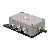
HYDAC FILTER SYSTEMS CSI-C-11-0-0-0/-000 Operating Instruction (84 pages)
ConditionSensor Interface
Brand:
HYDAC FILTER SYSTEMS
| Category:
Recording Equipment
| Size: 4 MB
Table of Contents
Table of Contents
3
1 General
6
Target Group of the Manual
6
Tab. 1 Target Group
6
Illustrations in the Manual
7
Illustration on the Title Page
7
Fig. 1 Overview / Labeling of the Title Page
7
Representation of Procedural Instructions
8
Representation of Requirements
8
Representation of Intermediate Results/Results
9
Representation of Warning/General Safety Information
10
Signal Words and Their Meaning in the General Safety Information
11
Supplementary Symbols
12
Exclusion of Liability/Warranty
12
Notes on Copyright
13
2 Safety
14
Observing Environmental Precautions
14
Danger Notifications
14
3 Performance Overview
16
Scope of Delivery
17
Tab. 2 Scope of Delivery
17
Dimensions
18
Fig. 2 CSI-C-11 Dimensions
18
Proper/Designated Use
19
Improper Use or Use Deviating from Intended Use
20
Technical Data
21
Tab. 3 Input Data
21
Tab. 4 Outputs
21
Tab. 5 Electrical Data
22
Tab. 6 Internal Measurement Data Memory
22
Tab. 7 Other Data
22
Decoding the Model Code Label
23
Fig. 3 Type Label
23
Tab. 8 Decoding the Model Code Label
23
Model Code
24
Fig. 4 Model Code CSI
24
Sensor Overview and Functions
25
Fig. 5 Connection Overview
26
4 Storage and Transport
27
5 Assembly, Installation and Commissioning
28
Assembling the CSI
28
Fig. 6 Assembling the CSI
28
Fig. 7 Example: CSI-C-11 Assembled on a CSM-E
29
Fig. 8 Example: CSI-C-11 Assembled on a Motor-Pump Assembly
29
Connection Overview
30
Fig. 9 Connection Overview
30
Pin Assignment - DC in / HSI
31
Pin Assignment - Sensor 1 in
31
Fig. 10 DC in / HSI
31
Fig. 11 Sensor 1 in
31
Tab. 9 Pin Assignment - DC in / HSI
31
Tab. 10 Pin Assignment - Sensor 1 in
31
Pin Assignment - LAN
32
Pin Assignment - Sensor 2 in
32
Fig. 12 Sensor 2 in
32
Fig. 13 LAN
32
Tab. 11 Pin Assignment - Sensor 2 in
32
Tab. 12 Pin Assignment - LAN
32
Connection Examples
33
Fig. 14 Connection Example CSI
33
Fig. 15 Connection Example CSI-C-11 - CS1000 - Hda48X6-A - ETS7246-B
34
Fig. 16: Connection Example ZBE CSI 60
35
Fig. 24 ZBE CSI 60 Connection Adapter
35
Commissioning
36
Setting CSI Via Flumos Mobile
36
Setting the CSI
36
Setting the CSI Via LAN
36
Setting the CSI Via W-LAN
37
Tab. 13 Default Settings of the Web Server
37
6 Factory Settings
38
Description of the Factory Settings
38
Tab. 14 Description of the Factory Settings
41
Overview of the Factory Settings
42
Tab. 15 Factory Settings for CSI-C-11-0-0-1/-000
44
7 Operation
45
Fig. 17 Status LED
45
Evaluating/Reading Measurement Protocols/Values
46
Evaluating/Reading Measurement Reports/Values with Flumos
46
Reading Measurement Protocols/Values Via Modbus
48
Input Register Mapping - New Format
49
Tab. 16 Input Register Mapping - New Format
50
Input Register Mapping - Old Format
51
Tab. 17 Input Register Mapping - Old Format
52
Input Register Map - Example with Sensors CS1000 and AS1000
53
Fig. 18 Input Register Map - Example with Sensors CS1000 and AS1000
53
Reading Measurement Protocols Via FTP
54
Reading Measurement Protocols/Values Via Flumot
54
Evaluating / Reading the Signal Light
54
Method for the Determination of Contamination Limit Values According to ISO 12669
55
Method for the Determination of Contamination Limit Values According to the Contamination Handbook
55
Sending an E-Mail Notification
55
Example - E-Mail Settings on the Web Server
56
Fig. 19 Example: E-Mail Settings
56
Open/Operate the Web Interface
57
Open/Display/Operate the Web Interface Via LAN
57
Fig. 20 Web Interface Via LAN
58
Opening/Displaying/Operating the Web Interface Via LAN
59
Fig. 21 Web Interface Via W-LAN
59
Sending Measured Data to the CMX
60
Fig. 22 CMX Settings Example for the Settings for the CMX
60
Changing the Access Data for the Web Interface and FTP
62
8 Performing Maintenance
63
9 Troubleshooting/Fault Rectification
64
Tab. 18 Troubleshooting
66
Fig. 23 Signal Light - Evaluating/Reading the Error Code
67
10 Removing / Disposal
68
A Appendix
69
Contacting Customer Service
69
Tab. 19 HYDAC Service Deutschland
69
Accessories
70
Tab. 20 Connection Cable - Socket <-> Plug
70
Tab. 21 Connection Cable - Socket <-> Open End
71
Tab. 22 Connection Cable - Plug <-> Open End
71
ZBE CSI 60 Connection Adapter - Connection Overview
73
Table of Illustrations
75
Glossary
78
Index
81
Advertisement
HYDAC FILTER SYSTEMS CSI-C-11-0-0-0/-000 Operating Instruction (72 pages)
ConditionSensor Interface
Brand:
HYDAC FILTER SYSTEMS
| Category:
Recording Equipment
| Size: 3 MB
Table of Contents
Table of Contents
2
1 General
5
Imprint
5
Documentation Representative
5
Tab. 1 Impressum
5
Tab. 2 Documentation Representative
5
Purpose of this Manual
6
Target Group of the Manual
6
Tab. 3 Target Group
6
Target Group - Required Qualifications/Training
7
Tab. 4 Required Qualifications/Training
7
Illustrations in the Manual
8
Illustration on the Title Page
8
Fig. 1 Overview / Labeling of the Title Page
8
Representation of Procedural Instructions
9
Representation of Requirements
9
Representation of Intermediate Results/Results
10
Representation of Warning/General Safety Information
11
Signal Words and Their Meaning in the General Safety Information
12
Representation/Explanation of Pictograms
13
Supplementary Symbols
14
Exclusion of Liability/Warranty
14
Notes on Copyright
15
Validity of this Manual
15
2 General Safety Information
16
3 Product Overview
18
Scope of Delivery
19
Tab. 5 Scope of Delivery
19
Dimensions
20
Fig. 2 CSI-C-11 Dimensions
20
Proper/Designated Use
21
Improper Use or Use Deviating from Intended Use
22
Technical Data
23
Tab. 6 Input Data
23
Tab. 7 Outputs
23
Tab. 8 Electrical Data
24
Tab. 9 Internal Measurement Data Memory
24
Tab. 10 Other Data
24
Decoding the Model Code Label
25
Fig. 3 Type Label
25
Tab. 11 Decoding the Model Code Label
25
Model Code
26
Fig. 4 Model Code CSI
26
4 Storage and Transport
27
5 Assembly, Installation and Commissioning
28
Assembling the CSI
28
Fig. 5 Assembling the CSI
28
Fig. 6 Example: CSI-C-11 Assembled on a CSM-E
29
Fig. 7 Example: CSI-C-11 Assembled on a Motor-Pump Assembly
29
Connection Overview
30
Fig. 8 Connection Overview
30
Pin Assignment - DC in / HSI
31
Pin Assignment - Sensor 1 in
31
Fig. 9 DC in / HSI
31
Fig. 10 Sensor 1 in
31
Tab. 12 Pin Assignment - DC in / HSI
31
Tab. 13 Pin Assignment - Sensor 1 in
31
Pin Assignment - LAN
32
Pin Assignment - Sensor 2 in
32
Fig. 11 Sensor 2 in
32
Fig. 12 LAN
32
Tab. 14 Pin Assignment - Sensor 2 in
32
Tab. 15 Pin Assignment - LAN
32
Connection Examples
33
Fig. 13 Connection Example CSI
33
Fig. 14 Connection Example CSI-C-11 - CS1000 - Hda48X6-A - ETS7246-B
34
Fig. 15: Connection Example ZBE CSI 60
35
Commissioning
36
Parameterizing the CSI Via a Web Server
36
Parameterizing the CSI Via Flumos Mobile (Android)
36
Parametrizing the CSI
36
Tab. 16 Factory Settings of the Web Server
36
6 Factory Settings
38
Description of the Factory Settings
38
Tab. 17 Description of the Factory Settings
40
Overview of the Factory Settings
41
7 Operation
44
Fig. 16 Status LED
44
Evaluating/Reading Measurement Protocols/Values
45
Evaluating/Reading Measurement Reports/Values with Flumos
45
Reading Measurement Protocols/Values Via Modbus
47
Mapping - New Format
48
Tab. 19 Mapping - New Format
49
Mapping -Old Format
50
Tab. 20 Mapping - Old Format
51
Example with CS1000 / AS1000
52
Fig. 17 Example: Sensor Dialog
52
Reading Measurement Protocols Via FTP
53
Reading Measurement Protocols/Values Via Flumot
53
Evaluating / Reading the Signal Light
53
Sending an E-Mail Notification
53
Example - E-Mail Settings on the Web Server
54
Fig. 18 Example: E-Mail Settings
54
8 Performing Maintenance
55
9 Troubleshooting/Fault Rectification
56
Fig. 19 Signal Light - Evaluating / Reading the Error Code
58
10 Removing / Disposal
59
11 Appendix
60
Accessories
60
Tab. 22 Connection Cable - Socket <-> Plug
60
Tab. 23 Connection Cable - Socket <-> Open End
61
Tab. 24 Connection Cable - Plug <-> Open End
61
ZBE CSI 60 Connection Adapter - Connection Overview
63
Fig. 20 ZBE CSI 60 Connection Adapter
63
Table of Illustrations
65
Glossary
68
Index
71
Advertisement
Related Products
HYDAC FILTER SYSTEMS CSI-C-11
HYDAC FILTER SYSTEMS CSM-E
HYDAC FILTER SYSTEMS ContaminationSensor CS 1939 Series
HYDAC FILTER SYSTEMS ContaminationSensor CS 1939-0-0/-000
HYDAC FILTER SYSTEMS CSM 1000 Series
HYDAC FILTER SYSTEMS CTU 1 3 Series
HYDAC FILTER SYSTEMS CTM-EB 14 Series
HYDAC FILTER SYSTEMS CMP 43 0-5 Series
HYDAC FILTER SYSTEMS CMP1000 Series
HYDAC FILTER SYSTEMS CMP1 0-4-1 Series
HYDAC FILTER SYSTEMS Categories
Water Filtration Systems
Control Unit
Industrial Equipment
Measuring Instruments
Test Equipment
More HYDAC FILTER SYSTEMS Manuals
Login
Sign In
OR
Sign in with Facebook
Sign in with Google
Upload manual
Upload from disk
Upload from URL