Sign In
Upload
Manuals
Brands
Hioki Manuals
Test Equipment
ST4030A
Hioki ST4030A Manuals
Manuals and User Guides for Hioki ST4030A. We have
2
Hioki ST4030A manuals available for free PDF download: Instruction Manual, Manual
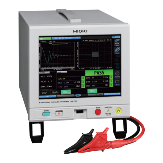
Hioki ST4030A Instruction Manual (256 pages)
Impulse Winding Tester
Brand:
Hioki
| Category:
Test Equipment
| Size: 16 MB
Table of Contents
Table of Contents
5
Introduction
9
Notations
10
Confirming Package Contents
11
Options (Sold Separately)
12
Usage Notes
13
1 Overview
15
Features
15
Parts Names and Functions
16
Screen Operations
18
Measuring Mode Settings
18
Moving Windows
19
Touch Keyboard Inputs
19
Screen Configuration
20
2 Preparation for Measurements
21
Connecting the Test Lead (on the ST4030)
22
Connecting the Power Cord
23
Power Supply ON/OFF
24
Main Power Supply on
24
Main Power Supply off
24
Sleep Mode
25
Startup Mode
25
Select Measuring Mode
26
Inspecting before Measurement and Verifying Operations
27
Inspection
27
Checking the Voltage Generated
28
Checking the Impulse Response Waveforms
29
Overview
33
Overview of Test Conditions Switching Functions
33
Items that Can be Saved
34
Operations Flowchart in Test Conditions Settings Mode and Test Mode
35
Screen Configuration
36
Current Table Selection
37
Changing the Table Name
40
4 Setting the Test Conditions
43
Overview
43
Operations Flowchart in Test Conditions Settings Mode
43
Screen Configuration
44
Applied Voltage
49
Number of Applied Pulses
50
Sampling Frequency/Number of
52
Sampling Data
52
Automatic Settings for Range of Waveform Acquisition
54
Trigger Delay
55
Voltage Calibration
57
5 Setting Judgment Conditions
59
Overview
59
Judgment Types
59
Settings Operations Procedure
60
LC and RC Values Area Judgments [LCRC AREA]
61
Enabling the LC and RC Values Judgments Function
63
Importing LC and RC Master Values
64
Auto Creation of the PASS Judgment Area
66
Manually Creating the PASS Judgment Area
68
Waveform Judgments
70
Surface Area Comparison Judgments [AREA]
70
Differential Surface Area Comparison Judgments [DIFF AREA]
72
Flutter Detection Judgments [FLUTTER]
74
Secondary Differential Detection Judgments [LAPLACIAN]
77
Waveform Judgment Area and Judgment Threshold Value Automatic Settings Functions
79
Discharge Judgments (When Incorporating Model ST9000)
80
Discharge Judgment Methods [DISCHARGE]
81
Threshold Value of the Test Waveform Discharge Amount over the Master Waveform Discharge Amount
82
Deviation Threshold Value of the Test Waveform Discharge Amount
83
Setting the Discharge Amount Judgment Area
84
6 Implementing Tests
85
Overview
85
Operations Flowchart in Test Mode
85
Screen Configuration
86
Checking Test Start and Test Results
92
7 Break down Voltage Test (BDV)
93
Overview
93
Operations Flowchart in Break down Voltage Test Mode
93
Screen Configuration
94
Checking Test Start and Test Results
97
Setting the Test Conditions
98
Applied Voltage Settings
98
Number of Applied Pulses Settings
99
Setting the Sampling Frequency and Number of Sampling Data
101
Setting the Waveform Acquisition Area Automatically
102
Setting Dielectric Break down Judgment Conditions
103
LC and RC Values Judgments
103
Discharge Judgment
104
Waveform Surface Area Comparison Judgment
105
Peak Voltage Value Fluctuations
106
Vibration Frequency Fluctuations
107
8 Other Functions
109
Interlock Function
109
Unlocking the Interlocks
111
Key Lock Function
112
Unlocking the Key Locks
113
Double Action Function
114
Memory Function
115
Memory Function Settings (ON/OFF)
116
Saving Memory Data
117
Deleting Memory Data
118
Displays
119
Graph Display Settings
120
Overlay Settings
120
Waveform Color Settings
121
LC and RC Graph Scale Settings
123
Implementing the LC and RC Graph Auto Scale
124
Judgment Beep
125
Key Beep
126
Test Time (EOM) Display
127
Communications Commands Long Format Settings
128
Initializing the Instrument (System Reset)
129
Terminal Open Error Setting
130
Voltage Error Setting
131
9 System Settings
133
Instrument System Information
133
Self-Test Function
134
Touch Panel Test
134
Touch Panel Correction
135
Screen Display Test
136
ROM/RAM Test
137
EXT. I/O Test
139
Date and Time Settings
140
10 External Control
141
(Ext. I/O)
141
External Control Measurement Flow
142
Sinking Current (NPN) / Sourcing Current (PNP)
143
Connection (Instrument and Control Devices)
144
Instrument Connector and Compatible Connectors
144
Signal Functions
146
Internal Circuit Configuration
147
Electrical Specifications
148
Connection Examples
148
Timing Chart
150
Explanation of Timing Chart Times
150
Measurement Timing Example
151
Flow of Starting Measurements from an External Device, and Reading the Judgment Results
152
11 Communications Interface
153
Overview
154
Screen Display
154
Specifications
155
Gp-Ib
156
Usb
156
Lan
156
Total
156
Mounting and Removing an Interface
157
Interface Settings
159
Connecting and Setting RS-232C (Model Z3001)
160
Connecting and Setting GP-IB (Model Z3000)
162
Connecting and Setting USB
163
Setting and Connecting LAN
165
Connection Method
165
Setting Procedure
167
Remote Mode
170
Communications Monitor
171
12 USB Host
173
Overview
173
Removing the USB Memory
174
File Window
176
Settings for Saving the Data
177
Setting Auto Save
177
Setting Manual Save
178
Text Save Items Settings
179
Setting the Text Save Format
180
Setting the Image Save Format
181
Setting the Name of the Saved File and Its Folder
182
Saving Test Results
184
Saving Manually
184
Checking the Test Results that Have Been Saved
186
Saving and Importing Test Conditions
188
Saving Test Conditions
188
Importing Test Conditions
190
Editing Files and Folders
192
Formatting USB Memory
192
Deleting Files and Folders
194
Creating Folders
195
Changing the Folder Name and File Name
196
Information Display
197
Specifications
199
General Specifications
199
Input Specifications/Output Specifications/Measurement Specifications
200
Basic Specifications
200
Accuracy Specifications
200
Functional Specifications
201
Test Conditions Settings
201
Set Judgment Conditions
201
Test Conditions Switching Functions
203
Break down Voltage Test (BDV) Mode
204
Safety Protection Function
205
Other Functions
206
Interface Specifications
208
External Control Terminal (EXT.I/O) Specifications
208
Communications Interface Specifications
210
USB Host Specifications
211
Test Time (Reference Value)
212
L2250 Clip Type Lead (Option)
213
General Specifications
213
Basic Specifications
213
L2252 Unprocessed Lead Cable (Option)
213
14 Maintenance and Service
215
Troubleshooting
216
Before Sending the Instrument for Repair
216
FAQ Regarding External Control (EXT. I/O)
220
Initializing the Instrument (Full Reset)
221
Error Display
222
Discarding the Instrument (Removing the Lithium Battery)
228
15 Appendix
229
Block Diagram
229
Circuit Configuration
230
Circuit Operations During Tests
230
Effects of Cable Parasitic Components
231
Rack Mount
232
Metal Fitting Dimensions
233
Installation Method
235
Dimensions Diagram
237
Repeat Accuracy (Reference Value)
238
Reproducibility of the Voltage Generated
238
Oscillation Waveform Reproducibility
239
Max. Applicable Voltage (Reference Value) According to the Workpiece Inductance
240
Voltage Switching Time (Reference Value)
241
Waveform Differences (Typical Values) between Instruments
242
Affects on Measurements According to the Length of the Test Lead
244
Precautions When Processing Test Leads
245
Ver. 1.01 Compatibility Function
247
Index
249
Advertisement
Hioki ST4030A Manual (48 pages)
IMPULSE WINDING TESTER
Brand:
Hioki
| Category:
Test Equipment
| Size: 2 MB
Table of Contents
Table of Contents
3
Overview
5
Selecting the Measurement Mode
6
Rise Time
7
Waveform Graph Display
7
Setting the Rise Time Calculation Formula
8
Waveform Trigger Position
9
Setting Waveform Trigger Positions
9
Automatically Setting the Waveform Judgment Scope and Judgment Threshold Values
11
Automatically Setting the Waveform Judgment Scope
12
Automatically Setting the Waveform Judgment Threshold Values
13
Waveform Judgment Threshold Values Formulas
15
Compatibility of Automatically Configured Waveform Judgment Scope and Judgment Threshold Values
16
Continuous Application
17
Enabling Continuous Application
17
Discharge Starting Voltage Testing (RPDIV)
18
Screen Configuration
18
Starting Testing and Checking Test Results
19
Recorded Data Display
21
Applied Voltages
22
Number of Applied Pulses
23
Sampling Frequency and Number of Sampling Data
24
Return Conditions
25
Rise Time
26
Trigger Position
27
Discharge Starting Voltage Judgment Conditions
28
Automatic Voltage Adjustment
29
Global Automatic Voltage Adjustment
30
Screen Display
32
Manual Voltage Adjustment
33
Screen Display
34
Degaussing Pulse/Measurement Pulse Detection Signal Output
35
Extension to Area Detection Threshold Settings
36
Screen Display
38
Fixing Startup Mode
39
Permanently Enabling the Interlock Function
40
Permanently Enabling Level Operation of the EXT. I/O STOP Pin
40
Background Color
41
Auto Saving of Files
42
Extension to the Voltage Error Setting
43
Expansion of System Information
44
Other Changes
45
Communication Commands
45
BDV Mode
45
File Screen
45
STOP Button
45
Downgrading
45
Advertisement
Related Products
Hioki ST4030
Hioki ST5540
Hioki ST5541
Hioki SM7810
Hioki SM7810-20
Hioki ST5520-01
Hioki ST5520
Hioki ST5680
Hioki SR-2
Hioki ST4200
Hioki Categories
Measuring Instruments
Test Equipment
Data Loggers
Multimeter
Accessories
More Hioki Manuals
Login
Sign In
OR
Sign in with Facebook
Sign in with Google
Upload manual
Upload from disk
Upload from URL