Sign In
Upload
Manuals
Brands
Hioki Manuals
Measuring Instruments
3197
Hioki 3197 Manuals
Manuals and User Guides for Hioki 3197. We have
2
Hioki 3197 manuals available for free PDF download: Instruction Manual, Measurement Manual
Hioki 3197 Instruction Manual (200 pages)
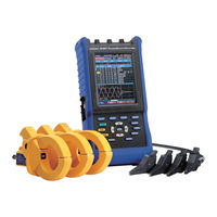
POWER QUALITY ANALYZER
Brand:
Hioki
| Category:
Measuring Instruments
| Size: 6 MB
Table of Contents
Table of Contents
3
Introduction
9
Confirming Package Contents
10
9418-15 AC Adapter
11
9459 Battery Pack
11
Safety Information
12
Operating Precautions
15
Operating Procedure Descriptions in this Manual
20
Chapter 1 Overview
21
Product Overview
21
Features
22
Measurement Flowchart
25
Initial Instrument Preparations
27
Install and Connect the Instrument, and Turn the Power on
27
Other Preparations
27
Confirming Instrument Settings and Connecting to the Lines to be Measured
28
Start Recording and Analyze Recorded Measurement Data
29
Chapter 2 Names and Functions of Parts and Basic Setup
31
Panel and Operating Keys
31
Basic Operations
35
Screen Configurations
36
Common Screen Elements
40
Internal Operating Status and Memory Usage
42
When Memory Partitioning Is Disabled (Partition: [OFF])
42
Using Memory Partitioning (Partition: [ON])
43
Chapter 3 Measurement Preparations
45
Initial Instrument Preparations
45
Apply the Appropriate Label to the Input Terminals
45
Apply the Appropriate Labels to the Voltage Measurement and Clamp Sensor Leads
46
Attach the Strap
46
Install the 9459 Battery Pack
47
Charge the 9459 Battery Pack
48
Connecting the AC Adapter
49
Connecting the Voltage Cords
50
Connecting Clamp Sensors
52
Turning the Power on and off
54
Other Preparations
56
Select the Screen Color Scheme to Match the Input Terminal Labels
56
Select the Naming Convention to be Applied to each Phase Line Measurement on the Display
57
Auxiliary Function (KEY LOCK)
59
Auxiliary Function (Save Screen Image)
60
Chapter 4 Pre-Measurement and System Settings
61
Basic Setup (Typical Settings)
62
Selecting the Measurement Method (SYSTEM Screen)[Measure]
65
Selecting the Line Frequency (Frequency)
66
Setting the Wiring Method (Wiring)
66
Setting the Line Voltage (Nominal Line Voltage) of the Lines to be Measured
67
Selecting the Clamp Sensor Model and Current Range
68
Setting the PT Ratio (When Measuring Using a Transformer)
69
Setting the CT Ratio (When Measuring Using a Transformer)
69
Selecting the Voltage Harmonic Calculation Method
70
Selecting the Power Factor Calculation Method (PF Type)
70
Setting the Recording Method[Rec&Event]
71
Setting the Method for Recording to Internal Memory (Partition)
71
Setting the Recording Interval (Interval)
72
Setting Demand Period
73
Setting Recording Start and Stop Times
74
Setting Event Detection [REC&EVENT]
75
Start Event/ Stop Event
76
Manual Events
76
Setting Timed Events
77
Setting Inrush Events
77
Setting Transient Events
78
Setting Voltage Swell, Dip and Interruption Events
79
Changing Instrument System Settings [SYSTEM]
80
Displaying the Instrument's Version Number (Version)
80
Changing the Display Language (Language)
81
Changing Screen Colors (Color)
81
Enable or Disable Beep Sounds (Beep)
82
Setting the LCD Backlight Timeout (Backlight)
82
Adjusting Screen Contrast (Contrast)
83
Setting the Clock (Clock)
84
Viewing the Serial no
84
Initializing the Instrument (System Reset)
85
Chapter 5 Making Connections and Starting & Stopping Measurement
87
Pre-Operation Inspection
87
Connecting to the Lines to be Measured
89
L9438-55 Voltage Cord (Four Black Voltage Cords)
89
Verifying Correct Wiring (Connection Check)
94
Starting and Stopping Recording
96
Starting and Stopping Recording Without Memory Partitioning (Partition: OFF)
97
Starting and Stopping Recording with Partitioned Memory (Partition: ON)
100
Erasing Data
101
Recovering from a Long-Term Power Outage
102
Chapter 6 Viewing Data
103
Viewing Instantaneous Data (VIEW Screen)
104
Holding the Screen Display
104
Viewing Waveforms [WAVEFORM]
105
Vector Display [VECTOR]
106
Displaying Harmonics [HARMONICS]
107
Displaying the DMM Screen (Voltage, Current and Instantaeous Power Values)[DMM]
109
Displaying a Time Series Plot (TIME PLOT Screen)
110
Common Operations and Screen Items (Common to TIME PLOT Screens)
110
Displaying the Rms Fluctuation Graph [RMS]
111
Displaying a Voltage Fluctuation Graph [DIP/SWELL]
113
Displaying a Demand Graph [DEMAND]
114
Displaying an Energy Consumption Graph [ENERGY]
115
Viewing Anomalous Phenomena (EVENT Screen)
116
Viewing the [RMS WAVE] Screen
116
Viewing the [INRUSH] Screen
117
Detection Methods and Recording Contents of Events
118
Operations Common to the EVENT Screens
122
Viewing Event Detection Details [DETAILS]
125
Displaying Detected Event Waveforms [WAVEFORM]
128
Displaying Detected Voltage Fluctuation Events [RMS WAVE]
129
Displaying Detected Inrush Current Events [INRUSH]
130
Viewing Recorded Data ([REVIEW] State)
131
Viewing Only Data Recorded in Memory Partition No. 1
131
Viewing Data Recorded in Multiple Memory Partitions
132
Analyzing TIME PLOT Data
133
Analyzing EVENT Data
133
Chapter 7 Viewing Data on a Computer
135
Overview
135
PC System Requirements
136
Files on the CD
136
Preparing to Run the Application Programs
137
Running the Application Programs
137
Installing JRE
138
Installing the Application Programs
140
Connecting the Instrument and Computer with the Supplied USB Cable
142
Starting the Instrument Application Programs
146
Chapter 8 Specifications
147
General Specifications
147
Accessories
151
Instruction Manual
151
Measurement Guide
151
Measurement Lead Labels
151
Input Terminal Labels
151
Detailed Specifications of Measurement Parameters
152
Event Specifications
158
Function Specifications
160
Calculation Formulas
164
Chapter 9
171
Maintenace and Service
171
Troubleshooting
171
Cleaning
173
Battery Pack Replacement and Disposal
174
Disposing of the Instrument
175
Appendix
177
Appendix 2 Relation between Graph Divisions and Time
181
Appendix 3 3197 Data-Header Composition
183
Appendix 4 Displayed and Measurement Ranges
184
Appendix 5 Power Range Structure
185
Appendix 6 Clamp Sensor Combined Accuracy
186
Appendix 7 How to Resolve USB Data Transfer Problems
187
Usbcable
187
Appendix 8 List of Settings (Default Settings)
189
Appendix 9 Definitions
190
Detecting Anomalies and Phenomena Due to Drops in Power Quality
190
Power Measurement by the Two-Meter Method, and U3, I3 Measurement Theory
192
Terminology
194
Index
197
Advertisement
Hioki 3197 Measurement Manual (2 pages)
Power Quality Analyzer
Brand:
Hioki
| Category:
Measuring Instruments
| Size: 0 MB
Table of Contents
Step 1. Preparation
1
Step 2. Setting up
1
Step 3. Recording
1
Step 4. Viewing Instantaneous Data
2
Step 5. Viewing Recorded Measurement Data
2
Step 6. Viewing Recorded Data (Measurement Data, Screen Image) on a Computer
2
Advertisement
Related Products
Hioki 3196
Hioki 3169-20
Hioki 3169-21
Hioki 3143
Hioki 3151
Hioki 3157
Hioki 3157-01
Hioki 3181-01
Hioki HITESTER 3184
Hioki 3155-01
Hioki Categories
Measuring Instruments
Test Equipment
Data Loggers
Multimeter
Accessories
More Hioki Manuals
Login
Sign In
OR
Sign in with Facebook
Sign in with Google
Upload manual
Upload from disk
Upload from URL