Sign In
Upload
Manuals
Brands
HEIDENHAIN Manuals
Control Systems
TNC 430 CE
HEIDENHAIN TNC 430 CE Manuals
Manuals and User Guides for HEIDENHAIN TNC 430 CE. We have
1
HEIDENHAIN TNC 430 CE manual available for free PDF download: User Manual
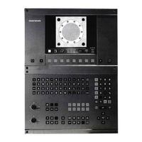
HEIDENHAIN TNC 430 CE User Manual (362 pages)
Brand:
HEIDENHAIN
| Category:
Control Systems
| Size: 9.32 MB
Table of Contents
Table of Contents
8
1 Introduction
17
The TNC 426 B, the TNC 430
18
Visual Display Unit and Keyboard
19
Modes of Operation
21
Status Displays
23
Accessories: HEIDENHAIN 3-D Touch Probes and Electronic Handwheels
27
2 Manual Operation and Setup
29
Switch-On, Switch-Off
30
Moving the Machine Axes
31
Spindle Speed S, Feed Rate F and Miscellaneous Functions M
33
Datum Setting (Without a 3-D Touch Probe)
34
Tilting the Working Plane
35
3 Positioning with Manual Data Input (MDI)
39
Programming and Executing Simple Machining Operations
40
4 Programming: Fundamentals of Nc, File Management, Programming Aids, Pallet Management
43
Fundamentals of NC
43
File Management: Fundamentals
49
Standard File Management
50
File Management with Additional Functions
56
Creating and Writing Programs
69
Interactive Programming Graphics
73
Structuring Programs
74
Adding Comments
75
Creating Text Files
76
Integrated Pocket Calculator
79
HELP for NC Error Messages
80
Managing Pallet Tables
81
5 Programming: Tools
84
Entering Tool-Related Data
84
Tool Data
85
Tool Compensation
94
Three-Dimensional Tool Compensation
98
Working with Cutting Data Tables
100
6 Programming: Programming Contours
108
Overview of Tool Movements
108
Fundamentals of Path Functions
109
Contour Approach and Departure
112
Overview: Types of Paths for Contour Approach and Departure
112
Important Positions for Approach and Departure
112
Approaching on a Straight Line with Tangential Connection: APPR LT
113
Approaching on a Straight Line Perpendicular to the First Contour Point: APPR LN
114
Approaching on a Circular Arc with Tangential Connection: APPR CT
114
Appr Lct
115
Departing Tangentially on a Straight Line: DEP LT
116
Departing on a Straight Line Perpendicular to the Last Contour Point: DEP LN
116
Departing Tangentially on a Circular Arc: DEP CT
117
Departing on a Circular Arc Tangentially Connecting the Contour and a Straight Line: DEP LCT
117
Path Contours - Cartesian Coordinates
118
Overview of Path Functions
118
Straight Line L
119
Inserting a Chamfer CHF between Two Straight Lines
119
Circle Center CC
120
Circular Path C Around Circle Center CC
121
Circular Path CR with Defined Radius
122
Circular Path CT with Tangential Connection
123
Corner Rounding RND
124
Example: Linear Movements and Chamfers with Cartesian Coordinates
125
Example: Circular Movements with Cartesian Coordinates
126
Example: Full Circle with Cartesian Coordinates
127
Polar Coordinate Origin: Pole CC
128
Straight Line LP
129
Circular Path CP Around Pole CC
129
Circular Path CTP with Tangential Connection
130
Helical Interpolation
130
Example: Linear Movement with Polar Coordinates
132
Example: Helix
133
Path Contours - FK Free Contour Programming
134
Fundamentals
134
Graphics During FK Programming
134
Initiating the FK Dialog
135
Free Programming of Straight Lines
136
Free Programming of Circular Arcs
136
Auxiliary Points
138
Relative Data
139
Closed Contours
141
Converting FK Programs
141
Example: FK Programming 1
142
Example: FK Programming 2
143
Example: FK Programming 3
144
Path Contours - Spline Interpolation
146
7 Programming: Miscellaneous Functions
149
Entering Miscellaneous Functions M and STOP
149
Miscellaneous Functions for Program Run Control, Spindle and Coolant
150
Miscellaneous Functions for Coordinate Data
150
Miscellaneous Functions for Contouring Behavior
153
Smoothing Corners: M90
153
Insert Rounding Arc between Straight Lines: M112
154
Machining Small Contour Steps: M97
154
Machining Open Contours: M98
155
Feed Rate Factor for Plunging Movements: M103
156
Calculating the Radius-Compensated Path in Advance (LOOK AHEAD): M120
157
Superimposing Handwheel Positioning During Program Run: M118
158
Miscellaneous Functions for Rotary Axes
159
Feed Rate in MM/Min on Rotary Axes A, B, C: M116
159
Shorter-Path Traverse of Rotary Axes: M126
159
Reducing Display of a Rotary Axis to a Value Less than 360°: M94
160
Automatic Compensation of Machine Geometry When Working with Tilted Axes: M114
161
Maintaining the Position of the Tool Tip When Positioning with Tilted Axes (TCPM*): M128
162
Exact Stop at Corners with Nontangential Transitions: M134
163
Miscellaneous Functions for Laser Cutting Machines
164
Programming: Cycles
166
General Information on Cycles
167
Drilling Cycles
169
PECKING (Cycle 1)
169
DRILLING (Cycle 200)
171
REAMING (Cycle 201)
172
BORING (Cycle 202)
173
UNIVERSAL DRILLING (Cycle 203)
174
BACK BORING (Cycle 204)
176
TAPPING with a Floating Tap Holder (Cycle 2)
178
RIGID TAPPING (Cycle 17)
179
THREAD CUTTING (Cycle 18)
180
Example: Drilling Cycles
181
Cycles for Milling Pockets, Studs and Slots
183
POCKET MILLING (Cycle 4)
184
POCKET FINISHING (Cycle 212)
185
STUD FINISHING (Cycle 213)
187
CIRCULAR POCKET MILLING (Cycle 5)
188
CIRCULAR POCKET FINISHING (Cycle 214)
190
CIRCULAR STUD FINISHING (Cycle 215)
191
SLOT MILLING (Cycle 3)
193
SLOT with Reciprocating Plunge-Cut (Cycle 210)
194
CIRCULAR SLOT with Reciprocating Plunge-Cut (Cycle 211)
196
Example: Milling Pockets, Studs and Slots
198
Cycles for Machining Hole Patterns
200
CIRCULAR PATTERN (Cycle 220)
201
LINEAR PATTERN (Cycle 221)
202
Example: Circular Hole Patterns
204
Cycles
206
CONTOUR GEOMETRY (Cycle 14)
208
Overlapping Contours
208
CONTOUR DATA (Cycle 20)
210
PILOT DRILLING (Cycle 21)
212
ROUGH-OUT (Cycle 22)
213
FLOOR FINISHING (Cycle 23)
214
SIDE FINISHING (Cycle 24)
214
CONTOUR TRAIN (Cycle 25)
215
CYLINDER SURFACE (Cycle 27)
217
Example: Roughing-Out and Fine-Roughing a Pocket
219
Example: Pilot Drilling, Roughing-Out and Finishing Overlapping Contours
221
Example: Contour Train
223
Example: Cylinder Surface
225
Cycles for Multipass Milling
227
RUN DIGITIZED DATA (Cycle 30)
227
MULTIPASS MILLING (Cycle 230)
229
RULED SURFACE (Cycle 231)
231
Example: Multipass Milling
233
Coordinate Transformation Cycles
234
DATUM SHIFT (Cycle 7)
235
DATUM SHIFT with Datum Tables (Cycle 7)
236
MIRROR IMAGE (Cycle 8)
239
ROTATION (Cycle 10)
240
SCALING FACTOR (Cycle 11)
241
AXIS-SPECIFIC SCALING (Cycle 26)
242
WORKING PLANE (Cycle 19)
243
Example: Coordinate Transformation Cycles
248
Special Cycles
250
DWELL TIME (Cycle 9)
250
PROGRAM CALL (Cycle 12)
250
ORIENTED SPINDLE STOP (Cycle 13)
251
TOLERANCE (Cycle 32)
252
9 Programming: Subprograms and Program Section Repeats
255
Marking Subprograms and Program Section Repeats
255
Subprograms
255
Program Section Repeats
256
Program as Subprogram
257
Nesting
258
Subprogram Within a Subprogram
258
Repeating Program Section Repeats
259
Repeating a Subprogram
260
Example: Milling a Contour in Several Infeeds
261
Example: Groups of Holes
262
Example: Groups of Holes with Several Tools
263
10 Programming: Q Parameters
267
Principle and Overview
267
Part Families - Q Parameters in Place of Numerical Values
269
Describing Contours through Mathematical Functions
270
Trigonometric Functions
272
Calculating Circles
273
If-Then Decisions with Q Parameters
274
Checking and Changing Q Parameters
275
Additional Functions
276
Entering Formulas Directly
285
Preassigned Q Parameters
288
Example: Ellipse
291
Example: Concave Cylinder Machined with Spherical Cutter
293
Example: Convex Sphere Machined with End Mill
295
11 Test Run and Program Run
298
Graphics
299
Functions for Program Display in Program Run and Test Run
304
Test Run
304
Program Run
306
Optional Block Skip
311
12 Mod Functions
312
Selecting, Changing and Exiting the MOD Functions
313
Software Numbers and Option Numbers
314
Code Number
314
Setting the Data Interfaces
315
Ethernet Interface
319
Configuring PGM MGT
326
Machine-Specific User Parameters
326
Showing the Workpiece in the Working Space
326
Position Display Types
328
Unit of Measurement
328
Programming Language for $MDI
329
Selecting the Axes for Generating L Blocks
329
Axis Traverse Limits, Datum Display
329
Displaying HELP Files
330
Machining Times
331
13 Tables and Overviews
332
General User Parameters
333
Pin Layout and Connecting Cable for the Data Interfaces
348
Technical Information
352
Exchanging the Buffer Battery
355
Advertisement
Advertisement
Related Products
HEIDENHAIN TNC 430 PE
HEIDENHAIN TNC 415 B
HEIDENHAIN TNC 415 F
HEIDENHAIN TNC 425 E
HEIDENHAIN TNC 426 CA
HEIDENHAIN TNC 426 PA
HEIDENHAIN TNC 426 CE
HEIDENHAIN TNC 426 CF
HEIDENHAIN TNC 426 PF
HEIDENHAIN TNC 426 B
HEIDENHAIN Categories
Media Converter
Measuring Instruments
Industrial Equipment
Control Systems
Controller
More HEIDENHAIN Manuals
Login
Sign In
OR
Sign in with Facebook
Sign in with Google
Upload manual
Upload from disk
Upload from URL