Sign In
Upload
Manuals
Brands
Hasler Manuals
Measuring Instruments
Sound 2
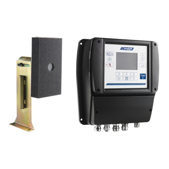
Hasler Sound 2 Digital Electronic Ear Manuals
Manuals and User Guides for Hasler Sound 2 Digital Electronic Ear. We have
2
Hasler Sound 2 Digital Electronic Ear manuals available for free PDF download: Instruction Manual, Commissioning Manual
Hasler Sound 2 Instruction Manual (65 pages)
Brand:
Hasler
| Category:
Measuring Instruments
| Size: 3 MB
Table of Contents
Table of Contents
7
1 Introduction
11
Document Purpose
11
General Safety Instructions
11
Supporting Documents
11
Regulations and Standards
11
Intended Use
11
Target Audience
11
Contraindications
11
Glossary of Pictograms Used
12
Abbreviations
12
2 Description and Principle of Operation
13
Overview of the System
13
Description of the Unit
13
Presentation of the Screen on the Unit
13
Figure 1: Composition of the SOUND2 System
13
Figure 2: Presentation of the Screen on the Unit
14
Figure 3: Main Page
14
Circuit Board
16
Figure 4: Circuit Board
16
Characteristics of the Digital Outputs
17
Characteristics of the Analogue Outputs
17
Figure 5: Characteristics of the Digital Outputs
17
Figure 6: Characteristics of the Analogue Outputs
17
Sound 2 Version
18
Operation
18
Characteristics
18
Technical Characteristics
18
CE Identification Plate
19
Figure 7: CE Identification Plate
19
3 Safety Instructions
20
General Information
20
European Directives
20
Basic Safety Instructions
20
Safety Instructions for Installation
20
Safety Instructions for Use
20
Safety Instructions for Maintenance
21
Safety Stickers
21
4 Transport-Handling-Storage-Installation Prerequisites
22
Transport
22
Handling
22
Storage
22
Installation Prerequisites
22
Checks after Receipt of the Machine
22
Checking that the Power Socket and Power Cable Are Earthed
22
5 Installation
24
Block Diagram of the Installation
24
Figure 8: Block Diagram of the Installation
24
Installing the Equipment
25
Installing the Unit
25
Figure 9: Overall Dimensions and Mounting System for the Unit
25
Installing the Microphone
26
Figure 10: Location of the Microphone
26
Figure 11: Overall Dimensions of the Microphone
26
Connections
27
Power Supply Cable
27
Figure 12: Composition of the Power Cable Connector
27
Microphone Cable (Use a Shielded 2-Wire Cable)
28
Figure 13: Connecting the Power Cable
28
Figure 14: DELTRON 592-0301 Connector
28
Figure 15: Microphone Cable (Two Wires with Shield) - Connector Assembly
28
Figure 16: Microphone Cable (Two Wires with Shield) - Inserting the Cable
29
Figure 17: Microphone Cable (Two Wires with Shield) - Soldering the Wires
29
Figure 18: Microphone Cable (Two Wires with Shield) - Fitting the Shield Wire
29
Figure 19: Microphone Cable (Two Wires with Shield) - Tightening the Screw
29
Figure 20: Microphone Cable (Two Wires with Shield) - Connecting to the Microphone
29
Figure 21: Connection on the PCB End (Two Wires with Shielding) - Wiring Diagram
30
Powering up
31
Setting the Sound 2 Parameters
31
Figure 22: Microphone Cable (Two Wires with Shielding) - Connecting the 2 Data Bus Wires
31
Figure 23: Microphone Cable (Two Wires with Shielding) - Earthing on the Cable Gland
31
Verification Prior to Initial Commissioning
32
Figure 24: "Parameters" Menu
32
Figure 25: Checking Calibration
32
Calibrating the Sound2
33
Initial Mill Status
33
Accessing Calibration Menu
33
Starting a Calibration Procedure
33
Figure 26: "Calibration" Menu
33
Figure 27: "Calibration in Progress" Menu
34
Saving the Configuration
35
Figure 28: Saving the Configuration
36
6 Use - Operation
37
Ntroduction
37
Satisfactory Conditions of Use
37
Contraindications Concerning the Use of the Machine
37
Production-Related Risks
37
Risks Associated with the Mechanical Integrity of the Machine
37
Risks Related to Personal Safety
37
Operation
38
Powering Up/Commissioning the Machine
38
Powering Down/Decommissioning the Machine
38
Using the Human Machine Interface
38
Structure of the Operator Menu
38
System" Menu
38
Figure 29: Operator Menu Structure
38
Figure 30: "System\General" Menu
39
Figure 31: "System\Security Level" Menu
39
Figure 32: Changing Profile
40
Figure 33: "System\Software Versions" Menu
40
Alarm" Menu
41
Measures" Menu
41
Figure 34: "Alarm History" Menu
41
Figure 35: "Measures" Menu
41
Figure 36: "Calibration Datas" Submenu
42
Figure 37: "Actual Measures" Submenu
42
Calibration" Menu
43
Figure 38: "Actual Measures" Submenu
43
7 Troubleshooting
44
Mechanical Troubleshooting
44
Software Troubleshooting
44
8 Maintenance
45
General Safety Instructions
45
Preventive Maintenance Plan
45
Corrective Maintenance Plan
45
Preventive Maintenance Procedures
46
Visual Inspection
46
Cleaning
46
Corrective Maintenance Procedures
47
Changing the Electronic Unit
47
Changing the Microphone
48
Figure 39: Importing the Configuration
48
Figure 40: Removing the Microphone
48
Changing the Microphone Mounting Bracket
49
Figure 41: Removing the Microphone Mounting Bracket
49
Sound2 Maintenance Menus
50
Structure of the Premium Maintenance Menu
51
Figure 42: Structure of the Premium Maintenance Menu
51
Structure of the Advanced Maintenance Menu
52
Figure 43: Structure of the Advanced Maintenance Menu
52
Alarm" Menu
53
Figure 44: "Communication Host" Submenu
54
Parameters" Menu
55
Measures" Menu
55
Calibration" Menu
55
Cross Talk" Menu
55
Figure 45: Example with Two Mills in the same Room
55
Figure 46: "Cross Talk" Menu
55
Outputs" Menu
56
Figure 47: "Analog Outputs" Menu
56
System" Menu
57
Figure 48: "Digital Outputs" Menu
57
Figure 49: "System\General" Menu
58
Figure 50: Definition of the Parameters on the Main Screen
59
Figure 51: "System\Parameters" Menu
59
Figure 52: "System\Security" Menu
60
Figure 53: Changing the "Maintenance" Password
60
8.6.10. "Diagnostics" Menu
61
Figure 54: "System\Communication" Menu
61
9 Spare Parts
63
Foreword
63
List of Spare Parts
63
Figure 55: List of Spare Parts
63
10 Declaration of Conformity/Incorporation
64
Advertisement
Hasler Sound 2 Commissioning Manual (32 pages)
Monitoring system for grinders
Brand:
Hasler
| Category:
Measuring Instruments
| Size: 1 MB
Table of Contents
Table of Contents
3
Introduction
5
Checking on Receipt
5
Caution
5
Supplies
6
Microphone Installation
7
Installation of the Electronic Housing
9
Mounting Shielded Cables in the Cable Glands
10
Cable Preparation
10
Cable Mounting
10
Connection Diagram
11
Electrical Interface
12
Connection
13
Power Supply Connection
13
Microphone Connection on Ear Side
14
Installation
15
Microphone Definitive Position
15
Microphone Connection on Sound2 Side
15
Calibration
17
Movement and Selection Keys
18
Sound 2 Configuration
19
Calibration Display
21
Calibration Procedure
22
Outputs Signals
23
Threshold Signals
25
Communication
26
Sub Dconnexions (Modbus Rtu)
27
Sub Dconnexions (Profibus Dp)
27
Ethernet Connexion (Modbus TCP)
28
Technical Specifications
29
Maintenance
30
Power Supply Connector
30
Update Software
30
Undesirable Frequency Influence
31
Advertisement
Related Products
Hasler Categories
Digital Mailing system
Printer
Postal Equipment
Measuring Instruments
Office Equipment
More Hasler Manuals
Login
Sign In
OR
Sign in with Facebook
Sign in with Google
Upload manual
Upload from disk
Upload from URL