Table of Contents
Advertisement
Advertisement
Table of Contents

Related Manuals for Hasler Sound 2


Summary of Contents for Hasler Sound 2
- Page 1 COMMISSIONING MANUAL ____________________________________________________________________________________ Sound 2 Monitoring system for grinders SOUND2.943.001-E.e __________________________________________________________________________________ Page 1/32 SOUND2.943.001-E.e...
- Page 2 HASLER Group, at the following number: +33 (0) 4 74 16 11 50. Information in this manual is correct as of the date of publication. HASLER Group assumes no responsibility for damages resulting from misuse of the equipment or negligence on the part of operating personnel.
-
Page 3: Table Of Contents
COMMISSIONING MANUAL ____________________________________________________________________________________ Table of contents INTRODUCTION ......................5 CHECKING ON RECEIPT ..................... 5 CAUTION .......................... 5 SUPPLIES.......................... 6 MICROPHONE INSTALLATION ................7 INSTALLATION OF THE ELECTRONIC HOUSING ..........9 MOUNTING SHIELDED CABLES IN THE CABLE GLANDS ......10 7.1. CABLE PREPARATION.................. - Page 4 COMMISSIONING MANUAL ____________________________________________________________________________________ __________________________________________________________________________________ Page 4/32 SOUND2.943.001-E.e...
-
Page 5: Introduction
COMMISSIONING MANUAL ____________________________________________________________________________________ Introduction Thank you very much for having chosen the monitoring system for mill Sound 2. This system has been used successfully on mill all over the world and will certainly work to your entire satisfaction and your plant. -
Page 6: Supplies
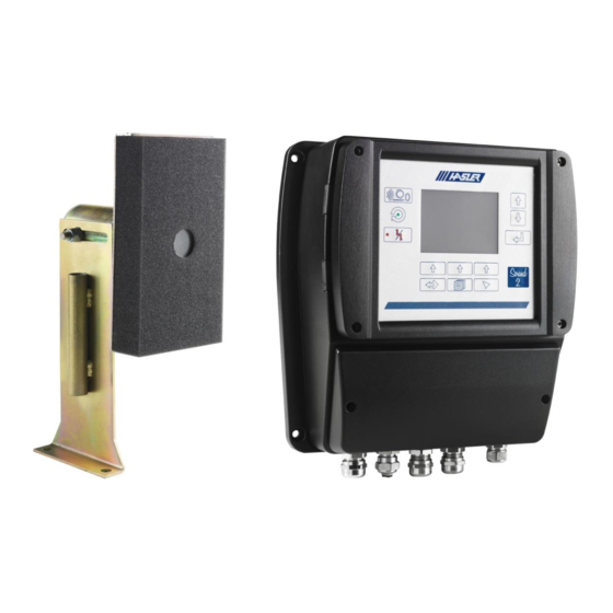
[2]: A connector for the microphone cable [3]: An electronic unit [4]: A connector for the power supply cable Connecting cables (not included): o Cable recommended: Standard Hasler reference: 0631.0007 (type LIYCY DIN47100 from NEXANS LIFLEX 2x0.22 or equivalent.) • Microphone cable Single pole, shielded type (Gauge A.W.G : 22-24) -
Page 7: Microphone Installation
COMMISSIONING MANUAL ____________________________________________________________________________________ Microphone Installation The microphone fitted with two holes (diameter 13mm) 120mm spacing, has to be set with a rigid support. Picture 1 : Microphone system dimensions Firstly, the needed cable length has to be determined and the microphone interface must be assembled. - Page 8 COMMISSIONING MANUAL ____________________________________________________________________________________ The microphone has to be placed under the mill at the ball’s impact point. The impact point is situated more or less at the “four o’clock” position (120° to 140°). Longitudinally, the area to monitor is situated at approximately 1 to 1.5m from the diaphragm, or at 2/3 of the first chamber.
-
Page 9: Installation Of The Electronic Housing
Installation of the electronic housing The electrical housing can be installed: • Near of the ball mill, on a wall of beam (remove the DIN rail mounting clip) • In a cabinet. The Sound 2 Electronic housing is guaranteed IP65. __________________________________________________________________________________ Page 9/32 SOUND2.943.001-E.e... -
Page 10: Mounting Shielded Cables In The Cable Glands
COMMISSIONING MANUAL ____________________________________________________________________________________ MOUNTING SHIELDED CABLES IN THE CABLE GLANDS 7.1. CABLE PREPARATION The interfaces are connected by shielded cables. These cables pass through shielded cable glands. Prepare the cable like below up to 9.5mm 7.2. CABLE MOUNTING Contact disks (D): Nickel plated brass. The threaded connector connects the shielding braid to the earthed unit. -
Page 11: Connection Diagram
COMMISSIONING MANUAL ____________________________________________________________________________________ Connection diagram AC/DC Converter in 230V Version DC/DC in 24V version Service Port Internal Power Supplies Filling Level Filling Level Microphone Cross Talk In Cross Talk Out Digital Outputs 0 – 10 V 0-4 / 20 mA J2 (1-2) J2 (3-4) J2 (5-6) -
Page 12: Electrical Interface
: Diaphony : Diaphony : Analog Output Communication 0/4-20mA Profibus DP MODBUS RTU Picture 5 : Sound 2 Interface All the electrical cables must be shielded. The shield must be connect to the ground reference (cable gland) __________________________________________________________________________________ Page 12/32 SOUND2.943.001-E.e... -
Page 13: Connection
(10A) upstream of Sound 2 supply line. The protection devices (Switch and current protector) must be accessible The name of the product :”Sound 2” Must be write visibly and near of the protection devices The power is fed through a round connector. -
Page 14: Microphone Connection On Ear Side
COMMISSIONING MANUAL ____________________________________________________________________________________ 10.2. Microphone connection on ear side Reference connector is DELTRON 592-0301 There is 6 elements Insert the two plastic pieces in the connector body Insert the cable into the connector Then put the pins into the connector body and connect the screw on the connector Now you can connect the connector to the microphone. -
Page 15: Installation
• After any important changes of the grinding balls. • At least once of years. 11.2. Microphone connection on Sound2 side Input – (Ground) Sound Input Input + Sound 2 Board __________________________________________________________________________________ Page 15/32 SOUND2.943.001-E.e... - Page 16 • Terminal Phoenix contact SPT2.5/2-V-5.0 (wire cross section: 0.14 to 2.5mm²) • Hasler reference 0631.0007 screened 2x0.75 mm cable are used: connect like this photo and connect the shield of this cable to the cable gland of the SOUND2 __________________________________________________________________________________ Page 16/32 SOUND2.943.001-E.e...
-
Page 17: Calibration
COMMISSIONING MANUAL ____________________________________________________________________________________ Calibration Calibration Wait Calibration 27.5°C Filling Level Down Max Frequency : 1857 Hz Alarm Max Power : 4560 Upper Threshold : 80% Enter Contextual selection Back Escape Menu Home Figure 7 : Functions keys on keyboard __________________________________________________________________________________ Page 17/32 SOUND2.943.001-E.e... -
Page 18: Movement And Selection Keys
COMMISSIONING MANUAL ____________________________________________________________________________________ 12.1. Movement and selection keys The “Main” page which is the default page out of any selected menu, can always be called directly with the key 'Home" To call the menu page, press the key "menu" To scroll up or down inside any list press the keys “Up” or “Down” located on the right side of the screen. -
Page 19: Sound 2 Configuration
COMMISSIONING MANUAL ____________________________________________________________________________________ 12.2. Sound 2 configuration Power on the Sound2, Press the Menu key (see Figure 6), then select System and Security. The following pages appear successively. The current security level is Operator. 27.5°C System 27.5°c Alarm General Parameters... - Page 20 COMMISSIONING MANUAL ____________________________________________________________________________________ Press the Menu key (see Figure 6) , select parameters then Configuration Parameters 27.2°c 27.5°C Inputs Sound Parameters 27.5°C Alarm Power used : Highest Powers Measures Measures Parameters Configuration Nb of Power : 100 Measures Rc Filter Factor : 10 Calibration DspFilterLength : 10 CrossTalk...
-
Page 21: Calibration Display
When these points are defined, go to and wait for few seconds. When the calibration is complete, the Sound 2 returns to the principal screen and display the filling value. For more details, see SOUND2.947.001-E – Technician Manual. The level high and level low values are set by default at 0% and 80%. -
Page 22: Calibration Procedure
✓ Check the Microphone connection appears on main menu ✓ Measure Microphone impedance 20Ω < Zmicrophone < 50 Ω (At f = 0Hz) ✓ Power up the Sound 2 and check the Frequency frequency Value? F is not coherent and moves every time. -
Page 23: Outputs Signals
The analog outputs are available on terminal J3 and J10: 0 – 10 V Output Analog Max output current: 40mA Output Minimum Output Load: 250Ω Sound 2 Board 0-20mA Output Analog Maximum Output Load: 650Ω Output Sound 2 Board Voltage Output (J3) Current Output (J10) The voltage output is available on J3 connector, the minimum charge is 250Ω. - Page 24 : 0.0% Ana Out Coef : 0.0% By default, the Sound 2 is configured for a 4-20mA output. (Min Hard value is at 20%) Both outputs are active at the same time. The output value is the image of: •...
-
Page 25: Threshold Signals
COMMISSIONING MANUAL ____________________________________________________________________________________ Threshold signals The high and low threshold signals indicate that the measured level has passed either above a critical high value or below a critical low value. These two limits may be independently adjusted by high level and low-level parameters in digital outputs menu. -
Page 26: Communication
COMMISSIONING MANUAL ____________________________________________________________________________________ Communication The Sound 2 is able to communicate with 2 different serial protocols: • Modbus RTU • Profibus DP And one Ethernet protocol: • Modbus TCP MODBUS RTU Modbus TCP (J9) Profibus DP (J4) By default, the Sound 2 has no communication configured, Specify in the menu which communication needed. -
Page 27: Sub Dconnexions (Modbus Rtu)
COMMISSIONING MANUAL ____________________________________________________________________________________ 15.1. SubD connexions (MODBUS RTU) 15.2. SubD connexions (Profibus DP) SW2 must be always in position down with Profibus DP protocol. MODBUS RTU Modbus TCP (J9) Profibus DP (J4) Connecting cables and connector (not included). Connector recommended : __________________________________________________________________________________ Page 27/32 SOUND2.943.001-E.e... -
Page 28: Ethernet Connexion (Modbus Tcp)
COMMISSIONING MANUAL ____________________________________________________________________________________ 15.3. Ethernet Connexion (ModBUS TCP) __________________________________________________________________________________ Page 28/32 SOUND2.943.001-E.e... -
Page 29: Technical Specifications
COMMISSIONING MANUAL ____________________________________________________________________________________ Technical specifications Power supply (230V Version): • Input : Voltage Range 88 to 264 VAC Current : 0.4/0.7A • Frequency Range : 47 to 63 Hz • AC/DC Bloc is protected against Short Circuit / Overload and Overvoltage. •... -
Page 30: Maintenance
17.1. Power Supply connector Process to change power supply cable if a problem happens on it • Power down the switching device of the Sound 2 before disconnecting the power supply connector. • Identify cables and terminal on new connector •... -
Page 31: Undesirable Frequency Influence
COMMISSIONING MANUAL ____________________________________________________________________________________ For more details, see SOUND2.947.001-E – Technician Manual. 17.3. Undesirable frequency influence If some undesirable frequency influence are coming from another mill (example: two mills in the same room), the Cross Talk compensation named Diaphony can resolve it. MIC_IN (J1) CT_IN (J7) MIC_IN (J1) - Page 32 • Start the Sound 2 • Enter the Sound 1 parameters in Sound 2 • The Sound 2 have a max frequency auto detect, check the max frequency in main page • Compare this frequency with the Sound 1 frequency range associated with the rotary switch value.
Need help?
Do you have a question about the Sound 2 and is the answer not in the manual?
Questions and answers