Sign In
Upload
Manuals
Brands
Harris Manuals
Transmitter
Maxiva ULX-3400 Series
Harris Maxiva ULX-3400 Series Manuals
Manuals and User Guides for Harris Maxiva ULX-3400 Series. We have
1
Harris Maxiva ULX-3400 Series manual available for free PDF download: Technical Manual
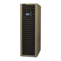
Harris Maxiva ULX-3400 Series Technical Manual (308 pages)
Digital Transmitter
Brand:
Harris
| Category:
Transmitter
| Size: 7 MB
Table of Contents
Table of Contents
15
Purpose of this Manual
19
General Description
20
Maxiva COFDM Series Transmitter Models
22
System Block Diagram
22
Transmitter Control System
23
Transmitter RF Power Control
25
Graphical User Interface
25
Control System Communications
25
Software Updates
26
Remote Control
26
PA Module
26
Module Control
30
Transmitter Power Supplies
31
Cooling System
31
Cooling System Control Panel
33
Pump Module/Heat Exchanger
36
Heat Exchanger Fan Control
37
Pump Operation/Control Logic
37
PA Module and Combiner Cold Plates
38
M2X Multimedia Exciter
40
General Specifications
41
Installation
43
Introduction
43
Documentation
43
Installation Drawings
44
Installation Steps
47
Transmitter Cabinet Placement
48
Cooling System Installation
48
Heat Exchanger and Pump Module Installation
49
Calculation of Cooling System Capacities
51
Rigging Heat Exchanger & Pump Module
53
Initial Inspection
53
Module
53
Liquid Cooling System Plumbing Installation
56
Pump Module & Heat Exchanger Electrical
58
Transmitter AC Connection
62
Safety Ground
63
AC Connections Procedure
64
Checking AC Configuration
66
TB1 TB2 Jumpers 1 Cabinet 10 -16 Modules
66
TB1 TB2 Jumpers 1 Cabinet 1 - 8 Modules
66
Signal and Ground Connections
71
Intercabinet Connections
74
External Interlock Connections
74
Interlock Connector on Customer I/O Panel
74
Fault-Off Interlocks (Safety Interlocks)
74
RF Mute External Interlock Connections (J2)
75
Port Patch Panel Connections
76
Initial Cooling System Turn on
76
Heat Exchanger & Pump Module Start-Up and Maintenance
78
Starting Pumps & Checking Pump Rotation
80
Starting Fans & Checking Fan Rotation
82
Initial System Leak Tests
83
Initial System Cleaning
84
System Flushing
85
Final Cooling System Fill
86
Install PA Modules
87
Initial Turn-On
89
Final Cooling System Turn on
92
Setting the Transmitter Flow Rate
93
Heat Exchanger Fan Turn on Temperatures
94
Verify Pump Switching (Dual Pumps Only)
94
Normal Pump and Fan Operation
95
Operational Pressure Values (Typical)
95
Setting Exciter Parameters
96
RF Initial Turn on
96
Individual Transmitter Parallel Remote Control
99
Connections
99
Individual Transmitter Commands
100
Individual Transmitter Outputs J6, J7& J
101
Individual Transmitter Metering, J9
104
External RF Switch
104
Install Battery in TCU PCM Card
105
Operation
107
Introduction
107
Transmitter Control Panel
107
Hardware Control Buttons
108
Graphical User Interface (GUI)
110
Global Status and Navigation
110
GUI Home Screen
113
Drive Chain Main Menu
115
Drive Chain Faults
116
Drive Chain Meters
117
Power Amp Main Menu
119
PA Faults
120
Output Main Screen
121
Output Faults
122
Power Supply Main Menu
123
PS Faults
124
System Main Menu
125
System Faults
126
System Fault Log
126
System Service
128
Admin Setup (Local GUI Only)
129
System Setup
131
Cabinet Setup
133
System and Cabinet Power Calibrate
133
System Version Screen
134
System Network Screen
134
GUI Menu Structures
135
Theory of Operation
137
Introduction
137
Active Logic Symbols
137
Block Diagram Descriptions
138
AC Distribution
139
Transmitter Control System
140
Graphical User Interface (GUI)
140
Transmitter RF Power Control
141
TCU Control
143
MCM Card
144
PCM Card
145
RF Detector/Pump Control/Interlocks Card
146
PA Interface Card
149
Predriver and IPA Drive a and B Busses
149
PA BP (Backplane) Busses 1 through 4
150
Customer I/O Card
151
Exciter Switcher Card
152
PS Monitor Card
154
Life Support Functions
158
Controller Area Network (CAN) Bus
160
System Bus
161
Cabinet Bus
162
Parallel Control Lines
163
Customer I/O Board
164
Transmitter RF System
165
Apex M2X Exciter(S)
165
Predriver
165
IPA (Driver) and PA Module
169
AC Distribution Board
171
AC/DC Converter Interface Board
171
PA PS (AC/DC) Voltage Select Path
172
PA Monitor Board
174
J1 - PA or IPA Connector I/O Board
175
Signal Distribution Board
177
PA Module Phase Alignment
177
PA Module Splitter
177
PA Module Pallet Combiner
177
RF Pallets
178
FET Bias
179
Module Combiner
179
Cooling System
180
Heat Exchanger/Pump Module Diagrams
180
Leak Detector and Cabinet Drains
184
Maxiva 16 Module Transmitter Diagrams
185
RF Block Diagram
185
Maintenance and Alignments
189
Introduction
189
PA Module Removal and Replacement
189
PA Slot Locations
190
PA Module Removal
191
PA Module Installation
192
Operation with Inoperative PA Modules
194
PA Module/Rack Alignment
194
PA Module Bias
197
PA Module Phasing
197
PA Module Component ID
197
PA and IPA (Driver) Pallet Replacement
199
PA Module AC/DC Converter (PS) Board
201
PS Board Removal and Replacement
201
AC/DC Converter (PS) Board Output Voltage
202
Setting Voltage
202
Power Calibrations
203
Forward Power Calibration
203
Calibrate Forward Total Power
204
Calibrate Forward Cabinet Power
206
Reflected Power Calibrate
206
Calibrate Reflected Total Power
207
Calibrate Reflected Cabinet Power
208
Exciter Output Calibration
209
PDU Calibration
209
Threshold Settings
210
Exciter a & B Threshold Settings
211
Cabinet Reject Load Thresholds
212
System Reflected Thresholds
212
System Foldback Power
212
FWD Pwr Warn
212
Fwd Pwr Flt
212
PA Cabinet Fan Replacement
213
Cabinet Fan Removal
213
PA Cabinet RF System Removal
215
RF System Removal
215
Miscellaneous Maintenance
222
Cooling System Checks
222
Heat Exchanger Cleaning
222
Alternate Pumps
222
Pump Module Strainer Cleaning
222
Coolant Level Management
224
Cooling System Maintenance Notes
225
Coolant Checks
225
Changing Pumps
225
Pump Module Operation Without
226
Transmitter
226
Air Filter Replacement
226
LCD Screen Adjustments
227
LCD Screen Contrast
227
Touch Screen Calibration
227
Date and Time Settings
228
Changing the Battery on the PCM Card
228
PCM Battery Installation Instructions
229
TCU Card Replacement
233
MCM Card Replacement
234
Typical Test Equipment
235
Introduction
237
GUI System Log
238
Maxiva Three-Strike Fault Actions
239
Reflected Power Faults
239
Module Faults
240
Fault Tables
241
Parts List
251
Replaceable Parts List
251
Heat Exchanger/Pump Module Replacement Parts
263
Appendix-A
267
Cutting & Soldering Transmission Line
267
Appendix-B
277
Cooling System Help
277
Appendix-C
297
Grounding Considerations, Surge & Lightning Protection
297
Appendix-D
301
Lightning Protection Recommendation
301
Advertisement
Advertisement
Related Products
Harris Maxiva ULX-1100 Series
Harris Maxiva ULX-1700 Series
Harris Maxiva ULX-2300 Series
Harris Maxiva ULX-5500 Series
Harris Maxiva ULX-8700 Series
Harris Maxiva ULX-9500 Series
Harris Maxiva ULX-12600 Series
Harris Maxiva ULX-17400 Series
Harris Maxiva ULX-18900 Series
Harris Maxiva ULX-26100 Series
Harris Categories
Transmitter
Amplifier
Radio
Receiver
Test Equipment
More Harris Manuals
Login
Sign In
OR
Sign in with Facebook
Sign in with Google
Upload manual
Upload from disk
Upload from URL