Table of Contents
Advertisement
TECHNICAL MANUAL
888-2629-200
Maxiva ULX COFDM Series
Digital Transmitter
Maxiva ULX COFDM
Series Digital Transmitter
This manual applies to the following modulation types:
DVB-T/H
ISDB-T/H
FLO
CTTB
CMMB
Oct. 5, 2010
T.M. No. 888-2629-200
Rev: B
© Copyright Harris Corporation 2010
All rights reserved
Advertisement
Table of Contents

Related Manuals for Harris Maxiva ULX COFDM Series


Summary of Contents for Harris Maxiva ULX COFDM Series
- Page 1 TECHNICAL MANUAL 888-2629-200 Maxiva ULX COFDM Series Digital Transmitter Maxiva ULX COFDM Series Digital Transmitter This manual applies to the following modulation types: DVB-T/H ISDB-T/H CTTB CMMB Oct. 5, 2010 T.M. No. 888-2629-200 Rev: B © Copyright Harris Corporation 2010...
- Page 2 888-2629-200 10/6/10 WARNING: Disconnect primary power prior to servicing.
- Page 3 Replaceable Parts Service Replacement parts are available from HARRIS Service Parts Department 7:00 AM to 7:00 PM Central Time, Monday through Friday, and 8:00 AM to 1:00 PM Central Time on Saturday.
- Page 4 888-2629-200 10/6/10 WARNING: Disconnect primary power prior to servicing.
- Page 5 Manual Revision History Maxiva ULX COFDM Series Digital Transmitter Manual REV. DATE Pages Affected 2010 Mar 15 Created 2010 Oct 5 59529 Update multiple sections. Corrected PS numbering in Sec. 5 10/6/10 888-2629-200 MRH-1 WARNING: Disconnect primary power prior to servicing.
- Page 6 MRH-2 888-2629-200 10/6/10 WARNING: Disconnect primary power prior to servicing.
- Page 7 • In the ten digit part numbers, if the last three numbers are 000, the item is a part that Harris has pur- chased and has not manufactured or modified. If the last three numbers are other than 000, the item is either manufactured by Harris or is purchased from a vendor and modified for use in the Harris product.
- Page 8 viii 888-2629-200 10/6/10 WARNING: Disconnect primary power prior to servicing.
- Page 9 10/6/10 888-2629-200 WARNING: Disconnect primary power prior to servicing.
- Page 10 888-2629-200 10/6/10 WARNING: Disconnect primary power prior to servicing.
- Page 11 The installation, operation, maintenance and service of this equipment involves risks both to personnel and equipment, and must be performed only by qualified personnel exercising due care. HARRIS CORPORATION shall not be responsible for injury or damage resulting from improper procedures or from the use of improperly trained or inexperienced personnel performing such tasks.
- Page 12 888-2629-200 10/6/10 WARNING: Disconnect primary power prior to servicing.
- Page 13 FIRST-AID Personnel engaged in the installation, operation, maintenance or servicing of this equipment are urged to become familiar with first-aid theory and practices. The following information is not intended to be complete first-aid procedures, it is a brief and is only to be used as a reference.
- Page 14 888-2629-200 10/6/10 WARNING: Disconnect primary power prior to servicing.
-
Page 15: Table Of Contents
Table of Contents Section 1 AC Connections Procedure ....2-22 Checking AC Configuration....2-24 Introduction TB1 TB2 Jumpers 1 Cabinet 10 -16 Modules .2-24 TB1 TB2 Jumpers 1 Cabinet 1 - 8 Modules . - Page 16 Table of Contents (Continued) Graphical User Interface (GUI) ....3-4 Device) ....... 4-22 Global Status and Navigation .
- Page 17 Table of Contents Section 6 AC/DC Converter (PS) Board Output Voltage. 5-14 Setting Voltage: ..... . . 5-14 Diagnostics Power Calibrations ..... . . 5-15 Forward Power Calibration .
- Page 18 Table of Contents (Continued)
-
Page 19: Purpose Of This Manual
Maxiva ULX COFDM Series Section 1 Introduction Purpose of This Manual This technical manual contains the information pertaining to the Maxiva ULX Series, solid-state, UHF, COFDM digital TV transmitter. The various sections of this technical manual provide the following types of information. -
Page 20: General Description
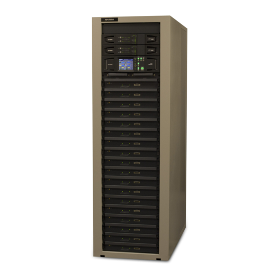
Maxiva ULX COFDM Series Section 1 Introduction General Description This section contains a general description of the Maxiva ULX Series COFDM digital television transmitters. Included in this section will be descriptions of the control system, power amplifier, block diagrams of the different models and system specifications. - Page 21 Section 1 Introduction Maxiva ULX COFDM Series Control Breakers Main Breakers Coolant Hoses In/Out RF Output Line Upper 8 Way Combiner Upper 8 Way Splitter Final Reject Load 3dB Combiner Redundant Cabinet Lower 8 Way Combiner Blowers (2) Lower 8 Way Splitter...
-
Page 22: Maxiva Cofdm Series Transmitter Models
Maxiva ULX COFDM Series Section 1 Introduction 1.2.1 Maxiva COFDM Series Transmitter Models The Maxiva ULX Series COFDM transmitter is available in 13 liquid cooled power levels. The models are listed below in Table 1-1. The last two letters in the transmitter model number, indicate modulation types. For simplicity, the model numbers noted in this maual will be noted as ULX-0000**. -
Page 23: Transmitter Control System
Section 1 Introduction Maxiva ULX COFDM Series modules, 2 driver modules and 16 PA modules. Note that the predriver and driver modules are redundant. 16 PA’s Ethernet Remote / Monitoring Pre-Drivers Driver-PAs TO OTHER System /CAN Bus CABINETS N+1 CAN Bus... - Page 24 Maxiva ULX COFDM Series Section 1 Introduction with the master TCU (in cabinet 1) are interrupted the cabinet bus allows each cabinet to operate independently. The heart of the control system is the TCU which is responsible for control, monitoring and protection.
-
Page 25: Transmitter Rf Power Control
Section 1 Introduction Maxiva ULX COFDM Series first PA cabinet will assume the role of master controller for the system. The TCU’s in the remaining PA cabinets will be slaves. 1.2.4 Transmitter RF Power Control The PA modules operate in open loop mode (no gain or level adjustment). The transmitter RF power control is done via the Phase and Gain Board located in the predriver modules. -
Page 26: Software Updates
NOTE: Software does not need to be loaded into the transmitter unless new components are installed or an update is sent from Harris. The transmitter, as shipped from the factory, is preloaded and ready to run. 1.2.5.2... - Page 27 Section 1 Introduction Maxiva ULX COFDM Series to achieve the various power levels shown in Table 1-1 page1-4. A simplified block diagram of the PA module is shown in Figure 1-5 on page 1-9. The amplifier and driver modules are interchangeable and do not contain microcontrollers but instead use a CPLD based monitor board in each PA to report faults to the TCU and to take appropriate self-protective action if needed.
- Page 28 RF power levels and internal temperatures. The diagnostic port can also be used to reprogram the CPLD as required. The part number for the handheld diagnostics unit kit is 971-0040-081. The Harris part number for the diagnostics unit technical manual is 888-2765-001.
- Page 29 Section 1 Introduction Maxiva ULX COFDM Series Coolant Coolant In/Out RF Out Figure 1-7 Maxiva ULX PA Module (top view, cover removed) Each PA module consists of the following components: a. Monitor Board - Responsible for all monitoring and protection of the module.
-
Page 30: Module Control
Maxiva ULX COFDM Series Section 1 Introduction e. Splitter Board - The splitter board equally divides the RF signal between four (4) power amplifier pallets. The splitter is broadband (covers TV band IV/V). The splitter board also delivers a detected RF sample to the monitor board to indicate input power level and provide protection from excessive input drive power. -
Page 31: Transmitter Power Supplies
Section 1 Introduction Maxiva ULX COFDM Series 1.2.7 Transmitter Power Supplies Three phase AC mains must be supplied to the cabinets via circuit breaker CB23 and CB24 on the AC mains input assembly (A15). The transmitter can accept 208-240VAC (Delta or WYE) or 380-415VAC (WYE) by changing jumpers in three areas: •... - Page 32 Maxiva ULX COFDM Series Section 1 Introduction d. Supply and return line hose and fittings. e. PCI (pump control interface) located in the TCU f. Transmitter PA Module, Splitter and Combiner Cold Plates The liquid cooling system is an efficient closed loop, pressurized system. Prior to operation the cooling system must be properly prepared for operation and bled to remove trapped air.
-
Page 33: Cooling System Control Panel
Section 1 Introduction Maxiva ULX COFDM Series 1.2.8.1 Cooling System Control Panel The cooling system control panel controls the operation of the pump module/heat exchanger, and sends fault and status information to the TCU. The cooling system control connects to the RF Detector/Pump Control/Interlocks card in the TCU for monitoring and control. - Page 34 Maxiva ULX COFDM Series Section 1 Introduction AC Isolator ON/OFF Pump A or B Run LEDs FAN A or B Pump A or B Run LEDs Run LEDs Selected LEDs Controller Set Temp. Set Point Pump & Hyserisis & Hyserisis...
- Page 35 Section 1 Introduction Maxiva ULX COFDM Series h. PUMP - B RUN (ON = Green) i. FAN - A RUN (ON = Green) j. FAN - B RUN (ON = Green) k. PUMP - A SELECTED (ON = Green) l. PUMP - B SELECTED (ON = Green) m.
-
Page 36: Pump Module/Heat Exchanger
Maxiva ULX COFDM Series Section 1 Introduction 1.2.8.2 Pump Module/Heat Exchanger The control panel/pump module and heat exchanger are separate units (each in a rack). The control panel and pump module are self-contained in one rack and include a PID (programmable logic controller), an expansion tank, air purger, pressure gauges, a strainer and optional dual pumps operating in main/standby mode. -
Page 37: Heat Exchanger Fan Control
Section 1 Introduction Maxiva ULX COFDM Series Figure 1-11 Heat Exchanger (before installation) NOTE: The heat exchanger shown in Figure 1-11 is a 2 fan unit. It is shown on a shipping pallet. The two fans that are shown pull air up through the cooling coil/fins (not visible in the photo) of the unit if mounted horizontally (as shown). -
Page 38: Pa Module And Combiner Cold Plates
Maxiva ULX COFDM Series Section 1 Introduction more than 5 seconds in an active pump will cause activation of the standby pump. Loss of flow for more than 15 seconds will cause both pumps to shut down. 1.2.8.3 PA Module and Combiner Cold Plates Each PA Module has a liquid cooled cold plate which connects to the cooling system with quick release connectors. - Page 39 Section 1 Introduction Maxiva ULX COFDM Series Figure 1-12 ULX 8700** Liquid Cooling System (Internal) 10/6/10 888-2629-200 1-21 WARNING: Disconnect primary power prior to servicing.
-
Page 40: M2X Multimedia Exciter
Maxiva ULX COFDM Series Section 1 Introduction 1.2.9 M2X Multimedia Exciter The M2X exciter is used with the Maxiva ULX Series transmitter. This exciter is described in a separate instruction book. A second hot standby exciter, and drive chain switcher is available as an option. The exciter is controlled by the transmitter using an internal CAN bus or Ethernet connection. -
Page 41: General Specifications
Section 1 Introduction Maxiva ULX COFDM Series General Specifications NOTE: Specifications subject to change without notice. Unless otherwise noted specifi- cations apply at the output of the Harris supplied mask filter. Specifications continue on following page. 10/6/10 888-2629-200 1-23 WARNING: Disconnect primary power prior to servicing. - Page 42 Maxiva ULX COFDM Series Section 1 Introduction End of specifications. 1-24 888-2629-200 10/6/10 WARNING: Disconnect primary power prior to servicing.
-
Page 43: Installation
Maxiva ULX COFDM Series Section 2 Installation Introduction This section includes the information necessary for installation and initial turn on of a Maxiva ULX Series solid state, UHF TV transmitter. Due to the modular nature of the Maxiva, all models have similar installation and testing procedures. -
Page 44: Installation Drawings
Maxiva ULX COFDM Series Section 2 Installation The following is a list of documentation that ships with the transmitter. Find and save all documentation. The top level Document Package numbers for each transmitter model are shown below: • ULX-1100**, ULX-1700** ULX-2300**, ULX-3400**, ULX-4400**, ULX- 5500**, ULX-6500**, ULX-8700**: 988-2629-200 •... - Page 45 Section 2 Installation Maxiva ULX COFDM Series e. Wiring Diagram (Main Cabinet) and Wiring Diagram Additional PA Cabinet (for multi-cabinet models) - Interconnection wiring diagram for all assemblies inside the main transmitter cabinet or additional PA cabinets. f. Intercabinet Wiring Diagram - Indicates the connections between multiple PA cabinets, and jumper ID settings (for the multi-cabinet models).
- Page 46 Maxiva ULX COFDM Series Section 2 Installation System Drawing Notes: 1.) RF System Layout 843-5601-288 is for systems containing up to 4 modules. 843- 5601-281 is for systems containing 6 to 16 modules. 2.) Pump Module/Heat Exchanger Outline 843-5601-289 is for cabinets containing up to 8 modules.
-
Page 47: Installation Steps
Section 2 Installation Maxiva ULX COFDM Series Installation Steps Steps in the installation section are numbered in each section. As each step is completed, the step number can be circled to indicate completion. This provides a quick confidence check at the end of the procedure that no steps were skipped. The primary goal of each step is indicated by bold letters, with the rest of the paragraph being support information. -
Page 48: Transmitter Cabinet Placement
Maxiva ULX COFDM Series Section 2 Installation Transmitter Cabinet Placement The transmitter cabinet should be placed where it will have approximately 1 meter clearance on each side and in the back. The front of the transmitter should have a clearance of at least 1.5 meters to allow access for removal and installation of the PA modules. -
Page 49: Heat Exchanger And Pump Module Installation
Section 2 Installation Maxiva ULX COFDM Series a. Electrical Installation Diagram b. AC Power Flow Diagram c. Cooling System Electrical Diagram d. Liquid Cooling System Layout e. Cooling System Outline f. Appendix B chapter in this manual g. Pump Module/Control Panel & Heat Exchanger manufacturer’s instruction manuals 2.5.1... - Page 50 Maxiva ULX COFDM Series Section 2 Installation CAUTION: FOR VERTICALLY MOUNTED HEAT EXCHANGERS, THERE SHOULD BE NO OBSTRUCTION WITHIN TWO METERS IN FRONT OF THE EXHAUST SIDE OF THE FAN (EXHAUST AIR IS DIRECTED OUT THE SIDE OF THE UNIT) OR WITHIN 1 METER OF THE INTAKE SIDE OF THE FAN.
-
Page 51: Calculation Of Cooling System Capacities
NOTE: If any of these restrictions cannot be met, a site-specific modification may be required. Contact your Harris representative for modifications. All fluid piping practices should be in accordance with local codes. Standard installations will use heavy duty hose for connecting the transmitter to the heat exchanger and pump module but copper field piping using type M, hard drawn copper pipe and sweat joints made with soft silver solder is an acceptable alternative. - Page 52 Maxiva ULX COFDM Series Section 2 Installation The capacities shown in Table 2-3 include all cabinet components such as modules, combiners and splitters. The values do not include the pump module coolant or the main interconnection plumbing lines between the transmitter, pump module, and heat exchanger.
-
Page 53: Rigging Heat Exchanger & Pump Module
Section 2 Installation Maxiva ULX COFDM Series Table 2-5 Line length to Capacity Conversion Factors Nominal Type M Feet to Gallons Feet to Liters Meters to Meters to Copper Tube or Gallons Liters Hose Size 1-1/4 inch (OD hose) 0.064 0.242... - Page 54 Maxiva ULX COFDM Series Section 2 Installation NOTE: It is recommended that the heat exchanger and pump module plumbing be pres- surized to 15 PSI with air or an inert gas (nitrogen), as a leak check prior to rig- ging and/or final placement.
- Page 55 Section 2 Installation Maxiva ULX COFDM Series Check the area on the intake side of the fans. It should be free of dirt, STEP 3 dust and debris. Vertically mounted heat exchangers should have no obstructions within 1 meter on the fan intake side and within 2 meters on the exhaust side.
-
Page 56: Liquid Cooling System Plumbing Installation
Charging the expansion tank is not normally required in the field. The tank is pressurized at the factory prior to shipment. Contact Harris Field Service if you feel there is a need to change the air pressure in the expansion tank. - Page 57 Section 2 Installation Maxiva ULX COFDM Series Install drain valves at each low point in the plumbing system. These STEP 4 drain valves allow the closed loop system to be thoroughly drained of liquid as required for flushing or draining the system.
-
Page 58: Pump Module & Heat Exchanger Electrical
Maxiva ULX COFDM Series Section 2 Installation Charge/Fill Point Figure 2-1 Suggested Charge Point CAUTION: DO NOT PRESSURIZE THE SYSTEM USING THE VALVE ON THE EXPANSION TANK. THIS TANK HAS BEEN PRESSURIZED AT THE FACTORY AND IT SHOULD NOT BE CHANGED. - Page 59 STEP 1 from the pump module control panel to the heat exchanger isolator switches. Install and wire according to the Harris Electrical Schematic Diagram and follow local wiring codes. Install another conduit and route wiring for status and control lines STEP 2 between the pump module and transmitter cabinet.
- Page 60 Maxiva ULX COFDM Series Section 2 Installation Status & Mains Control Mains to Fans Figure 2-2 Pump Module & Heat Exchanger Control Panel Connections Turn OFF the isolator switch on the pump module control panel and STEP 3 the isolator switches on the heat exchanger unit. They will be turned ON later in the procedure to check for wiring problems.
- Page 61 Section 2 Installation Maxiva ULX COFDM Series NOTE: Condensation can occur in the conduits connecting the heat exchanger (outside) and the transmitter (inside). These conduits should be caulked or sealed after the system is tested and operational. Sealing the conduit prevents warm air inside the building from entering the portion of the conduit that is located outside the build- ing.
-
Page 62: Transmitter Ac Connection
Maxiva ULX COFDM Series Section 2 Installation Interlocks Status & Control Figure 2-3 Customer I/O Pump Module and Interlock Connector on Transmitter CAUTION: MAXIVA ULX SERIES TRANSMITTERS WILL NOT SUPPORT A WATER COOLED LOAD USING WATER SUPPLIED BY THE ULX PUMP MODULE. ONLY AIR COOLED TEST LOADS SHOULD BE USED WITH ULX SERIES TRANSMITTERS. -
Page 63: Safety Ground
Section 2 Installation Maxiva ULX COFDM Series NOTE: The Maxiva ULX cabinets can use the following AC Mains configurations assuming the jumpers in the backplanes and AC distribution panels are properly configured at the factory: • 208-240VAC, 3 phase Delta or Wye •... -
Page 64: Ac Connections Procedure
Maxiva ULX COFDM Series Section 2 Installation 2.6.2 AC Connections Procedure CAUTION: WHEN CONNECTED TO A 380-415VAC 3 PHASE WYE POWER CONFIGURATION, NEUTRAL CURRENT CAN BE EQUAL TO OR EXCEED PHASE CURRENTS DUE TO SWITCH MODE POWER SUPPLY HARMONICS. FINAL INSTALLATION SHALL ENSURE NEUTRAL CONDUCTOR IS PROPERLY SIZED AND THAT ALL LOCAL REGULATIONS ARE MET. - Page 65 Section 2 Installation Maxiva ULX COFDM Series Connect the safety ground wire to the stud shown in Figure 2-4. STEP 3 There should be separate safety ground wires for each AC mains input. AC Primary Connections Figure 2-5 AC Connections to Terminal Blocks CB23 & CB24...
-
Page 66: Checking Ac Configuration
Maxiva ULX COFDM Series Section 2 Installation 2.6.3 Checking AC Configuration The voltage specifications on the transmitter ID panel should be compared to the supply voltages to be sure they are compatible. Should questions arise the jumpers in TB1 and... - Page 67 Section 2 Installation Maxiva ULX COFDM Series • Driver and PA backplane boards. On the IPA and PA backplane boards, drawing numbers 801-0222-131 and 801-0222-101 respectively, the jumpers on TB1, TB2, and TB3 are connected between terminals 2 and 3 for 208 to 240 VAC Delta or WYE and connected between terminals 1 and 2 for 380 to 415 VAC Wye connections.
- Page 68 Maxiva ULX COFDM Series Section 2 Installation Jumper Figure 2-6 Photo of MOV & TB1 Figure 2-6 shows an AC distribution panel removed from the transmitter. TB1 in this case is for an amplifier cabinet with 8 modules or less.
- Page 69 Section 2 Installation Maxiva ULX COFDM Series Board Board 1 2 3 4 5 6 7 8 9 10 11 1 2 3 4 5 6 7 8 9 10 11 Ground AC Power AC Power Block Entrance Entrance Top View of Back of PA Cabinet, Jumpered for 208 to 240 VAC Delta or WYE...
- Page 70 Maxiva ULX COFDM Series Section 2 Installation Board 1 2 3 4 5 6 7 8 9 10 11 Ground AC Power AC Power Block Entrance Entrance Top View of Back of PA Cabinet, Jumpered for 208 to 240 VAC Delta or WYE...
-
Page 71: Signal And Ground Connections
Section 2 Installation Maxiva ULX COFDM Series Signal and Ground Connections NOTE: Control and signal wires should never be run in the same conduit with any AC wiring. A separate conduit should be used for control/signal cables. Connect the RF Inputs to the customer I/O panel at the top of the STEP 1 transmitter (see Figure 2-9). - Page 72 Maxiva ULX COFDM Series Section 2 Installation Table 2-7 Customer I/O panel Connections for Exciter A Jack Connector Label SMA - 50Ω GPS (antenna) BNC - 50Ω 1PPS BNC - 50Ω 10 MHZ BNC - 75Ω ASI HP1 BNC - 75Ω...
- Page 73 Section 2 Installation Maxiva ULX COFDM Series Table 2-9 RF Samples Connections on Customer I/O Panel Jack Connector Label N - 50 Ω SYS FWD N - 50 Ω SYS REF N - 50 Ω REJECT 1 N - 50 Ω...
-
Page 74: Intercabinet Connections
Maxiva ULX COFDM Series Section 2 Installation Intercabinet Connections For multi-cabinet transmitter models ULX-12800**, ULX-17000** and ULX- 24600**, the inter cabinet connections will need to be installed next. See Intercabinet Wiring Diagram for reference. External Interlock Connections 2.9.1 Interlock Connector on Customer I/O Panel The interlock connector (12 pin) is located on the customer I/O panel at the top of the transmitter. -
Page 75: Rf Mute External Interlock Connections (J2)
Section 2 Installation Maxiva ULX COFDM Series Table 2-10 J2 Interlock Connector on Customer I/O Board Pin Number Description System Safety Interlock System Safety Interlock Return System RF Mute Interlock System RF Mute Interlock Return Cabinet Safety Interlock Cabinet Safety Interlock Return... -
Page 76: Port Patch Panel Connections
Maxiva ULX COFDM Series Section 2 Installation J2 Interlock Connector The transmitter is shipped from the factory with jumpers in the RF Mute interlock posi- tions on J2 which will allow the transmitter to operate without external interlock con- nected. - Page 77 Section 2 Installation Maxiva ULX COFDM Series Pump operation is automatically controlled using a PID process/termperature controller (PID is short for proportional integral derivative). There are two modes of pump operation, “Local”, and “Remote”. The PID controller interfaces with the transmitter’s “Pump Control Interface”...
-
Page 78: Heat Exchanger & Pump Module Start-Up And Maintenance
Maxiva ULX COFDM Series Section 2 Installation 2.11.1 Heat Exchanger & Pump Module Start-up and Maintenance The electrical installation should have already been completed and should be in accordance with the National Electrical Code and any local codes and regulations. The incoming power supply can be 208 to 240V-3Ph-50 or 60Hz, or 380 to 415V-3Ph-50 or 60Hz. - Page 79 Section 2 Installation Maxiva ULX COFDM Series Close cabinet supply and return line valves. Keep closed until initial STEP 2 leak testing, is completed to keep contaminants out of the combiner and splitter chiller plates. Open cabinet(s) bypass valve(s). The cabinets should remain bypassed STEP 3 until leak testing is complete.
-
Page 80: Starting Pumps & Checking Pump Rotation
Maxiva ULX COFDM Series Section 2 Installation CAUTION: IF FREEZING CONDITIONS EXIST DURING CHECKOUT AND FLUSHING PROCEDURES, THE FLUSHING PROCEDURE AND SUBSEQUENT FILL WITH FINAL GLYCOL/WATER MUST BE FINISHED BEFORE STILL WATER IS ALLOWED TO REMAIN IN HEAT EXCHANGER. IF PROCEDURE CANNOT BE FINISHED, CARE MUST BE TAKEN TO PREVENT WATER FROM FREEZING IN OUTSIDE COOLING SYSTEM EQUIPMENT. - Page 81 Section 2 Installation Maxiva ULX COFDM Series Turn the AC (isolator) switch on the Cooling Control Panel to OFF. STEP 1 AC power from the AC mains at the main breaker is routed to the Pump Module and then to the Heat Exchanger via the AC Isolator switch on the Cooling Control Panel.
-
Page 82: Starting Fans & Checking Fan Rotation
Maxiva ULX COFDM Series Section 2 Installation While the alternate pump is coasting to a stop, verify its rotation.The STEP 7 pump rotation can be verified by noting the direction of fin rotation at the back of the pump relative to the rotation arrow marked on the pump cover. -
Page 83: Initial System Leak Tests
Section 2 Installation Maxiva ULX COFDM Series box. Improper fan rotation can be corrected by changing any two of the phases (inside the control panel) supplying the fan. 2.11.2 Initial System Leak Tests During the leak tests in the following steps, check the static pressure of the cooling system while the pumps are momentarily deenergized. -
Page 84: Initial System Cleaning
Maxiva ULX COFDM Series Section 2 Installation 2.11.3 Initial System Cleaning Once the cooling system has been determined to be free of leaks it will have to be cleaned and flushed before continuing the installation. Create cleansing solution. Using a mixture of distilled water (see... -
Page 85: System Flushing
Section 2 Installation Maxiva ULX COFDM Series Run the system for an additional 20 minutes. Alternate pumps A and STEP 8 B for 10 minutes each. Note flow rate of system. Drain the system. To drain the system open the drain hoses and the STEP 9 system vent valves. -
Page 86: Final Cooling System Fill
Maxiva ULX COFDM Series Section 2 Installation 2.11.5 Final Cooling System Fill CAUTION: THE SYSTEM MUST BE TESTED FOR LEAKS AGAIN ONCE THE REQUIRED 50/50 GLYCOL/WATER MIXTURE HAS FILLED THE ENTIRE SYSTEM. A GLYCOL/WATER MIXTURE WILL EXPOSE SMALL LEAKS WHICH ARE NOT EVIDENT WHEN TESTING FOR LEAKS WITH PURE WATER OR AIR. -
Page 87: Install Pa Modules
Section 2 Installation Maxiva ULX COFDM Series the 50/50 mixture. The hydrometer should be capable of measuring specific gravity in the 1.02 to 1.08 range. Information regarding specific gravity measurement is given in Appendix B. 2.12 Install PA Modules Be sure the PA power supply breakers (in rear of cabinet as shown STEP 1 in Figure 2-11) are in the OFF position. - Page 88 Maxiva ULX COFDM Series Section 2 Installation WARNING: THE PA MODULES ARE LARGE AND RELATIVELY HEAVY, WEIGHING APPROXI- MATELY 26.5KG. (59 LBS) CARE SHOULD BE TAKEN TO AVOID PERSONAL INJURY AND/OR DAMAGE TO THE MODULES. Prior to inserting modules remove all packing surrounding the...
-
Page 89: Initial Turn-On
PERATURE. DO NOT TOUCH THE MODULES WITH BARE HANDS AFTER THE TRANSMITTER HAS BEEN RUNNING. SPECIAL GLOVES CAN BE OBTAINED FROM HARRIS, PART #0990006483 OR GRAINGER ITEM #4JF36. PRIOR TO MODULE REMOVAL TURN OFF THE PA MODULE CIRCUIT BREAKER IN THE REAR OF THE CABINET AND THEN ALLOW THE MODULE TO COOL FOR 30 SECONDS BEFORE REMOVAL FROM THE RACK. - Page 90 Maxiva ULX COFDM Series Section 2 Installation Figure 2-12 Home Page Turn on Exciter circuit breakers CB21 & CB22. STEP 4 Check the TCU Low Voltage power supplies and AC Mains voltages. STEP 5 Press the PS (power supply) button to view the PS screen shown in Figure 2-13.
- Page 91 Section 2 Installation Maxiva ULX COFDM Series Figure 2-13 Power Supply Screen Press the PS FAULTS button to check for power supply faults. There STEP 6 should be no red indications or faults present. If a fault is present, see Section 6, Diagnostics for more information.This screen is shown in...
-
Page 92: Final Cooling System Turn On
Maxiva ULX COFDM Series Section 2 Installation Figure 2-14 PS Faults Screen Customize the transmitter System Setup. STEP 7 SYSTEM>SERVICE>SYSTEM SETUP on the GUI. The System Setup screen displays the settings for Sys Pwr Out, Center Frequency, Modulation Type, AC Line Volt (VAC), Number of exciters, Number of Cabinets and System Setup Entry. -
Page 93: Setting The Transmitter Flow Rate
Section 2 Installation Maxiva ULX COFDM Series 2.14.1 Setting the Transmitter Flow Rate Check the transmitter flow rate. Press SYSTEM>SYSTEM STEP 1 COOLING>COOLING METERS. The first line shows the transmitter flow rate. Adjust the Flow Rate if necessary. Adjust the inlet valve for the... -
Page 94: Heat Exchanger Fan Turn On Temperatures
Maxiva ULX COFDM Series Section 2 Installation NOTE: If the pump is unable to deliver the required flow rate, check for correct wiring of the 3 AC phases. Incorrect wiring of the 3-phase sequence would cause the pumps to operate but with much degraded performance. If this is the case, see "2.11.1.1 Starting Pumps &... -
Page 95: Normal Pump And Fan Operation
Section 2 Installation Maxiva ULX COFDM Series Press pump select button for PUMP A ON then PUMP B ON. The STEP 4 pumps should switch. This is indicated on the TCU GUI screen (pump that is on is colored green) as well as in the Cooling Control Panel status light indicators. -
Page 96: Setting Exciter Parameters
Maxiva ULX COFDM Series Section 2 Installation 2.14.2 Setting Exciter Parameters See M2X Exciter manual to set exciter parameters. NOTE: Exciter A is always factory installed as the upper exciter unit in the exciter con- trol cabinet. The optional exciter B is installed immediately below the top exciter unit (see layout photo Figure 1-1 on page 1-2). - Page 97 Section 2 Installation Maxiva ULX COFDM Series Figure 2-15 Power Amps Screen Figure 2-16 IPA Screen See Figure 2-15 and Figure 2-16. All IPA’s and PA’s should show a STEP 8 green (OK) or yellow (indicating low drive) status indication on the GUI (Power Amps screens).
- Page 98 Maxiva ULX COFDM Series Section 2 Installation Cabinet power will go to this level if TCU set to Auto Figure 2-17 Output Screen Slowly bring up the transmitter power (see Output screen) by STEP 9 pressing the RAISE button on front panel to the nominal value, as indicated by the bar graphs.
-
Page 99: Individual Transmitter Parallel Remote Control
Section 2 Installation Maxiva ULX COFDM Series Press Auto on the TCU. Note that Cab. Fwd. Pwr reference value on STEP 13 output screen now reads cabinet output power. 2.15 Individual Transmitter Parallel Remote Control Connections The customer I/O board is located at the top of the individual transmitter cabinet. Table 2-18 shows the board and also lists the connector names and numbers. -
Page 100: Individual Transmitter Commands
Maxiva ULX COFDM Series Section 2 Installation • J9 - Remote Analog Metering Outputs NOTE: The forward slash (/) in front of a signal name means active low. The signal named "/INPUT 1" for example is activated by bringing that input low. Signal names without the forward slash are considered active high. -
Page 101: Individual Transmitter Outputs J6, J7& J
Section 2 Installation Maxiva ULX COFDM Series Table 2-12 J3, J4 & J5, Customer I/O Board, Remote Control Connectors Connector Function Command Type and and pin # Polarity J4-4 IPA_AUTO_SELECT Pulsed LOW J4-5 IPA_MANUAL_SELECT Pulsed LOW J4-6 GROUND GNDA J4-7... - Page 102 Maxiva ULX COFDM Series Section 2 Installation Table 2-13 J6, J7 & J8 Customer I/O Board, Remote Status Outputs Connector Status Output Status Type and Polarity and pin # J6-1 GROUND J6-2 TRANSMITTER_OFF/ON_STATUS L=ON H=OFF J6-3 EXCITER_A/B_ACTIVE_STATUS L= B ON...
- Page 103 Section 2 Installation Maxiva ULX COFDM Series Table 2-13 J6, J7 & J8 Customer I/O Board, Remote Status Outputs Connector Status Output Status Type and Polarity and pin # J7-9 VSWR FAULT L=FAULT H= OK J7-10 TRANSMITTER_FAULTED_OFF L= FAULT OFF...
-
Page 104: Individual Transmitter Metering, J9
Maxiva ULX COFDM Series Section 2 Installation 2.15.3 Individual Transmitter Metering, J9 Each analog metering output will provide 0 - 4.096Vdc output into a 400 ohm load (where 3Vdc = Full Scale). The connections for J9 are listed in Table 2-14. -
Page 105: Install Battery In Tcu Pcm Card
Section 2 Installation Maxiva ULX COFDM Series Table 2-15 External RF Switch J10 Connection Metered Parameter J9-1 SWITCH_COMMON J9-2 GROUND J9-3 RF_SWITCH_POSITION_A_SELECT J9-4 RF_SWITCH_POSITION_B_SELECT J9-5 GROUND J9-6 RF_SWITCH_STATUS_A J9-7 RF-SWITCH_STATUS_B J9-8 GROUND J9-9 GROUND J9-10 J9-11 J9-12 2.16 Install Battery in TCU PCM Card When the transmitter is ready for operation install the real time clock battery in the TCU PCM card. - Page 106 Maxiva ULX COFDM Series Section 2 Installation 2-64 888-2629-200 10/6/10 WARNING: Disconnect primary power prior to servicing.
-
Page 107: Operation
Maxiva ULX COFDM Series Section 3 Operation Introduction This section gives detailed operational information for the Maxiva ULX Series Solid- State UHF TV transmitter. Information will pertain mostly to the operation and navigation of the TCU graphical user interface (GUI) touchscreen display. -
Page 108: Hardware Control Buttons
Maxiva ULX COFDM Series Section 3 Operation Figure 3-1 Transmitter Control Unit (TCU) NOTE: A similar set of GUI screens is available via web browser with an ethernet net- work connection and the optional eCDi hardware interface. 3.2.1 Hardware Control Buttons... - Page 109 Section 3 Operation Maxiva ULX COFDM Series NOTE: The system control buttons described above will be referred to as hardware con- trol buttons in the following manual text. Figure 3-2 TCU Front Panel Lowered There are two power supply cards located on the left side of the TCU chassis and seven cards in the right side of the TCU.
-
Page 110: Graphical User Interface (Gui)
Maxiva ULX COFDM Series Section 3 Operation required. To reset the TCU, pull down the GUI panel exposing the circuit cards in the TCU chassis as shown in Figure 3-2. The second board from the right is the PCM board. The TCU reset button is located about toward the center of the board and it faces outward toward the user. - Page 111 Section 3 Operation Maxiva ULX COFDM Series System Forward Power Bargraph Transmitter Model Number Forward and Reflected Reflected Power Bargraph Power Outputs 100% Mark - Based on Fault & Operational Nominal Power Output setting Status in System Setup screen Figure 3-3 Global Display Header The second line of the display has operational and status information including: a.
- Page 112 Maxiva ULX COFDM Series Section 3 Operation b. Transmitter Forward power output reading in numerical format (for multiple cabinet transmitters this would be a system power reading and not for a single cabinet). It is important to note that this is the power output after the filter.
-
Page 113: Gui Home Screen
Section 3 Operation Maxiva ULX COFDM Series GUI Home Screen The HOME screen shown in Figure 3-3 is the primary operator screen and the default screen after boot up. The HOME screen contains the most important general operator information such as: a. - Page 114 Maxiva ULX COFDM Series Section 3 Operation The quickest way to access the HOME screen is to press either the HOME button on a main menu screen or the BACK button arrow on a submenu screen followed by a HOME button press on the main menu screen.
-
Page 115: Drive Chain Main Menu
Section 3 Operation Maxiva ULX COFDM Series Drive Chain Main Menu If you press the Drive Chain button on the HOME screen, it will take you to the screen shown in Figure 3-5. The Drive Chain Menu structure is shown in Figure 3-26 on page 3-30. -
Page 116: Drive Chain Faults
Maxiva ULX COFDM Series Section 3 Operation 1. Auto/Manual - Auto should be the standard position for normal operation. Placing it in Manual mode prevents an autoswitch to the alternate drive chain. In AUTO mode, if the on-air exciter drops below 50% of nominal power, or if the on-line exciter experiences a fault, the controller will auto- matically switch to the backup drive chain (if available). -
Page 117: Drive Chain Meters
Section 3 Operation Maxiva ULX COFDM Series To Figure 3-7 To Figure 3-5 Figure 3-6 Drive Chain Faults Screen NOTE: Exciter A is always factory installed as the upper exciter unit. The optional exciter B is installed immediately above the TCU and below the top exciter unit (see layout photo Figure 1-1 on page 1-2). - Page 118 Maxiva ULX COFDM Series Section 3 Operation To Figure 3-6 To Figure 3-5 Figure 3-7 Drive Chain Meters Screen 3-12 888-2629-200 10/6/10 WARNING: Disconnect primary power prior to servicing.
-
Page 119: Power Amp Main Menu
Section 3 Operation Maxiva ULX COFDM Series Power Amp Main Menu If you press the Power Amps button on the HOME screen, it will take you to the screen shown in Figure 3-8. The Power Amps Menu structure is shown in Figure 3-26 on page 3-30. -
Page 120: Pa Faults
Maxiva ULX COFDM Series Section 3 Operation NOTE: Always be sure that you are accessing the desired cabinet number. The cabinet being viewed is indicated in the upper left corner of the screen. To get detailed information on a particular PA Module, press the Faults button on the right section of the screen. -
Page 121: Output Main Screen
Section 3 Operation Maxiva ULX COFDM Series Output Main Screen If you press the Output button on the HOME screen, it will take you to the screen shown in Figure 3-10. The Output Menu structure is shown in Figure 3-25 on page 3-29. -
Page 122: Output Faults
Maxiva ULX COFDM Series Section 3 Operation NOTE: If the load interlock is open and the transmitter is switched to the "Test Load" position, the transmitter output will be muted. If a test load interlock is not used the appropriate connection on the interlock connector on the customer I/O panel must be jumpered. -
Page 123: Power Supply Main Menu
Section 3 Operation Maxiva ULX COFDM Series Power Supply Main Menu If you press the Power Supply button on the GUI screen it will take you to the screen shown in Figure 3-12. The Power Supply Menu structure is shown in Figure 3-26 on page 3-30. -
Page 124: Ps Faults
Maxiva ULX COFDM Series Section 3 Operation 3.8.1 PS Faults This is the PS (power supply) Faults screen which lists of all of the monitored power supply faults for the AC mains and low voltage power supplies. An active fault will be highlighted in RED, while a warning condition will be highlighted in YELLOW. -
Page 125: System Main Menu
Section 3 Operation Maxiva ULX COFDM Series System Main Menu If you press the System button on the GUI screen, it will take you to the screen shown in Figure 3-14. The System Menu structure is shown in Figure 3-26 on page 3-30. -
Page 126: System Faults
Maxiva ULX COFDM Series Section 3 Operation 3.9.1 System Faults This screen is accessed by pressing the Faults button on the System screen. An active fault condition is highlighted in RED while a warning condition is highlighted in YELLOW. For more information on these faults refer to Section 6, Diagnostics. - Page 127 Section 3 Operation Maxiva ULX COFDM Series • Table 6-4, “Output Faults List,” on page 6-10 • Table 6-5, “System Faults List,” on page 6-12 These tables are a quick reference list and in most cases is all that is required for an advanced user to diagnose the problem.
-
Page 128: System Service
Maxiva ULX COFDM Series Section 3 Operation 3.9.3 System Service This screen provides a way to change 3 pieces of information which are then used throughout the GUI. The System Service screen us shown in Figure 3-17 on page 3-22. -
Page 129: Admin Setup (Local Gui Only)
Password: Allows user password entry. There are different login and passwords for local and web browser GUI usage. The default logins and password from the factory are: Local GUI password is harris. Web browser password is harris2009. • Expire: Sets the expiration time for the user access level. - Page 130 Maxiva ULX COFDM Series Section 3 Operation • Reboot: This button will reboot the TCU. The transmitter will stay on the air. Reboot takes about 2 minutes To Figure 3-22 Figure 3-19 System Admin Screen (local) To Figure 3-21 Figure 3-20 System Admin Screen (remote)
-
Page 131: System Setup
Section 3 Operation Maxiva ULX COFDM Series Figure 3-21 System Update Screen (remote) The system update screen allows the user to update the PCM software. Browser for a .tcu file, press load file and then Update Now. CAUTION: THE TRANSMITTER WILL BRIEFLY GO OFF AIR WHEN THE SOFTWARE IS UPDATED. - Page 132 Maxiva ULX COFDM Series Section 3 Operation • Modulation Type: Select the system modulation type from the values displayed in the box. • AC Line Volt (VAC): Set this to the nominal AC line voltage at the transmitter site. •...
-
Page 133: Cabinet Setup
Section 3 Operation Maxiva ULX COFDM Series 3.9.3.3 Cabinet Setup • Cab Pwr Out (W): Set cabinet output power here. This is the power out of the cabi- net before the combiner or filter. This needs to be set for each cabinet. Sets cabinet nominal power used to set ALC level. -
Page 134: System Version Screen
Maxiva ULX COFDM Series Section 3 Operation 3.9.3.5 System Version Screen This screen shows the software revision for the TCU controllers. This information should be known before calling for technical support. To Figure 3-17 Figure 3-24 System Version Screen 3.9.3.6 System Network Screen This screen provides information about network settings. -
Page 135: Gui Menu Structures
Section 3 Operation Maxiva ULX COFDM Series To Figure 3-17 Figure 3-25 System Network Screen The System Network screen when viewed from the local GUI has an additional button called Save & Restart Network. When a change is made to one of the network parameters (IP address, mask, etc.) the networking system has to be restarted before the... - Page 136 Maxiva ULX COFDM Series Section 3 Operation Faults Drive Chain Meters Power Meters Amps Output Faults Power Faults Supply Faults Faults Clear Cabinet System Logs Setup Cabinet Calibrate System Calibrate Setup Trips Save Service Version Setup Network Figure 3-26 GUI Menu Tree...
-
Page 137: Theory Of Operation
Maxiva ULX COFDM Series Section 4 Theory of Operation Introduction This section contains detailed descriptions of the Maxiva ULX Series transmitter, its internal sub-assemblies and any pertinent information regarding the external assemblies such as the pump module and heat exchanger. -
Page 138: Block Diagram Descriptions
2300 stands for 2300 watts average power at the transmitter output before the band pass filter. • ** stands for the type of modulation. See Table 2-1 on page 2-1 Table 4-1 Maxiva ULX COFDM Series Transmitter Models Tx Models Cabinets PA Modules Output Power... -
Page 139: Ac Distribution
Section 4 Theory of Operation Maxiva ULX COFDM Series 16 PA’s Ethernet Remote / Monitoring Pre-Drivers Driver-PAs TO OTHER System /CAN Bus CABINETS N+1 CAN Bus TO N+1 CONTROLLER Exciter CAN Bus ÷ Ethernet Ethernet COUPLER EX 1 CAN Bus... -
Page 140: Transmitter Control System
Maxiva ULX COFDM Series Section 4 Theory of Operation • A neutral connection is required, from the AC service entrance to CB23 and CB24 (if used) for the 380 to 415 volt WYE connection, but no neutral connection is required for the 208 to 240 volt Delta or WYE connections. -
Page 141: Transmitter Rf Power Control
Section 4 Theory of Operation Maxiva ULX COFDM Series Operation. The GUI screen is present only in the main TCU (cabinet 1 in multi cabinet systems). 4.4.2 Transmitter RF Power Control The IPA and PA modules have no gain adjustment. The transmitter RF output power is controlled via the Phase and Gain Board located in the Predriver modules. - Page 142 Maxiva ULX COFDM Series Section 4 Theory of Operation Analog television requires an additional, faster version of ALC to correct for sync compression/expansion effects versus average picture level. This fast ALC loop is independent of the TCU and is handled exclusively in the analog domain. The down...
-
Page 143: Tcu Control
Section 4 Theory of Operation Maxiva ULX COFDM Series 4.4.3 TCU Control The heart of the Maxiva control system is the TCU (transmitter control unit). Each cabinet contains a TCU. The main cabinet (cabinet 1 in multi cabinet systems) contains an enhanced TCU (with a GUI screen), while additional PA cabinets contain a basic TCU (without GUI screen). -
Page 144: Mcm Card
Maxiva ULX COFDM Series Section 4 Theory of Operation 4.4.3.1 MCM Card Each TCU contains an MCM (master controller module) card. The MCM is a microprocessor based controller used for all critical transmitter control functions. The MCM cards in each cabinet TCU (in multi cabinet systems) are tied together via the system bus. -
Page 145: Pcm Card
The TCU in each cabinet also contains a PCM (processor control module) card. The PCM card contains the Harris Coldfire based micro module running embedded Linux OS. The PCM allows use of an optional 5.25" color 1/4 VGA GUI touch screen for enhanced monitoring and control. -
Page 146: Rf Detector/Pump Control/Interlocks Card
Maxiva ULX COFDM Series Section 4 Theory of Operation 4.4.3.3 RF Detector/Pump Control/Interlocks Card The RF detector/pump control/interlocks card is located in the TCU. It is made up of a main and daughter board. The card contains seven RMS detectors with adjustable trips set by EPOTS (electronic potentiometers). - Page 147 Section 4 Theory of Operation Maxiva ULX COFDM Series Table 4-2 RF Detector/Pump Control/ Interlocks Card Connector J3 Pinout Signal Description CABINET_SAFETY_INTLK Input - Active high, cabinet safety interlock CABINET_RF_MUTE_INTLK Input - Active high, cabinet RF mute interlock SYSTEM_SAFETY_INTLK Input - Active high, system safety interlock...
- Page 148 Maxiva ULX COFDM Series Section 4 Theory of Operation The RF detector inputs on the back of the RF Detector/Pump Control/Interlocks card are given in Table 4-3. Table 4-3 Detector Inputs on RF Detector/Pump Control/Interlocks Card Signal Description CAB FWD Cabinet forward sample from directional coupler DC1 at combiner output.
-
Page 149: Pa Interface Card
Section 4 Theory of Operation Maxiva ULX COFDM Series 4.4.3.4 PA Interface Card The PA interface card(s) connects the TCU, Predriver assembly, IPA (driver) and PA backplane boards. The interface features 40 digital outputs/inputs and 24 analog outputs/inputs. A fully populated cabinet will require two PA interface cards, one card per eight PA modules. -
Page 150: Pa Bp (Backplane) Busses 1 Through 4
Maxiva ULX COFDM Series Section 4 Theory of Operation board A4A7 to connectors on the predriver assembly and the IPA backplane board, see Figure 4-6. Table 4-4 provides the connections for these busses. Table 4-4 Predriver and IPA Drive A and Drive B Control Busses... -
Page 151: Customer I/O Card
Section 4 Theory of Operation Maxiva ULX COFDM Series Table 4-5 PA Backplane Board BP 1 through BP 4 Control Busses Pin Function Pin Function Pin Function Pin Function 14 PA 3 Fault 3 27 Digital Output 5 40 Gnd... -
Page 152: Exciter Switcher Card
Maxiva ULX COFDM Series Section 4 Theory of Operation 4.4.3.6 Exciter Switcher Card The exciter switcher card in the main cabinet TCU controls exciter switching with a board mounted relay. It includes 2 RMS detectors with adjustable trip points that use EPOT’s to monitor exciter power. - Page 153 Section 4 Theory of Operation Maxiva ULX COFDM Series Table 4-6 Exciter A Control/Status Connector J1A on TCU (9 pin female dsub) Signal Description /EXC_A_MUTE_CMD Open collector output- Exciter A mute command-100mA sink capability @ 0.8Vdc max. 1K ohm pull up to +5V. TVS protection.
-
Page 154: Ps Monitor Card
Maxiva ULX COFDM Series Section 4 Theory of Operation Table 4-7 Exciter B Control/Status Connector J1B on TCU (9 pin female dsub) Signal Description /EXC_B_MUTE_CMD Open collector output- Exciter B mute command-100mA sink capability @ 0.8Vdc max. 1K ohm pull up to +5V. TVS protection. - Page 155 Section 4 Theory of Operation Maxiva ULX COFDM Series Figure 4-8 PS Monitor Card Block Diagram 10/6/10 888-2629-200 4-19 WARNING: Disconnect primary power prior to servicing.
- Page 156 Maxiva ULX COFDM Series Section 4 Theory of Operation Table 4-8 AC1 MOV1 Connector J4A (25 pin stacked female dsub) Signal Description /MOV_SENSE CMOS input -MOV board sense status-’0’ on this line indicates the MOV board is present. TVS protection. 1K pull up to +5Vdc +15Vdc +15Vdc @ 200mA maximum limited by 0.2A...
- Page 157 Section 4 Theory of Operation Maxiva ULX COFDM Series Table 4-9 AC2 MOV2 Connector J4B (25 pin stacked female dsub) Signal Description /MOV_SENSE CMOS input -MOV board sense status-’0’ on this line indicates the MOV board is present. TVS protection. 1K pull up to +5Vdc +15Vdc +15Vdc @ 200mA maximum limited by 0.2A...
-
Page 158: Life Support Functions
Maxiva ULX COFDM Series Section 4 Theory of Operation 4.4.4 CPLD (Complex Programmable Logic Device) Each PA (power amplifier) module contains a CPLD (Complex Programmable Logic Device) device. The CPLD is not a microprocessor but is a pre-programmed discrete logic device and therefore very stable and reliable. The CPLD’s in the PA modules are responsible for reporting faults back the TCU and also for taking action when the ON/ STBY command is issued by the TCU. - Page 159 Section 4 Theory of Operation Maxiva ULX COFDM Series Table 4-10 Life Support Functionality System Function Description Available in Life Support Mode PA Three Strike PA module three strike operation required operational Sequence PCM. Manual Pump Switch Pump switch over controlled by push button from pump Over control card or by parallel remote interface.
-
Page 160: Controller Area Network (Can) Bus
Maxiva ULX COFDM Series Section 4 Theory of Operation Table 4-10 Life Support Functionality System Function Description Available in Life Support Mode Exciter Parallel Control Exciter Serial Communications Web Connectivity 4.4.6 Controller Area Network (CAN) Bus The Controller Area Network or CAN bus is a high speed serial communications link which is used between the transmitter control boards for transmission of control, status, fault and metering information. -
Page 161: System Bus
Section 4 Theory of Operation Maxiva ULX COFDM Series NOTE: The MCM card (in the TCU) contains LED’s that will flicker on and off at a ran- dom rate indicating that there is activity on the CAN bus. If the LED’s are off or always on, then the CAN bus is most likely not communicating. -
Page 162: Cabinet Bus
Maxiva ULX COFDM Series Section 4 Theory of Operation Table 4-11 MCM System Bus Connector Signal Description SYS)_CAN_H CAN (5V) pass-through /CAB_AC_LOW 3.3V CMOS Input /SYS_OFF_CMD 3.3V CMOS I/O /SYS_RF_MUTE 3.3V CMOS I/O SYS_ALC 0-4.095V Analog I/O SYS_PS_ADJUST 0-4.095V Analog I/O /SYS_FAULT_OFF 3.3V CMOS I/O... -
Page 163: Parallel Control Lines
Section 4 Theory of Operation Maxiva ULX COFDM Series Pin 7 of the cabinet bus carries the PA_voltage_select signal from the MCM card to the IPA and PA backplanes. Its function is to set the output voltage of the AC to DC converters in the PA (and IPA) modules. -
Page 164: Customer I/O Board
Maxiva ULX COFDM Series Section 4 Theory of Operation d. /SYS_FLT_OFF This command is initiated whenever a fault occurs that requires all RF to be shut off and the amplifiers to be disabled. This is a latching type signal that requires user input to clear the fault and turn the transmitter back on. -
Page 165: Transmitter Rf System
Section 4 Theory of Operation Maxiva ULX COFDM Series J6 Status 1 see Table 2-13 on page 2-60 for connections J7 Status 2 see Table 2-13 on page 2-60 for connections J8 Status 3 see Table 2-13 on page 2-60 for connections... - Page 166 Maxiva ULX COFDM Series Section 4 Theory of Operation Figure 4-10 Predriver Module Photo (module removed from Predriver assembly) The predriver assembly holds two predriver modules. The modules are redundant and hot swappable. See photo in Figure 4-10 on page 4-30 to aid in identification of predriver module components.
- Page 167 Section 4 Theory of Operation Maxiva ULX COFDM Series Predriver Tray A Interface 28 Volt Interconnect Board Power Board 801-0222-261 Supply 801-0222-271 Filter Connector and Switch Sync Input J3, DC and Control DC and Control Phase & Gain CD2007 Board...
- Page 168 Maxiva ULX COFDM Series Section 4 Theory of Operation The CD2007 output amplifier board and the phase and gain board receive their power form the power supply board mounted on the tray. This power supply produces 28 Vdc at 4.5 amps maximum.
-
Page 169: Ipa (Driver) And Pa Module
Section 4 Theory of Operation Maxiva ULX COFDM Series 4.6.3 IPA (driver) and PA Module The purpose of Maxiva ULX PA and IPA (driver) module is to amplify modulated RF signal providing approximately 19dB gain over the TV frequency bands IV/V. The module includes its own power supply section that generates drain bias for RF power generating section of the module. - Page 170 Maxiva ULX COFDM Series Section 4 Theory of Operation AC Power See Figure 4- 16 for details of connector J! AC Distribution Board A2 801-0222-021 PFE500-48 PFE500-48 PFE500-48 PFE500-48 PFE500-48 PFE500-48 PFE500-48 PFE500-48 PWR Supply PWR Supply PWR Supply PWR Supply...
-
Page 171: Ac Distribution Board
Section 4 Theory of Operation Maxiva ULX COFDM Series 4.6.3.1 AC Distribution Board The AC distribution board consists of three identical groups of AC line filtering, two stages of transient protections per filter section. First stage of the protection is formed by a network of MOVs which connects to the AC line filter inputs. -
Page 172: Pa Ps (Ac/Dc) Voltage Select Path
Maxiva ULX COFDM Series Section 4 Theory of Operation Table 4-14 PS Connector Pin Assignments Signal Description Input, 3.4A, 240VAC fused at 5A Not connected Input, 3.4A, 240VAC fused at 5A Ground Ground DC Trim Input, 6.49K ohms, 0.75VDC to 6.0VDC DC Source Output, 0.4A, 50VDC... - Page 173 Section 4 Theory of Operation Maxiva ULX COFDM Series IPA Backplane Board 801-0222-131 The Bold line represents The IPA Modules are the same as the the Cabinet Bus path. J2-7 J3-B5 PA Modules, therefore, the voltage select signal path is the same as shown J4-B5 for the PA module.
-
Page 174: Pa Monitor Board
Maxiva ULX COFDM Series Section 4 Theory of Operation Figure 4-15 AC/DC Converter Interface Block Diagram 4.6.3.4 PA Monitor Board The PA Monitor Board controls and monitors the PA module’s operation. All analog parameters of the power amplifier are monitored and evaluated via the analog comparators to generate the OK/FAULT logic signal, and the signal is sent to a CPLD device to realize a pre-defined control logic algorithm. -
Page 175: J1 - Pa Or Ipa Connector I/O Board
Section 4 Theory of Operation Maxiva ULX COFDM Series • 2, 010, VSWR Fault • 3, 011, Overdrive Fault • 4, 100, PS Failure • 5, 101, MOSFET Fault • 6, 110, RF IN Low Fault The Monitor board contains the PA module control circuitry. It is a CPLD controlled circuit, which accepts commands from the TCU and returns status and monitoring signals to the TCU. - Page 176 Maxiva ULX COFDM Series Section 4 Theory of Operation The pins of Sections E through L are arranged in dual vertical rows four pins each. All eight pins of each section (E through K) are connected together and used for three phase AC input with the eight pins of section L connected to ground.
-
Page 177: Signal Distribution Board
Section 4 Theory of Operation Maxiva ULX COFDM Series 4.6.3.6 Signal Distribution Board Signal Distribution Board serves to route analog and digital control and monitoring data between 4 other board subassemblies, such as: • Monitor Board • Four PA Pallets •... -
Page 178: Rf Pallets
Maxiva ULX COFDM Series Section 4 Theory of Operation combining of the signals is done in series fashion with the first stage being a 2-way 3dB hybrid, the second stage being a 2-way 4.77dB hybrid, and the 3 stage being a 2-way 6dB hybrid. -
Page 179: Fet Bias
Section 4 Theory of Operation Maxiva ULX COFDM Series 4.6.3.10.1 FET Bias The LDMOS FET’s used in the Maxiva ULX pallets have been designed by the manufacturer to maintain the factory bias characteristics without the need for re-biasing in the field. The idle current for each FET is set at the factory to approximately 1 amp. -
Page 180: Cooling System
Maxiva ULX COFDM Series Section 4 Theory of Operation Cooling System Information about the Maxiva ULX cooling system can be found in 1.2.8 on page 1-13 and in 2.5 on page 2-6. 4.7.1 Heat Exchanger/Pump Module Diagrams Figure 4-18 is a block diagram that shows the major components in the heat exchanger pump module system. - Page 181 Section 4 Theory of Operation Maxiva ULX COFDM Series Figure 4-18 Heat Exchanger/Pump Module Block Diagram 10/6/10 888-2629-200 4-45 WARNING: Disconnect primary power prior to servicing.
- Page 182 Maxiva ULX COFDM Series Section 4 Theory of Operation Figure 4-19 Heat Exchanger/Pump Module Schematic 4-46 888-2629-200 10/6/10 WARNING: Disconnect primary power prior to servicing.
- Page 183 Section 4 Theory of Operation Maxiva ULX COFDM Series Figure 4-20 Heat Exchanger & Pump Module Schematic_Part 1 10/6/10 888-2629-200 4-47 WARNING: Disconnect primary power prior to servicing.
-
Page 184: Leak Detector And Cabinet Drains
Maxiva ULX COFDM Series Section 4 Theory of Operation 4.7.2 Leak Detector and Cabinet Drains A leak detector is installed at the bottom of the cabinet. The leak detector is shown in Figure 4-21 on page 4-48. It is mounted in the bottom cabinet near the center. The leak detector consists of a small reservoir with a float. -
Page 185: Maxiva 16 Module Transmitter Diagrams
Section 4 Theory of Operation Maxiva ULX COFDM Series Maxiva 16 Module Transmitter Diagrams The Maxiva transmitter has many configurations for different power levels. A PA cabinet can hold up to 16 PA modules, and can have up to three cabinets. This paper refers to the 16 module transmitter which is housed in the main PA cabinet. - Page 186 Maxiva ULX COFDM Series Section 4 Theory of Operation • Sync, required for analog TV transmitters only. The outputs from the PA modules are combined as follows: • PA Slots 1 through 8 are combined in 8-Way combiner A13. •...
- Page 187 Section 4 Theory of Operation Maxiva ULX COFDM Series Exciter: RF drive for 2nd 2K unit APEX-M2X RF drive for 3rd 2K unit ATSC Mode IPA Module A 3-Way Splitter, separate manual Exciter 843-5601-012 Predriver SP3, Page 3 of 888-2624-003...
- Page 188 Maxiva ULX COFDM Series Section 4 Theory of Operation 4-52 888-2629-200 10/6/10 WARNING: Disconnect primary power prior to servicing.
-
Page 189: Maintenance And Alignments
AFTER THE TRANSMITTER HAS BEEN RUNNING, ESPECIALLY IN HIGH AMBIENT TEMPERATURE ENVIRONMENTS. SPECIAL GLOVES CAN BE OBTAINED FROM HARRIS, PART #0990006483 OR GRAINGER ITEM #4JF36. BEFORE MODULE REMOVAL ALLOW THE MODULES TO COOL IN THE RACK FOR 30 SECONDS AFTER TURNING THEM OFF WITH THE CIRCUIT BREAKER. -
Page 190: Pa Slot Locations
Maxiva ULX COFDM Series Section 5 Maintenance and Alignments CAUTION: RADIO FREQUENCY HAZARD. DO NOT ATTEMPT TO OPERATE THE PA MODULE WITH THE COVER REMOVED. 5.2.1 PA Slot Locations The number and location of PA modules will vary depending on transmitter model. The following table outlines the slots that contain PA modules in various configurations. -
Page 191: Pa Module Removal
Section 5 Maintenance and Alignments Maxiva ULX COFDM Series 5.2.2 PA Module Removal Apex M2X Exciter A TCU System Controller Apex M2X Exciter B Redundant Pre-Driver A Redundant Pre-Driver B PA Slots 11-18 Redundant Drivers IPA A (slot 10) IPA B (slot 9) -
Page 192: Pa Module Installation
Maxiva ULX COFDM Series Section 5 Maintenance and Alignments Prepare a clear path to a location to put the module once it has been STEP 1 removed. Open the rear door. STEP 2 Turn off corresponding PA module circuit breaker on the left rear STEP 3 side of the cabinet. - Page 193 Section 5 Maintenance and Alignments Maxiva ULX COFDM Series Push evenly on the front of front of the module with a slight side to STEP 5 side motion to help align the mating connectors. Use firm, moderate pressure to fully seat the module. If the module...
-
Page 194: Operation With Inoperative Pa Modules
Maxiva ULX COFDM Series Section 5 Maintenance and Alignments 5.2.4 Operation With Inoperative PA Modules The PA module reject loads, located inside the module combiner, are sized with enough margin to allow operation under any imbalance condition that may be encountered. As long as one module is installed and operational the transmitter will continue to produce RF power but at reduced levels (depending on how many modules are removed). - Page 195 Section 5 Maintenance and Alignments Maxiva ULX COFDM Series Upper Manifold Clamps Manifold Interconnect Hoses Lower Manifold Clamps Cabinet Drain Hoses Figure 5-3 PA Module/Rack Alignment Loosen hoses between upper and lower manifolds (If more than 8 STEP 5 PA's).
- Page 196 Maxiva ULX COFDM Series Section 5 Maintenance and Alignments Alignment Shims Using the top and bottom modules in each half as alignment fixtures, STEP 6 place a 0.02"-0.03" thick shim on the cabinet PA shelf guides for a top and bottom module. Carefully insert the top and bottom modules...
-
Page 197: Pa Module Bias
Section 5 Maintenance and Alignments Maxiva ULX COFDM Series PA Module Bias Re-bias of the PA modules is not required on the Maxiva ULX series transmitters. PA Module Phasing Phasing of the PA modules is tightly controlled at the factory. No phasing of the modules is required in the field. - Page 198 Maxiva ULX COFDM Series Section 5 Maintenance and Alignments Figure 5-4 gives the power supply and pallet identification numbers.The test connector on the front of the PA module can be used to determine which pallet or power supply has failed. An optional hand held meter can be attached to the connector to display the status and fault information outlined in Table 5-2.
-
Page 199: Pa And Ipa (Driver) Pallet Replacement
Section 5 Maintenance and Alignments Maxiva ULX COFDM Series PA and IPA (driver) Pallet Replacement Jumper Allen Screws (torque) Support Blue & Gray Wires Jumper Figure 5-5 PA Module Pallet (one of four per module) Turn off PA module breaker. - Page 200 Maxiva ULX COFDM Series Section 5 Maintenance and Alignments De-solder two jumpers and the blue & gray DC supply wires. STEP 7 Remove board and cleanup heat transfer compound. STEP 8 NOTE: Removal of the pallet may be difficult due to the presence of the heat transfer compound under the board.
-
Page 201: Pa Module Ac/Dc Converter (Ps) Board
Section 5 Maintenance and Alignments Maxiva ULX COFDM Series PA Module AC/DC Converter (PS) Board 5.7.1 PS Board Removal and Replacement PS Board Trim Connector WAGO Fuse Figure 5-6 PA Module AC/DC Converter (PS power supply) Board NOTE: PS board fuse is 5A 250V fast blow. -
Page 202: Ac/Dc Converter (Ps) Board Output Voltage
Maxiva ULX COFDM Series Section 5 Maintenance and Alignments Install a new heat transfer pad (411-0126-000). STEP 8 Install PS hold down screws. STEP 9 Reconnect supply wire to WAGO. STEP 10 Replace PA module cover. STEP 11 Replace PA module in rack. Tighten module hold down screws. -
Page 203: Power Calibrations
When the transmitter ships from the factory the local GUI default login is "admin" and the default password is "harris" (do not include quotation marks in login or password). If you change passwords be sure to retain them in a secure location. -
Page 204: Calibrate Forward Total Power
Maxiva ULX COFDM Series Section 5 Maintenance and Alignments Forward Couplers Reflected Coupler Figure 5-7 Typical Output Power Coupler 5.8.1.1 Calibrate Forward Total Power a. Calibrate the averaging power meter following manufacturers instructions. b. Set the meter offset to that printed on the coupler, or as supplied with a data sheet included with the Factory Test Data. - Page 205 Section 5 Maintenance and Alignments Maxiva ULX COFDM Series i. Re-adjust the transmitter power output as required to reach licensed nominal power. Be sure it is stable. j. Disconnect the power meter probe form the Forward coupler port then reconnect forward sample cable.
-
Page 206: Calibrate Forward Cabinet Power
Maxiva ULX COFDM Series Section 5 Maintenance and Alignments 5.8.1.2 Calibrate Forward Cabinet Power: a. Repeat the entire above procedure using the internal transmitter Incident (for- ward) sample (shown in Figure 5-9), entering the data in the corresponding PA cabinet window shown in Figure 5-10 on page 5-22. -
Page 207: Calibrate Reflected Total Power
The cabinet fault threshold is set to a VSWR = 1.9:1 at the factory and is not adjustable by the user. A 1.9:1 VSWR corresponds to 9.63% reflected power. NOTE: The cabinet fault threshold is set to 1.9:1 at the factory. Contact Harris service if these values need to be changed. 5.8.2.1 Calibrate Reflected Total Power NOTE: Before attempting reflected calibration Forward calibration must be verified. -
Page 208: Calibrate Reflected Cabinet Power
Maxiva ULX COFDM Series Section 5 Maintenance and Alignments NOTE: The detector level should be approximately 2V when the reflected cable is attached to the forward port with a 10 dB pad. If the reflected detector voltage is too high when attached to the forward port with a 10 dB pad then additional pads must be added to get the voltage in the 2V range. -
Page 209: Exciter Output Calibration
Section 5 Maintenance and Alignments Maxiva ULX COFDM Series 5.8.3 Exciter Output Calibration Turn on the transmitter and adjust to nominal power. STEP 1 With the exciters operating use the web browser to access each STEP 2 exciter and record the output levels for exciters A and B (if present). -
Page 210: Threshold Settings
Maxiva ULX COFDM Series Section 5 Maintenance and Alignments NOTE: This voltage is used as a reference to indicate exciter power output. If too low the transmitter ALC will not adust in Auto. If less than a factory set threshold it assumes there is an exciter issue and disables ALC. -
Page 211: Exciter A & B Threshold Settings
Section 5 Maintenance and Alignments Maxiva ULX COFDM Series Figure 5-11 Threshold Setting Screen 5.8.5.1 Exciter A & B Threshold Settings Exciter A and B detector levels should be approximately 2.7V. This assumes a 100mW (average) out. Exciter A and B threshold levels can be set using the following steps: Set the exciter to nominal output 100 mW (average). -
Page 212: Cabinet Reject Load Thresholds
Maxiva ULX COFDM Series Section 5 Maintenance and Alignments Restore transmitter to normal operating condition and reset the STEP 6 exciter output power to 100 mW. End of procedure. STEP 7 5.8.5.2 Cabinet Reject Load Thresholds Cabinet reject loads should be set to approximately 3V thresholds at 100% reject power levels. -
Page 213: Pa Cabinet Fan Replacement
Section 5 Maintenance and Alignments Maxiva ULX COFDM Series PA Cabinet Fan Replacement There are two 230V AC 50/60Hz fans in the Maxiva cabinet. They get their AC power from the control breakers on power distribution panel. NOTE: Deactivating the control breakers will turn off the cabinet fans but they also will disable the TCU and exciters. - Page 214 Maxiva ULX COFDM Series Section 5 Maintenance and Alignments REMOVE Figure 5-13 Fan Bracket Hardware Fan enclosure can now be removed from the cabinet angling the rear STEP 4 of the unit toward the center of the cabinet and pulling it out through the door opening.
-
Page 215: Pa Cabinet Rf System Removal
Section 5 Maintenance and Alignments Maxiva ULX COFDM Series Fan Capacitor Figure 5-14 Fan Capacitor (inside fan enclosure) Reverse the process to replace the fan. STEP 5 5.10 PA Cabinet RF System Removal Removal of the cabinet RF system is required if access to the PA backplanes, IPA backplanes, combiners or dividers is needed. - Page 216 Maxiva ULX COFDM Series Section 5 Maintenance and Alignments RF Output Coax Clamp Plate Screws 4 places Figure 5-15 RF Output Plate Loosen the clamp on the outer conductor flange coupling that is STEP 6 located the cabinet output directional coupler (see Figure 5-16 on page 5-29).
- Page 217 Section 5 Maintenance and Alignments Maxiva ULX COFDM Series Clamp Figure 5-16 RF Output Coaxial Line Connection Lift the output coax line (the line above the coupler) upward taking STEP 7 care to disconnect and support the inner conductor. Lift the inner and outer upward through the top of the cabinet.
- Page 218 Maxiva ULX COFDM Series Section 5 Maintenance and Alignments Remove Figure 5-17 RF Support Bracket - Lower Use a 13 mm wrench to remove the two bolts from the center of the STEP 10 RF support bracket (see Figure 5-18 on page 5-30).
- Page 219 Section 5 Maintenance and Alignments Maxiva ULX COFDM Series Reject Load Clamp Elbow Figure 5-19 Reject Load Elbow. Remove the sample cables from the directional coupler at the output STEP 11 of the hybrid combiner. While supporting the weight of the hybrid combiner/coax RF system...
- Page 220 Maxiva ULX COFDM Series Section 5 Maintenance and Alignments Clamp Figure 5-20 Upper Combiner Output Clamp Once the clamps on the combiner outputs are loose the hybrid STEP 13 coupler and coaxial assembly can be supported and then pulled away from the module combiners. The hybrid combiner/coaxial RF system can then be removed from the cabinet and stored in a safe location.
- Page 221 Section 5 Maintenance and Alignments Maxiva ULX COFDM Series Figure 5-22 Cabinet with RF System Removed Reverse the procedure to reinstall the cabinet RF system. STEP 14 End of procedure STEP 15 10/6/10 888-2629-200 5-33 WARNING: Disconnect primary power prior to servicing.
-
Page 222: Miscellaneous Maintenance
Maxiva ULX COFDM Series Section 5 Maintenance and Alignments 5.11 Miscellaneous Maintenance 5.11.1 Cooling System Checks Inspect the cooling system weekly for coolant leaks and check the coolant level. 5.11.1.1 Heat Exchanger Cleaning The heat exchanger fins and pump motor housing fins should be examined for dust and dirt buildup once a month. - Page 223 Section 5 Maintenance and Alignments Maxiva ULX COFDM Series initial installation may vary depending on site conditions but in most cases annual inspection and cleaning of the cooling system strainer is recommended. The strainer must be disassembled and cleaned when the transmitter is off the air since the coolant flow must be disrupted prior to opening the strainer assembly.
-
Page 224: Coolant Level Management
Maxiva ULX COFDM Series Section 5 Maintenance and Alignments NOTE: A small amount of liquid will still be present in the pipe and strainer housing, and a receptacle (bucket) will be necessary to contain the spillage. d. Pull strainer screen e. -
Page 225: Cooling System Maintenance Notes
Section 5 Maintenance and Alignments Maxiva ULX COFDM Series 5.11.1.5 Cooling System Maintenance Notes 5.11.1.5.1 Coolant Checks: The pH level of the 50/50 glycol/water mixture should be above 8.0. A PH level that is below 8.0 indicates that the inhibitors in the glycol are ineffective. Should the PH level of the mixture drop below 8.0 either additives must be added or the coolant should be... -
Page 226: Pump Module Operation Without
Maxiva ULX COFDM Series Section 5 Maintenance and Alignments e. Perform the above steps in reverse order to restore the cooling system to normal operation. f. Once system operation is restored check the sight glass to be sure that air bubbles are not present and that the level of coolant is adequate. -
Page 227: Lcd Screen Adjustments
Section 5 Maintenance and Alignments Maxiva ULX COFDM Series Pull lower part of filter through the door opening. STEP 2 Slide the filter assembly downward and away from the door. STEP 3 Figure 5-25 Filter Being Removed from Rear Door g. -
Page 228: Date And Time Settings
5.11.4 Changing the Battery on the PCM Card Transmitter control units (TCU’s) are shipped as components in several different Harris transmitter models. The TCU will contain different printed circuit cards depending on the transmitter application. TCU’s that have GUI (graphical user interface touch screen) displays will contain a PCM card. -
Page 229: Pcm Battery Installation Instructions
Section 5 Maintenance and Alignments Maxiva ULX COFDM Series from the PCM card. The battery should be installed before the transmitter goes into operation. The clock battery (part number 660-0093-000) is packed inside a plastic bag that contains battery replacement instructions. Once the transmitter is installed and AC power has been connected the clock battery should be installed in the PCM card. - Page 230 Maxiva ULX COFDM Series Section 5 Maintenance and Alignments Remove 1 screw from each side to pivot TCU down Figure 5-28 TCU Slide Brackets On Maxiva ULX transmitters the entire TCU unit can be pivoted STEP 3 downward for easier access to the cards. This is done by removing the front screw (shown in figure 5-28) on either side of the TCU slide brackets.
- Page 231 Section 5 Maintenance and Alignments Maxiva ULX COFDM Series Figure 5-29 TCU Pivoted Downward NOTE: In other types of transmitters like LAX and HPX the TCU can’t be pivoted down- ward. In these cases a stool or ladder may be used to gain easier access to the top of the TCU unit.
- Page 232 Maxiva ULX COFDM Series Section 5 Maintenance and Alignments PCM battery holder Figure 5-30 PCM Battery Holder (LAX version of TCU shown) Use a small flat blade screw driver to gently pry open the battery hold STEP 6 down clip while sliding the battery under the clip. The + side of the battery must installed closest to the battery clip (i.e.
-
Page 233: Tcu Card Replacement
Section 5 Maintenance and Alignments Maxiva ULX COFDM Series PCM battery installed Figure 5-31 PCM Card (removed from TCU) with Battery Installed Close front panel. STEP 7 Pivot TCU upward and reinstall the screw on each side of the slide STEP 8 bracket. -
Page 234: Mcm Card Replacement
Maxiva ULX COFDM Series Section 5 Maintenance and Alignments Use the cut outs built into the front of the TCU as handles, pull STEP 3 outward and down on the front cover of the TCU. On Maxiva ULX transmitters the entire TCU unit can be pivoted STEP 4 downward for easier access to the cards. -
Page 235: Typical Test Equipment
Section 5 Maintenance and Alignments Maxiva ULX COFDM Series card need to be replaced the following components should be set to the same values aas the original board. The settings that should be checked are: Blue jumpers: JP-6 JP-7 JP-8 Rotary Switch (Cabinet ID S1): Switch should be set to 1 for cabinet 1, 2 for second cabinet, etc. - Page 236 Maxiva ULX COFDM Series Section 5 Maintenance and Alignments Table 5-3 Recommended Test Equipment Harris Part Equipment Type Manufacturer Model Number Options (if applicable) Frequency Agilent 53131A or 53181A 010 high stability time base measurement 015 range extension to 1.5 GHz, OR 030 range extension to 3.0 GHz...
-
Page 237: Introduction
Maxiva ULX COFDM Series Section 6 Diagnostics Introduction This section contains diagnostic and troubleshooting information for the ULX series UHF transmitter. Included is a complete description of all faults which can be displayed via the transmitter front panel TCU display or GUI (Graphical User Interface). Due to... -
Page 238: Gui System Log
Maxiva ULX COFDM Series Section 6 Diagnostics software buttons along the right side as shown in Figure 6-1, aother option is to start by going to the System Log and seeing what faults have occurred and in what order. If you are not familiar with GUI navigation, refer to Section 3. -
Page 239: Maxiva Three-Strike Fault Actions
Section 6 Diagnostics Maxiva ULX COFDM Series c. BACK - Will take you back to the System main menu. NOTE: Tables 6-1 and 6-2 give a complete listing of all possible faults in the Maxiva transmitter. They also give a brief description of each fault, the trip point and the transmitter action taken in response to the fault. -
Page 240: Module Faults
Maxiva ULX COFDM Series Section 6 Diagnostics 6.3.2 Module Faults Should a module failure occur (say a power glitch) the TCU will initiate a three-strike action. This action will cause a reset of only the PA Module experiencing the fault and not the entire transmitter. -
Page 241: Fault Tables
Section 6 Diagnostics Maxiva ULX COFDM Series Fault Tables The following tables provide a listing of Maxiva Transmitter faults along with a brief description, the fault level or threshold and the action taken by the transmitter. Table 6-1 Maxiva Drive Chain Fault List... - Page 242 Maxiva ULX COFDM Series Section 6 Diagnostics Table 6-1 Maxiva Drive Chain Fault List TYPE Description Fault Level or Transmitter Three Available Threshold Action Strike in Life Support Exciter B Power Exciter B power Trip point is 50% of Exciter Switch...
- Page 243 Section 6 Diagnostics Maxiva ULX COFDM Series Table 6-2 PA and IPA Module Fault List TYPE Description Fault Level or Transmitter Three Available Threshold Action Strike in Life Support Temperature Fault VSWR Fault Power Overload (including Input Power Overdrive) LD-MOSFET Failure...
- Page 244 Maxiva ULX COFDM Series Section 6 Diagnostics Table 6-3 Power Supply Faults List TYPE Description Fault Level or Transmitter Three Available Threshold Action Strike in Life Support +VA VDC +15V Voltage Fail- Value is more than +/- WARNING 15% of normal reading...
- Page 245 Section 6 Diagnostics Maxiva ULX COFDM Series Table 6-3 Power Supply Faults List TYPE Description Fault Level or Transmitter Three Available Threshold Action Strike in Life Support MOV Fuse 2 Fuse failed on MOV FUSE OPEN WARNING board MOV Fuse 3...
- Page 246 Maxiva ULX COFDM Series Section 6 Diagnostics Table 6-4 Output Faults List TYPE Description Fault Level or Transmitter Three Available Threshold Action Strike in Life Support Cabinet Cabinet Trip point is set at RF MUTE, Fault VSWR Reflected Power VSWR = 1.9:1. Trip...
- Page 247 Section 6 Diagnostics Maxiva ULX COFDM Series Table 6-4 Output Faults List TYPE Description Fault Level or Transmitter Three Available Threshold Action Strike in Life Support System The forward Trip point is set at WARNING Power Fold- power is folded VSWR = 1.4:1.
- Page 248 Maxiva ULX COFDM Series Section 6 Diagnostics Table 6-5 System Faults List TYPE Description Fault Level Transmitter Three Available or Threshold Action Strike in Life Support Air Temp Ambient control 65°C WARNING enclosure air tem- perature has exceeded 65°C. The source of this...
- Page 249 Section 6 Diagnostics Maxiva ULX COFDM Series Table 6-5 System Faults List TYPE Description Fault Level Transmitter Three Available or Threshold Action Strike in Life Support Coolant Out- Coolant tempera- Warning at WARNING. RF let Tempera- ture has exceeded 55°C, Fault at...
- Page 250 Maxiva ULX COFDM Series Section 6 Diagnostics Table 6-5 System Faults List TYPE Description Fault Level Transmitter Three Available or Threshold Action Strike in Life Support System RF Open circuit Transmitter RF Mute Inter- MUTE. Transmit- lock ter returns to ON...
-
Page 251: Parts List
Maxiva ULX COFDM Series Section 7 Parts List Replaceable Parts List Table 7-1 MAXIVA 16PA FORMAT TRANSMITTER - - - - - - 9950228001G (P) Table 7-2 SYS, CLOSED LP CLING; 3 FAN, 208/240VAC, 50HZ 708 0088 001 (A) Table 7-3 SYS, CLOSED LP CLING;... - Page 252 Maxiva ULX COFDM Series Section 7 Parts List Table 7-1 MAXIVA 16PA FORMAT TRANSMITTER - 9950228001G (T P) Harris PN Description Qty UM Reference Designators 472 1888 000 "XFMR, 480V/208V, 3 PH, 112.5 KVA, K13 RATED"0 EA 708 0090 010 "PUMP MODULE, 380/415 VAC 50HZ"...
- Page 253 Section 7 Parts List Maxiva ULX COFDM Series 981 0202 004 "FILTER, LOW PASS DTV IN-SYSTEM" 0 EA 484 0505 000 "FILTER, UHF DTV, (REFLECTIVE)" 0 EA 484 0511 000 "FILTER, UHF DTV; (REFLECTIVE)" 0 EA 484 0603 000 "FILTER, UHF ANALOG, 30KW"...
- Page 254 Maxiva ULX COFDM Series Section 7 Parts List 302 0320 000 "SCREW, HHMS 3/8-16 X 1-1/2 SST" 25 EA 306 0047 000 "NUT, HEX 3/8-16" 25 EA 310 0011 000 "WASHER, FLAT 3/8 SST (ANSI REGULAR)" 25 EA 314 0011 000 "LOCKWASHER, SPLIT 3/8 SST (ANSI)"...
- Page 255 Section 7 Parts List Maxiva ULX COFDM Series 336 1330 000 STDOFF-M/F-4.5MM HEX-M3X0.5X5L 9 EA 336 1390 000 "RETAINING RING, 1.062"" SHAFT (27MM)" 1 EA 350 0046 000 RIVET POP .156X.254 8 EA 359 1591 000 "*COUPLING, BODY, VALVED 3/8SAE"...
- Page 256 Maxiva ULX COFDM Series Section 7 Parts List 943 5601 015 "HEAT SPREADER, PALLET" 1 EA 943 5601 022 DC JUMPER 2 EA "JP1,JP2" 943 5601 041 "ASSEMBLY, MOSFET" 2 EA "Q1,Q2" 943 5601 117 INDUCTOR 2 EA "L1,L2" Table 7-9...
- Page 257 Section 7 Parts List Maxiva ULX COFDM Series 344 0440 625 "SCREW, 4-40 X 5/8L SELF-TAP PPH" 4 EA 406 0527 000 "DISPLAY, LCD 4 X 20" 1 EA 409 0111 000 "SPACER, NYLON .312LG .188OD .115ID" 4 EA 612 2580 001 "*SCREW LOCKS, FEMALE 2-56"...
- Page 258 Maxiva ULX COFDM Series Section 7 Parts List 359 1875 000 "COUPLING, VALVED TIP, FACE SEAL" 36 EA 430 0292 000 "FAN GUARD, 6.14"" DIA." 2 EA 430 0684 000 "FAN, 20-28 VDC, 24V NOMINAL" 1 EA A19B1 556 0179 100 "ATTEN, SMA, 10DB, 2W, 50 OHM"...
- Page 259 Section 7 Parts List Maxiva ULX COFDM Series 943 5601 939 COAX BLOCK 16 EA 952 9253 012 CABLE BRKR SLOT 1 - SLOT 4 1 EA 952 9253 014 CABLE MODULE SPLITTER 16 EA 952 9253 036 CABLE AC INPUT 9 + PA'S...
- Page 260 Maxiva ULX COFDM Series Section 7 Parts List 943 5601 009 "RING, TEFLON, 7/8"" RF RECPTACLE" 2 EA 943 5601 102 "BRACKET, LEVEL SENSOR" 1 EA 943 5601 115 "PANEL, MODULE BREAKERS" 1 EA 943 5601 118 "SIDE, MODULE BREAKER PANEL"...
- Page 261 Section 7 Parts List Maxiva ULX COFDM Series 971 0040 031 "PRE DRIVER TRAY, MAXIVA ULX" 2 EA "A12A2,A12A3" Table 7-16 "FORMAT, EXCITER, APEX M2X (DVB-T/H)" - 995 0063 001 (H 5) Harris PN Description Qty UM Reference Designators 917 2501 156 "LABEL, LABEL CE"...
- Page 262 Maxiva ULX COFDM Series Section 7 Parts List 943 5588 030 BLOCK-MOUNTING-PCA_UEP 6 EA 943 5588 045 "PANEL, DIVIDER" 1 EA 943 5588 062 "BRACKET, AC CORD" 1 EA 943 5588 068 "PLATE, TRAVEL LIMIT" 1 EA 952 9248 001 "CABLE, KIT UEP"...
-
Page 263: Heat Exchanger/Pump Module Replacement Parts
DCI Part Part Description Number 14780 Replacment Motor Assembly, 19.7" diameter - Harris PN 7080061001 This fan is used for air cooler Harris PN: 7080060008, 7080060006, 7080060010 14782 Replacement Motor Assembly, 19.7” DIA This fan is used for 50kW Harrris PN:7080090015,... - Page 264 Maxiva ULX COFDM Series Section 7 Parts List Table 7-21 Spart Parts for Pump Module & Heat Exchager DCI Part Part Description Number 1595 Pressure Gauge, 0-100 PSI, 2.5", LF, 1/4" brass NPTM, bottom MNT,glycerin filled, bronze tube, brass socket, acrylic window S.S. case 15134 Brass Garden Hose-to-Pipe Rigid Adapter 3/4"...
- Page 265 Section 7 Parts List Maxiva ULX COFDM Series Table 7-21 Spart Parts for Pump Module & Heat Exchager DCI Part Part Description Number 15008 Cutler-Hammer, MMP, 1.6-2.5A, frame-B, rotary operator, class 10 overload protection 15014 Cutler-Hammer, MMP Plug Connection Kit, frame-B...
- Page 266 Maxiva ULX COFDM Series Section 7 Parts List 7-16 888-2629-200 10/6/10 WARNING: Disconnect primary power prior to servicing.
-
Page 267: Cutting & Soldering Transmission Line
Silver Solder 1/16 inch diameter, 30%-45%, Hard Stay-Silv #45, Aladdin #45, Crowbar HARRIS part number 086 0004 060 Paste flux (Engelhard Ultra-Flux 1 lb jar) HARRIS part number 086 0004 046 Rope Muriatic Acid (quart) Saw Horses or Cutting Table... - Page 268 Maxiva ULX COFDM Series A.2 Line Cutback and Flange Soldering Procedure Determine the flange-face to flange-face length of the transmission line run needed. If the run includes an elbow, see Figure A-1 to determine the elbow length. Subtract twice the cutback dimension of the flange. This dimension varies with flange manufacturer.
- Page 269 Maxiva ULX COFDM Series See Section Below Cut Length Outer Conductor Flange to Flange Length Mating Surface Flange Silver Solder Ring Groove For (some suppliers may O-ring not provide this grove) Outer Conductor Teflon Portion of Bullet Cut Back For Each Flange Note: The cutback will vary for different transmission line manufacturers.
- Page 270 Maxiva ULX COFDM Series A.3 Cutting The Transmission Line A square smooth cut is required. Several methods, listed below, may be used with the choice depending on tools and labor available. Method 1. A hand hack saw and cast iron cutting guide are a good combination for making a cut with a minimum of tools for one or two pieces, but can be very labor in- tensive for putting up an entire system.
- Page 271 Maxiva ULX COFDM Series Turn Line Start Cut Stop Cut Approximately 45 Degrees On the first pass score the cut. Do not let the blade go below the surface. Correct Depth Cut Too Deep Finish cut on second pass. Keeping the blade from...
- Page 272 Maxiva ULX COFDM Series Figure A-6 Swing Arm Band Saw Cutting Tips 888-2629-200 10/6/10 WARNING: Disconnect primary power prior to servicing.
- Page 273 Maxiva ULX COFDM Series Figure A-7 Use Of Tubing Cutter Results In Crimped Cut (Exaggerated) A.4 Soldering Flanges Transmission line flanges that are supplied with the optional transmission line kit are the silver solder type. Although the attachment of this type of flange may require more care and skill than the soft solder type, it has been found that the silver soldered flange provides much greater reliability.
- Page 274 Maxiva ULX COFDM Series Figure A-8 Bevel Cut End and Remove Burs Figure A-9 Torch Aiming Location A.5 Cleaning The Soldered Joint Vigorous scrubbing with a wire brush and steel wool will remove torch black with good results. In addition, cleaning with an acid solution can make this job easier. The...
- Page 275 Maxiva ULX COFDM Series Warning IN THE FOLLOWING MIXING PROCEDURE, ALWAYS PUT WATER IN THE CON- TAINER FIRST AND THEN ADD ACID TO THE WATER. ADDING WATER TO A CON- TAINER OF ACID MAY RESULT IN A VIOLENT & DANGEROUS REACTION.
- Page 276 Maxiva ULX COFDM Series Using a small paint brush, apply a coating of Naval Jelly to the torch black and flux scale on the outside and inside of the line. Let the Naval Jelly set from 10 to 20 min- utes.
-
Page 277: Cooling System Help
Maxiva ULX COFDM Series Appendix B Cooling System Help B.1 Coolant and Water Recommendations The cooling loop uses a 50% mixture by volume of deionized water and industrial grade ethylene glycol. The recommended ethylene glycol product is called “Ucartherm”, made by Union Carbide. - Page 278 Maxiva ULX COFDM Series Caution SINCE THE WATER USED TO MIX WITH THE GLYCOL WILL AFFECT THE CORROSIVITY OF THE MIXTURE, ONLY HIGH QUALITY DEMINERALIZED WATER THAT HAS BEEN DISTILLED, DEIONIZED OR REVERSE-OSMOSIS PROCESSED SHOULD BE USED. THIS WATER MUST HAVE A CONDUCTIVITY OF NO MORE THAN 5 MICROSIEMENS (OR HAVE A RESISTANCE OF LESS THAN 200K OHMS.
- Page 279 • Tubing cutter for 2.5 inch tubing (a hacksaw may be used instead of the tubing cutter) • Flux (Stay Clean Flux) or equivalent (Harris part number 086 0004 040; one 16 oz bottle provided with plumbing kit) • Soft silver solder (96.5% tin; 3.5% silver) such as Aladdin #450 (Harris part number 086 0004 038) is needed.
- Page 280 The plumbing lines must be type “M” hard drawn copper with soft silver soldered joints (96.5% Tin, 3.5% Silver; Aladdin #450 silver solder or equivalent). An adequate amount of soft silver solder (Harris part 086-0004-038) is supplied with the plumbing kit. Good silver brazed joints are acceptable but not required. A poorly done brazed joint is much harder to repair than a soft silver solder joint.
- Page 281 NOTE: A soldering combination of silver bearing solder, i.e. Harris (not Harris Broad- cast) Stay-Brite R (086-0004-038), and “Stay Clean” liquid soldering and tinning flux (086-0004-040) or equivalent, is recommended. Also, pipe thread joints...
- Page 282 Maxiva ULX COFDM Series If a system leak, is detected around a plumbed solder joint, the coolant should be drained, the leak point resoldered, and the system refilled and tested. Repairs for a leak originating at a threaded joint may be initially attempted by tightening the affected joint without draining the system.
- Page 283 Maxiva ULX COFDM Series B.3.3 Operating Environment Ambient air temperatures near the heat exchanger dry cooler should not rise above 45°C for typical installations. B.3.4 Measuring Specific Gravity Specific gravity can be measured with a conventional float hydrometer and jar or a MISCO DFR 200 (or equivalent) digital refractometer to verify the 50/50 mixture.
- Page 284 Maxiva ULX COFDM Series Table B-2 Specific Gravity and Density of Water at Atmospheric Pressure Temp. deg C Specific gravity Density lb/cu ft Temp. deg C Specific gravity Density lb/cu ft 0.99987 62.4183 0.99224 61.9428 0.99997 62.4246 0.99147 61.894 1.00000 62.4266...
- Page 285 Commercial Grade “Ucartherm” (Union Carbide Corporation) Ethylene Oxide/Glycol is the recommended heat transfer fluid to be used for the liquid portion of the cooling system. Ucartherm can be purchased from Harris in 55 Gallon lots using the following part numbers:...
- Page 286 Maxiva ULX COFDM Series Figure B-1 Ucartherm Operating Practices B-10 888-2629-200 10/6/10 WARNING: Disconnect primary power prior to servicing.
- Page 287 Maxiva ULX COFDM Series Figure B-2 Ucartherm Maintenance and Freeze Protection 10/6/10 888-2629-200 B-11 WARNING: Disconnect primary power prior to servicing.
- Page 288 Maxiva ULX COFDM Series Figure B-3 Ucartherm Freezing Point B-12 888-2629-200 10/6/10 WARNING: Disconnect primary power prior to servicing.
- Page 289 Maxiva ULX COFDM Series Figure B-4 Ucartherm Physical Properties 10/6/10 888-2629-200 B-13 WARNING: Disconnect primary power prior to servicing.
- Page 290 Maxiva ULX COFDM Series Figure B-5 Specific Gravity of Ucartherm/Water Solution B-14 888-2629-200 10/6/10 WARNING: Disconnect primary power prior to servicing.
- Page 291 Maxiva ULX COFDM Series Boiling Point of Ucartherm/Water Solution Figure B-6 Boiling Point of Ucartherm/Water Solution 10/6/10 888-2629-200 B-15 WARNING: Disconnect primary power prior to servicing.
- Page 292 Maxiva ULX COFDM Series Figure B-7 Thermal Conductivity of Ucartherm/Water Solution B-16 888-2629-200 10/6/10 WARNING: Disconnect primary power prior to servicing.
- Page 293 Maxiva ULX COFDM Series Figure B-8 Specific Heat of Ucartherm/Water Solution 10/6/10 888-2629-200 B-17 WARNING: Disconnect primary power prior to servicing.
- Page 294 Maxiva ULX COFDM Series Figure B-9 Ucartherm Shipping Data B-18 888-2629-200 10/6/10 WARNING: Disconnect primary power prior to servicing.
- Page 295 Maxiva ULX COFDM Series Figure B-10 Eucartherm Handling, Storage and Emergency Assitance 10/6/10 888-2629-200 B-19 WARNING: Disconnect primary power prior to servicing.
- Page 296 Maxiva ULX COFDM Series B-20 888-2629-200 10/6/10 WARNING: Disconnect primary power prior to servicing.
-
Page 297: Grounding Considerations, Surge & Lightning Protection
Maxiva ULX COFDM Series Appendix C Grounding Considerations, Surge & Lightning Protection C.1 Surge and Lightning Protection A lightning storm can cause transients in excess of 2kV to appear on power or field signal lines. The duration of these transients varies from a few hundred nanoseconds to a few microseconds. - Page 298 Maxiva ULX COFDM Series susceptible to noise appearing on ground wires or adjacent wiring. Thus, all ground wiring must be low in impedance as well as low in resistance, without splices, and as direct as possible. Four basic grounds are required:...
- Page 299 Maxiva ULX COFDM Series Peripheral Equipment Grounds. All peripherals are supplied with a separate grounding wire or strap. All branch circuit receptacles must permit connection to this ground. This service ground must be connected through the branch circuit to a common grounding electrode by the shortest and most direct path possible.
- Page 300 Maxiva ULX COFDM Series copper-clad steel, a minimum of eight feet (2.5 meters) in length and spaced apart not more than twice the rod length. Brazing or welding should be used for permanent connections between these items. Where a resistance of 10 ohms cannot be obtained with the above configuration, alternate methods must be considered.
-
Page 301: Lightning Protection Recommendation
Maxiva ULX COFDM Series Appendix D Lightning Protection Recommendation D.1 Introduction What can be done with a 2 million volt pulse pushing 220,000 amps of current into your transmitting plant? Like the 500 pound gorilla it does what ever it wants to. There is not much that can be done to protect against a major direct lightning strike. - Page 302 Maxiva ULX COFDM Series Triggered Events 1500 1000 2000 Structure Height In Feet Figure D-2 Lightning Incidents to Tall Structures D.2 Environmental Hazards There are devices and procedures that do offer protection from lessor environmental hazards than lightning. Some of these anomalies are listed and defined: Over voltage/under voltage (brownout).
- Page 303 Maxiva ULX COFDM Series Lightning from cloud to cloud produces horizontally polarized waves while lightning from cloud to earth produce vertically polarized waves. The waves couple into the power lines and transmission lines causing large induced voltage that destroy high voltage rectifier stacks and output circuit faults.
- Page 304 Maxiva ULX COFDM Series Figure D-3 Regulators for Delta and 4-Wire WYE systems Figure D-4 EM Flux Field 888-2629-200 10/6/10 WARNING: Disconnect primary power prior to servicing.
- Page 305 Maxiva ULX COFDM Series 2400 2000 1600 1200 Time in usec A = 1/2 mile from station B = 1 mile from station C = 2 miles from station. Figure D-5 Sample Surge Voltage as a Function of Distance From Stroke to Line...
- Page 306 • Series inductor in tower feeder. • Antenna coupling unit connected to antenna ground. • The π circuit is equivalent to the normal Tee used by Harris. • Underground coax. • Guy wire length broken by insulators and grounded at the bottom end.
- Page 307 Maxiva ULX COFDM Series The transmitter building must be given extra protection to insure reliable equipment operation. A low impedance safety ground system must be installed using 3 inch wide copper strap hard soldered at all joints and connected to multiple ground rods located at the perimeter of the building.
- Page 308 Maxiva ULX COFDM Series The surge protectors must be selected for the line to ground voltage and the maximum energy to be diverted. Bigger is always better in this case. There are several manufacturers of surge protectors: • Lightning Elimination Associates., Inc.
Need help?
Do you have a question about the Maxiva ULX COFDM Series and is the answer not in the manual?
Questions and answers