Sign In
Upload
Manuals
Brands
Halma Manuals
Security Sensors
Ampac TITANUS MICRO-SENS
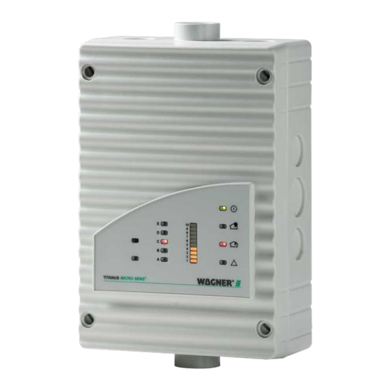
Halma Ampac TITANUS MICRO-SENS Manuals
Manuals and User Guides for Halma Ampac TITANUS MICRO-SENS. We have
1
Halma Ampac TITANUS MICRO-SENS manual available for free PDF download: Technical Manual
Halma Ampac TITANUS MICRO-SENS Technical Manual (229 pages)
Aspirating smoke detector
Brand:
Halma
| Category:
Security Sensors
| Size: 9 MB
Table of Contents
Table of Contents
2
General Information
6
Introduction
6
Safety Notices
6
Personal Injury
7
Material and Environmental Damage
7
Other Notices
7
Warranty
8
Copyright
8
Packaging
9
Environmental Protection
9
Instructions for the User
10
Product Description
11
Characteristics
11
Areas of Application
14
Technical Description
18
System Description
18
Function
19
Layout and Accessory Components
24
Overview
24
Device
25
Reset Circuit Board
28
Diagnostic Tool
29
Detector Box
30
Network Module
34
Remote Display
36
Response Indicator
37
Pipe System
38
Entire Overview of Available Pipe Components
38
Air Purge System
40
Aspiration Apertures
44
Ceiling Feed-Through
47
Air Filter and Special Filter
49
Air Return for Pressure Differences and Air Pollution
53
Silencer
55
Condensate Separator
56
Technical Data
58
Device
58
Accessories
59
Detector Box
60
Remote Displays
61
Response Indicator
62
Relay Module
62
Reset Circuit Board
62
Network Module
63
Pipe System
63
Project Planning
64
General Information
64
Laws, Standards and Guidelines
65
Pipe System
66
Air Flow Monitoring
71
Sensitivity
72
Project Planning Limits
73
Project Planning Guidelines
74
Determination of Necessary Pipe Accessories
74
Detailed Pipe Accessories
75
Procedure for Pipe Project Planning
76
Determination of Aspiration Aperture Diameter
79
Special Project Planning
82
Project Planning with Single Hole Monitoring
82
Simplified Project Planning
90
Project Planning with Stubs
95
Project Planning with Forced Air Flow
99
Project Planning with Aspiration Hose
104
Project Planning with Air Return
105
Energy Supply
106
Installation
110
General Information
110
Determination of Installation Location
111
Installation of Device
112
Establishing the Electrical Connection
115
Connecting to an FDCP, with Reset Button
119
Inserting and Connecting the Reset Circuit Board
119
Inserting and Connecting the Reset and Disconnect Button Circuit Board
123
Inserting and Connecting Relay Module Type RU-1/RU-2
125
Inserting and Connecting Network Module
128
Connecting Remote Display
132
Attaching the Front Film Sheet
134
Connecting and Addressing the Response Indicator
134
Inserting the Detection Unit in the Device Base
137
General Information on the Pipe System
138
Length Alterations on the Pipe System
138
Installation of the Pipe System
141
Installation of the Aspiration Pipe
143
Installation of the Aspiration Hose
143
Installation of Aspiration Apertures
145
Installation of Aspiration-Reducing Clips
147
Installation of the Ceiling Feed-Through
149
Mounting Ceiling Feed-Through for Suspended Ceilings
149
Installation of the Ceiling Feed-Through for Special Applications
151
Installation of Pipe System on Forced Air Flow Monitoring
153
Detection of Supply and Exhaust Air Openings
153
Detection in the Bypass
154
Installing the Air Filter or Special Filter
154
Installing Air Filter Type LF-AD or LF-AD-X
155
Installing Special Filter Type SF-400/650
157
Installing a Combination of Air Filter and Special Filter
158
Installation of Air Return
159
Installing a Silencer
160
Installation of 3-Way Ball Valve
162
3-Way Ball Valve (ABS/PVC)
162
3-Way Ball Valve (Metal)
164
Installation of the Condensate Separator
166
Condensate Separator Type KA-1
166
Condensate Separator Type KA-DN 25
167
Installation of Test Adapter
168
Commissioning
169
Commissioning the Detection Unit
169
Plug-And-Play Commissioning
170
Commissioning Using Diagnostic Tool
171
Making Settings Using the Diagnostic Software
175
Selecting the Sensitivity (MA)
176
Setting the Alarm Delay
177
Setting the Air Flow Range
177
Setting the Fault Delay
178
Setting the Pre-Alarm Threshold (Optional)
178
Activating or Deactivating the Memory Fault Display
178
Activating or Deactivating Dynamic Air Flow
179
Activating or Deactivating ROOM·IDENT (Optional)
179
Activating or Deactivating LOGIC·SENS
179
Activating or Deactivating Main Alarm after ROOM·IDENT (Optional)
180
Setting the Height above Sea Level
180
Setting the Current Air Pressure
180
Setting the Fan Voltage
181
Calibration of Air Flow Sensor
181
Air Pressure-Independent Calibration
182
Air Pressure-Dependent Calibration
183
Checking the Detection Unit and Alarm Signal Transmission
185
Checking the Air Flow Monitoring and Fault Signal Transmission
186
Function Test
187
Preparing for the Function Test
187
Performing the Function Test
190
Commission ROOM·IDENT
194
Commissioning Response Indicators
200
Maintenance
202
Maintenance Intervals
202
Visual Inspection
202
Checking the Detection Unit and Alarm Signal Transmission
203
Pipe System Check
204
Purging the Pipe System
204
Replacing the Detection Unit
208
Replacing Filter Elements in the Device Base
210
Replacing the Filter Elements of Air Filter Type LF-AD-X
211
Replacing the Filter Elements of Special Filter Type SF-400 / 650
212
Checking the Air Flow Sensor Calibration
213
Checking ROOM·IDENT and Response Indicators
215
Checking the Air Flow Monitoring and Fault Signal Transmission
217
Glossary
218
Appendix
222
Advertisement
Advertisement
Related Products
Halma Ampac FastSense PLUS
Halma Ampac LST
Halma Ampac TITANUS PRO-SENS
Halma Ampac TITANUS PRO-SENS-SL
Halma Ampac Test Set
Halma Ampac XPander
Halma Ampac LoopSense
Halma Ampac FireFinder
Halma Ampac EvacUElite
Halma AMPAC FireFinder Series
Halma Categories
Measuring Instruments
Controller
Security Sensors
Accessories
Control Panel
More Halma Manuals
Login
Sign In
OR
Sign in with Facebook
Sign in with Google
Upload manual
Upload from disk
Upload from URL