Sign In
Upload
Manuals
Brands
GW Instek Manuals
Measuring Instruments
LCR-6000 Series
GW Instek LCR-6000 Series Manuals
Manuals and User Guides for GW Instek LCR-6000 Series. We have
1
GW Instek LCR-6000 Series manual available for free PDF download: User Manual
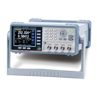
GW Instek LCR-6000 Series User Manual (143 pages)
LCR Meter
Brand:
GW Instek
| Category:
Measuring Instruments
| Size: 2 MB
Table of Contents
Safety Summary
3
Table of Contents
5
Table of Figures
12
List of Tables
14
Unpacking and Preperation
15
Incoming Inspection
15
Environmental Requirements
16
Cleaning
16
How to Remove the Handle
17
Figure 1-1 How to Remove the Handle
17
Overview
18
Introduction
18
Main Specifications and Features
19
Test Function
19
Equivalent Circuit
19
Ranging
19
Measurement Speed
19
Table 2-1 Equivalent Circuit
19
Trigger Mode
20
Basic Accuracy
20
Display Range
20
Table 2-2 Display Range
20
Test Signal
21
Test Signal Frequency
21
Test Signal Level
21
Output Impedance
21
Main Functions
22
Correction Function
22
Comparator Function (Sorting)
22
List Sweep
22
Measurement Assistance Functions
23
Files
23
Key Lock
23
Options
23
USB Host Port
23
DC Bias Voltage
24
Figure 2-1 Disk Ready
24
Figure 2-2 Screen Saved
24
Startup
25
Front Panel
25
Figure 3-1 Front Panel
25
Table 3-1 Front Panel Description
25
Rear Panel
26
Power On/Off
26
Power on
26
Power off
26
Figure 3-2 Rear Panel
26
Table 3-2 Rear Panel Description
26
Warm-Up Time
27
Connect to the Device under Test (DUT)
27
Figure 3-3 Connect to DUT
27
Measure Key
28
MEAS DISPLAY] Page
28
Measurement Function [FUNC]
29
Figure 4-1 [MEAS DISPLAY] Page
29
Table 4-1 Measurement Parameter Combinations
29
Table 4-2 Monitor Parameters
29
Table 4-3 Measurement and Monitor Parameter Descriptions
30
Impedance Range [RANGE]
31
Table 4-4 Impedance Range Mode
31
Table 4-5 Effective Measurement Range for the Impedance Range When in HOLD State
32
Table 4-6 DCR FUNC Effective Measurement Range for the Impedance Range When in HOLD State
32
Test Frequency [FREQ]
33
Table 4-7 Frequency Range and Resolution
33
Table 4-8 LCR-6300'S Predefined Test Frequencies that Can be Selected by Using INCR+/DECR
34
Table 4-9 LCR-6200'S Predefined Test Frequencies that Can be Selected by Using INCR+/DECR
34
Table 4-10 LCR-6100'S Predefined Test Frequencies that Can be Selected by
34
Table 4-11 LCR-6020'S Predefined Test Frequencies that Can be Selected by
34
Trigger Mode [TRIG]
35
Table 4-12 LCR-6002'S Predefined Test Frequencies that Can be Selected by
35
Test Signal Voltage/Current Level [LEVEL]
36
Table 4-13 Test Voltage/Current Level that Can be Selected with
36
Measurement Speed [SPEED]
37
Measurement Log [LOG]
38
OPEN/SHORT] Page
41
Figure 4-2 [OPEN/SHORT] Page
41
Open Correction [OPEN]
42
Figure 4-3 Stray Admittance
42
Short Correction [SHORT]
43
Figure 4-4 Residual Impedances
43
SPOT Correction
44
LIST SETUP] Page
46
Measurement Function [FUNC]
46
Figure 4-5 [LIST SETUP] Page
46
Test Mode [MODE]
47
List Measurement Parameters
48
List Point and Limit Modes
48
LIST MEAS] Page
50
Trigger Mode [TRIG]
50
Figure 4-6 [LIST MEAS] Page
50
Test Mode [MODE]
51
Range Mode [RANGE]
52
Measurement Log [LOG]
52
ENLARGE DISPLAY] Page
54
Enlarge Display
54
Direct Comparison Function
55
Figure 4-7 [ENLARGE DISPLAY] Page
55
Figure 4-8 Direct Comparison Setting
55
Setup Key
56
MEAS SETUP] Page
56
Figure 5-1 [MEAS SETUP] Page
56
Source Output Impedance [SRC RES]
58
Averaging Factor [AVG]
58
DC Bias Voltage [BIAS]
59
Auto LCZ Function [AUTO LCZ]
59
Monitor 1 and Monitor 2 [MON 1][MON 2]
60
Measurement Delay [DELAY]
61
Auto Level Control [Alc]
61
Nominal Value [NOMINAL]
61
BIN SETUP] Page
62
Measurement Function [FUNC]
63
Comparator Function ON/OFF
63
Figure 5-2 [BIN SETUP] Page
63
Figure 5-3 Page Comparator Workflow
64
Auxiliary bin [AUX]
65
Primary Parameter Comparator Limit Mode [MODE]
65
Figure 5-4 Absolute Mode
66
Figure 5-5 Percentage Mode
66
Figure 5-6 Sequential Mode
67
Nominal Value for Tolerance Mode
68
Beep Feature
68
Total Number of Bins [#-BINS]
68
Lower and Upper Limits
69
BIN MEAS] Page
69
Comparator Function ON/OFF
70
Figure 5-7 [BIN MEAS] Page
70
Auxiliary bin [AUX]
71
BIN COUNT] Page
71
Figure 5-8 [BIN COUNT] Page
71
Counter Function [COUNT]
72
System Configurations
73
SYSTEM CONFIG] Page
73
Setting the System Date and Time
74
Figure 6-1 [SYSTEM CONFIG] Page
74
Account Setting
75
KEY BEEP Setting
76
Baud Rate
76
Hand Shake
77
Error Code
78
Result
79
Data Buffer
79
Default Set
80
SYSTEM INFO] Page
81
Figure 6-2 [SYSTEM INFO] Page
81
File Operation
82
FILE] Page
82
Figure 7-1 [FILE] Page
82
Media]
83
Recall a File at Startup [AUTO RECALL]
83
Auto Save Data to Last File [AUTO SAVE]
84
File Operation
84
Handler Interface
85
Pin Assignment
86
Figure 8-1 Pin Assignment
86
Table 8-1 Handler Interface Signals ~ Output Pins
86
Table 8-2 Handler Interface Signals ~ Input Pins
87
Table 8-3 Handler Interface Signals ~ Power Pins
87
Connection
88
Figure 8-2 Circuit of Input Pins
88
Timing Chart for Handler Interface
89
Figure 8-3 Circuit of Output Pins (bin Sorting, Index, EOM)
89
Figure 8-4 Timing Chart
89
Table 8-4 Timing Definitions
89
Examples
90
Basic Measurement Procedure
90
Example
91
Figure 9-1 Basic Measurement Procedure
91
Figure 9-2 Measurement Results
94
Remote Control
95
About RS-232C
95
Figure 10-1 the RS-232 Connector on the Real Panel
95
To Select Baud Rate
96
Figure 10-2 PC - LCR-6000 Series Connection Uses a Null Modem Connection
96
SCPI Language
97
Command Reference
98
Terminator
98
Notation Conventions and Definitions
98
Command Structure
98
Figure 11-1 Command Tree Example
99
Header and Parameters
100
Table 11-1 Multiplier Mnemonics
101
Command Reference
102
Display Subsystem
103
Disp:line
103
Disp:page
103
Figure 11-2 Command Tree Example
103
Function Subsystem
105
Function
105
Figure 11-3 Function Subsystem Tree
105
Function:impedance:auto
106
Function:impedance:range
106
Function:dcr:range
106
Function:range:auto
107
Function:monitor1 /2
107
Figure 11-4 FREQ Subsystem Command Tree
108
Level Subsystem
109
Level:voltage (=Voltage[:Level])
109
Figure 11-5 Level Subsystem Command Tree
109
Level:current (=Current[:Level])
110
Level:sresistance (= Voltage:sresistance)
110
Level:alc (=Amplitude:alc)
111
Level:mode
111
Aperture Subsystem
112
Aperture:rate
112
Aperture:avg
112
Figure 11-6 Aperture Subsystem Command Tree
112
Fetch Subsystem
113
Fetch
113
Figure 11-7 Fetch Subsystem Command Tree
113
Fetch:impedance
114
Fetch:main
114
Fetch:monitor1? /2
114
Fetch:monitor
114
Fetch:list
115
Comparator Subsystem
116
Figure 11-8 Comparator Subsystem Command Tree
116
Comparator:state
117
Comparator:mode
117
Comparator:aux
117
Comparator:bins
118
Comparator:tolerance:nominal
118
Comparator:tolerance:bin
118
Comparator:slim
119
Comparator:beep
119
Comparator:open
120
LIST Subsystem
120
List:parameter
120
Figure 11-9 LIST Subsystem Command Tree
120
List:stat
121
List:band
121
Correction Subsystem
122
Correction:open
122
Figure 11-10 Correction Subsystem Command Tree
122
Correction:open:state
123
Correction:short
123
Correction:short:state
123
Correction:spot:frequency
124
Correction:spot:open
124
Correction:spot:short
124
Trigger Subsystem
125
Trigger[:Immediate]
125
Trigger:source
125
Figure 11-11 Trigger Subsystem Command Tree
125
Trigger:delay
126
BIAS Subsystem
126
Figure 11-12 BIAS Subsystem Command Tree
126
FILE Subsystem
127
File
127
File:save
127
File:load
127
Figure 11-13 FILE Subsystem Command Tree
127
File:delete
128
Error Subsystem
128
Error
128
SYSTEM Subsystem
128
System:shakehand
128
System:code
129
System:keylock
129
System:result
129
Common Commands
129
Idn
129
Trg
130
Sav
130
Rcl
130
Specification
131
General Specification
131
Dimensions
135
Figure 12-1 Dimensions
135
Accuracy
136
Accuracy
137
L, C, R |Z| Measurement Accuracy
137
Accuracy for D
137
Accuracy for Q
138
Accuracy for
138
Correction Factors that Affect Measurement Accuracy
139
Figure 13-1 the Basic Measurement Accuracy a
140
Figure 13-2 Table for Basic Accuracy Correction Factor a
141
Table 13-1 Impedance Correction Factors
141
Table 13-2 Temperature Correction Factor K
142
Table 13-3 Correction Factor for Interpolated Open/Short Trimming K Table 13-4 Correction Factors for the Cable Length of Test Leads K L
142
Declaration of Conformity
143
Advertisement
Advertisement
Related Products
GW Instek LCR-6300
GW Instek LCR-6200
GW Instek LCR-6020
GW Instek LCR-6002
GW Instek LCR-6100
GW Instek LCR-817
GW Instek LCR-826
GW Instek LCR-8110G
GW Instek LCR-8205
GW Instek LCR-1100
GW Instek Categories
Measuring Instruments
Test Equipment
Power Supply
Multimeter
Portable Generator
More GW Instek Manuals
Login
Sign In
OR
Sign in with Facebook
Sign in with Google
Upload manual
Upload from disk
Upload from URL