Sign In
Upload
Manuals
Brands
GUDEL Manuals
Industrial Equipment
TMO-4 V2.20
GUDEL TMO-4 V2.20 Manuals
Manuals and User Guides for GUDEL TMO-4 V2.20. We have
1
GUDEL TMO-4 V2.20 manual available for free PDF download: Operating Manual
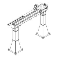
GUDEL TMO-4 V2.20 Operating Manual (342 pages)
Brand:
GUDEL
| Category:
Industrial Equipment
| Size: 12.99 MB
Table of Contents
Table of Contents
14
Table -1 Revision History
3
Table 10-11 Malfunctions / Troubleshooting
3
Table of Contents
14
Table 2-1 Explanation of Symbols/Abbreviations
20
Fig. 3 -1 Danger Label "Danger Sign
29
Fig. 3 -2 Danger Label "Tearing Due to Rack
30
Fig. 4 -1 Type Plate
36
Fig. 4 -2 Position of the Type Plate
36
Table 4-1 Temperature Ranges
37
Fig. 5 -1 Design
39
Fig. 5 -2 Double Roller Support Option
40
Fig. 5 -3 Fastening Types
41
Fig. 5 -4 Axis Names
42
Fig. 6 -1 Attaching Slings
44
Fig. 6 -2 Packaging Symbols
44
Table 6-1 Guard Plates Material Numbers
46
Fig. 6 -3 Attaching the Slings: Beam
46
Fig. 6 -4 Attaching the Slings: Güdel Uprights
47
Fig. 7 -1 Attaching the Slings: Beam
55
Table 7-1 Guard Plates Material Numbers
56
Fig. 7 -2 Attaching the Slings: Güdel Uprights
57
Table 7-2 Special Tools, Testing and Measuring Instruments
60
Fig. 7 -3 Positioning the Base Plates: Position Points
61
Fig. 7 -4 Clean the Bore Hole: HIT-Z / HIT-HY-200A
62
Fig. 7 -5 Setting up an Upright
63
Fig. 7 -6 Measuring Height of Upright
65
Table 7-3 Change in Height Resulting from One Rotation of the Floor Leveling Screw
66
Fig. 7 -7 Marking Floor Leveling Screw
66
Fig. 7 -8 Installing a Beam: Standard
68
Fig. 7 -9 Connecting the Beams
69
Fig. 7 -10 Straightening Beams
70
Fig. 7 -11 Aligning Upright and Beam
72
Fig. 7 -12 Danger Label "Provisionally Assembled Bumper Unit
74
Fig. 7 -13 Bumper Unit with Shearing Sleeves
75
Fig. 7 -14 Bumper Unit with Pins
76
Fig. 7 -15 Bumper Unit with Mechanical Limit Stops
77
Table 7-4 Anchored Base Mounting: HAS / HVU
79
Fig. 7 -16 Base Mounting with Adhesive Anchor: HAS / HVU
79
Table 7-5 Welded Base Mounting: HST3
82
Fig. 7 -17 Welded Base Mounting: HST3
82
Fig. 7 -18 Welded Base Mounting: HAS-TZ / HVU-TZ
83
Table 7-6 Welded Base Mounting: HAS-TZ / HVU-TZ
84
Table 7-7 Welded Base Mounting: HIT-Z / HIT-HY-200-A
85
Fig. 7 -19 Welded Base Mounting: HIT-Z / HIT-HY-200-A
85
Fig. 7 -20 Mounting Aid for Rack Installation
87
Fig. 7 -21 Installing the Rack
88
Table 7-8 Cleaning Agents: Rack
88
Fig. 7 -22 Check Rack Transition
90
Table 7-9 Permissible Deviation, Rack Transition
91
Fig. 7 -23 Installing the Guideway
92
Table 7-10 Cleaning Agents: Guideway
92
Fig. 7 -24 Aligning the Gearbox Flange
94
Fig. 7 -25 Aligning the Input Shaft to the Gearbox Flange
96
Fig. 7 -26 Positioning the Coupling on the Motor Shaft: Elastomer Coupling
98
Fig. 7 -27 X Dimension Calculation Formula
98
Table 7-11 Cleaning Agents: Gearbox Unit Güdel: Coupling and Motor Shaft
98
Table 7-12 Weight and Tolerances for the Elastomer Coupling
100
Table 7-13 Special Tools, Testing and Measuring Instruments
100
Fig. 7 -28 Installing the Motor and Coupling
102
Table 7-14 Cleaning Agents: Güdel Gearbox Unit: Coupling, Input Shaft and Wedge
102
Table 7-15 Special Tools, Testing and Measuring Instruments
102
Fig. 7 -29 Changing the Lubricating Position
104
Fig. 7 -30 Checking Leveling of the Guide Chute
105
Fig. 7 -31 Connecting the Side Panels
106
Fig. 7 -32 Laying Cables and Lines (Image Source: IGUS)
109
Fig. 7 -33 Installing the Energy Chains
111
Fig. 7 -34 Installing the Slide Bars (Image Source: IGUS)
112
Fig. 7 -35 Relieving the Strain on Cables and Lines (Image Source: IGUS)
114
Table 7-16 Strain Relief: Cable Fitting / Chainfix Version
114
Fig. 7 -36 Installing the Robot
116
Fig. 7 -37 Removing Transport Securing Device: Güdel Gearbox Unit
118
Fig. 7 -38 Installing Transport Securing Device: Güdel Gearbox Unit
120
Fig. 7 -39 Checking the Transport Securing Device
122
Fig. 7 -40 Clean Guideways and Racks
124
Table 7-17 Cleaning Agents: Guideways, Racks
124
Fig. 7 -41 Pre-Lubricate Guideways and Racks
125
Table 7-18 Lubricants: Guideways, Racks, and Pinions
125
Fig. 7 -42 Carrying out a Lubrication Check
126
Table 7-19 Lubricants: Guideways, Racks, and Pinions
126
Table 9-1 Table of Cleaning Agents
133
Fig. 9 -1 Lubricating Manually with Grease
135
Fig. 9 -2 Lubricating Manually with Oil
135
Table 9-2 Lubricants: Guideways, Racks, and Pinions
135
Table 9-3 Lubricants: Guideways, Racks, and Pinions
135
Fig. 9 -3 Lubricating Manually with Oil
136
Fig. 9 -4 Markings at the Lubrication Points
136
Table 9-4 Lubricants: Pre-Lubricate Guideways and Racks
136
Table 9-6 Lubricants: Automatic Lubrication System Flexxpump: Prelubricate Guideways and Racks
137
Fig. 9 -5 Automatic Lubrication System Flexxpump
137
Fig. 9 -6 Automatic Lubrication System Flexxpump
137
Table 9-5 Lubricants: Automatic Lubrication System Flexxpump
137
Table 9-7 Lubricants: Automatic Lubrication System Memolub
138
Table 9-8 Lubricants: Automatic Lubrication System Memolub
138
Fig. 9 -7 Automatic Lubrication System Memolub
138
Fig. 9 -8 Automatic Lubrication System Memolub
138
Table 9-9 Lubricant Table
140
Table 9-10 Maintenance Intervals in Shift Operation (5 Days a Week)
142
Table 9-11 Maintenance Intervals in Shift Operation (7 Days a Week)
142
Table 9-12 Special Tools, Testing and Measuring Instruments
144
Table 9-13 Lubricants: Guideways, Racks, and Pinions
147
Fig. 9 -9 Carrying out a Lubrication Check
147
Fig. 9 -10 Lubricating Components on the Grease Nipple
148
Table 9-14 Lubricants: Guideways, Racks, and Pinions
149
Table 9-15 Inspection Table
152
Table 9-16 Lubricants: Roller
153
Fig. 9 -11 Greasing the Roller
153
Fig. 9 -12 Carrying out a Lubrication Check
155
Table 9-17 Lubricants: Guideways, Racks, and Pinions
155
Fig. 9 -13 Replacing the Lubricating Pinion
156
Table 9-18 Lubricants: Guideways, Racks, and Pinions
156
Fig. 9 -14 Replacing the Wiper and Lubricating Element
158
Table 9-19 Lubricants: Guideways, Racks, and Pinions
158
Table 9-20 Inspection Table
160
Fig. 9 -15 Laying Cables and Lines (Image Source: IGUS)
163
Fig. 9 -16 Installing the Energy Chains
165
Fig. 9 -17 Installing the Slide Bars (Image Source: IGUS)
167
Fig. 9 -18 Attaching the Slings: Motor (Image Source: Bosch Rexroth)
168
Fig. 9 -19 Attaching the Slings: Güdel Gearbox Unit
169
Table 9-21 Size of Lifting Screw
169
Fig. 9 -20 Remove Motor and Coupling
171
Fig. 9 -21 Removing the Gearbox Unit
172
Fig. 9 -22 Installing the Gearbox Unit
174
Table 9-22 Tightening Torques for Gearbox Screws: Güdel Gearbox Unit
174
Fig. 9 -23 Aligning the Gearbox Flange
176
Fig. 9 -24 Aligning the Input Shaft to the Gearbox Flange
178
Fig. 9 -25 Positioning the Coupling on the Motor Shaft: Elastomer Coupling
180
Fig. 9 -26 X Dimension Calculation Formula
180
Table 9-23 Cleaning Agents: Gearbox Unit Güdel: Coupling and Motor Shaft
180
Table 9-24 Weight and Tolerances for the Elastomer Coupling
182
Table 9-25 Special Tools, Testing and Measuring Instruments
182
Fig. 9 -27 Installing the Motor and Coupling
184
Table 9-26 Cleaning Agents: Güdel Gearbox Unit: Coupling, Input Shaft and Wedge
184
Table 9-27 Special Tools, Testing and Measuring Instruments
184
Fig. 9 -28 Roller Holder Installation Types
186
Fig. 9 -29 Roller Holder Arrangement
187
Fig. 9 -30 Roller Holder Arrangement: TMF-5 Double Roller Support
187
Fig. 9 -31 Replacing the Roller
188
Table 9-28 Distinguishing Characteristics of Wear: Roller
188
Fig. 9 -32 Setting the Lateral Rollers
190
Fig. 9 -33 Setting the Remaining Rollers
192
Fig. 9 -34 Unloaded Roller E2
193
Fig. 9 -35 Zero Position of Eccentric
195
Table 9-29 Cleaning Agents: Guideway
197
Fig. 9 -36 Installing the Guideway
197
Fig. 9 -37 Mounting Aid for Rack Installation
199
Table 9-30 Cleaning Agents: Rack
200
Fig. 9 -38 Installing the Rack
200
Fig. 9 -39 Check Rack Transition
202
Table 9-31 Permissible Deviation, Rack Transition
203
Fig. 9 -40 Eccentric Marking: Drill Hole
205
Fig. 9 -41 Eccentric Marking: Countersink Separate
205
Fig. 9 -42 Blocking the Eccentric Ring: Hexagonal Screw
206
Fig. 9 -43 Setting the Tooth Flank Backlash: Eccentric
207
Fig. 9 -44 Blocking the Drive Pinions: Güdel Gearbox Unit
208
Table 9-32 Rack Quality and Module
209
Table 9-33 Tooth Flank Backlash: Güdel Gearbox Unit
209
Fig. 9 -45 Checking the Tooth Flank Backlash: Dial Gauge (Exact Method)
210
Table 9-34 Tooth Flank Backlash: Paper Strip (Inexact Method)
211
Fig. 9 -46 Checking the Tooth Flank Backlash: Paper Strip (Inexact Method)
212
Fig. 9 -47 Maintenance Schedule
215
Fig. 9 -48 Güdel Gearbox Unit Maintenance Schedule
217
Fig. 9 -49 Maintenance Schedule for Automatic Lubrication System
219
Table 9-35 Maintenance Table
221
Fig. 9 -50 Identification Number of the Instructions
233
Fig. 10 -1 Attaching the Slings: Motor (Image Source: Bosch Rexroth)
237
Fig. 10 -2 Attaching the Slings: Güdel Gearbox Unit
238
Table 10-1 Size of Lifting Screw
238
Fig. 10 -3 Removing the Motor: Güdel Gearbox Unit
239
Fig. 10 -4 Removing the Gearbox Unit
240
Fig. 10 -5 Replacing Lubricant: Güdel Gearbox Unit
242
Table 10-2 Lubricants: Gearbox Unit Güdel
242
Fig. 10 -6 Installing the Gearbox Unit
243
Table 10-3 Tightening Torques for Gearbox Screws: Güdel Gearbox Unit
244
Fig. 10 -7 Installing the Motor: Güdel Gearbox Unit
244
Table 10-4 Lubricants: Güdel Gearbox Unit: Elastomer Gear Rim of the Coupling
245
Table 10-5 Special Tools, Testing and Measuring Instruments
246
Fig. 10 -8 Replacing the Motor: Positioning the Coupling Half on the Motor Shaft
246
Fig. 10 -9 Replacing the Motor Flange and Gearbox Flange
248
Table 10-6 Distinguishing Characteristics of Wear: Pinion
249
Table 10-7 Distinguishing Characteristics of Wear: Bearing
249
Table 10-8 Distinguishing Characteristics of Wear: Clamping Set
249
Fig. 10 -10 Replacing Pinion, Bearing, and Clamping Set: Güdel Gearbox Unit
250
Table 10-9 Tightening Torques of Screws of Casing Cover
252
Fig. 10 -11 Setting the Gear Backlash: Güdel Gearbox Unit
252
Table 10-10 Distinguishing Characteristics of Wear: Elastomer Gear Rim
254
Fig. 10 -12 Elastomer Gear Rim
254
Fig. 10 -13 Bumper Unit with Shearing Sleeves
256
Fig. 10 -14 Bumper Unit with Pins
257
Fig. 10 -15 Bumper Unit with Mechanical Limit Stops
258
Service Departments
263
Table 12-1 Disposal: Material Groups
272
Table 13-1 Service Departments Americas
276
Table 13-2 Service Departments in Asia
277
Table 13-3 Service Departments in Europe
279
Table 13-4 Service Departments for All Other Countries
279
Table 13-5 Service Departments Outside of Business Hours
279
Explanations Regarding the Spare Parts List
281
Position Drawings
281
Fig. 13 -1 Explanation of Symbols
281
Torque Tables
282
Tightening Torques for
282
Zinc Plated Screws
283
Table 14-1 Torque Table for Zinc-Plated Screws Lubricated with Molykote (Mos2) Grease
283
Black Screws
284
Table 14-2 Torque Table for Black Oiled and Non-Lubricated Screws
284
Stainless Steel Screws
285
Table 14-3 Torque Table for Stainless Steel Screws Lubricated with Molykote (Mos2) Grease
285
Tightening Torques for Roller Holders
286
Fig. 14 -1 Tightening Torques for Roller Holders
286
Table 14-4 Tightening Torques for Roller Holders
286
Tightening Torques for HV Sets
287
Table 14-5 Tightening Torques for the HV Set
287
Tightening Torques for Clamping Sets
288
Fig. 14 -2 Tightening the Clamping Set
288
Fig. 14 -3 Releasing the Clamping Set
288
Table 14-6 Torque Table for Clamping Sets
288
Thread Rolling Screws
289
Fig. 14 -4 Use of Thread Rolling Screws
289
Table 14-7 Tightening Torques for Thread Rolling Screws
289
Illustrations
291
Advertisement
Advertisement
Related Products
GUDEL TMO Series
GUDEL TMO-1 V2.20
GUDEL TMO-2 V2.20
GUDEL TMO-3 V2.20
GUDEL CP 3-5 V2
GUDEL NGHP Series
GUDEL NRH Series
GUDEL NRHP Series
GUDEL ZP 3-5 V4
GUDEL Categories
Lubrication systems
Industrial Equipment
Water Pump
Grinder
Control Unit
More GUDEL Manuals
Login
Sign In
OR
Sign in with Facebook
Sign in with Google
Upload manual
Upload from disk
Upload from URL