
Related Manuals for GUDEL TMO Series

Summary of Contents for GUDEL TMO Series
- Page 1 OPERATING MANUAL BETRIEBSANLE 18014398814262 TMO 1-4 V2 Project / Order: B1M.1xxxxxxx-xxxx Bill of materials: 10xxxxxxxx Serial number: 991xxxxxxx Year of manufacture: 2018...
- Page 2 © GÜDEL Translation of the original instructions This manual contains standard illustrations that may deviate from the original. In the case of special models, options, or technical changes, the scope of deliv- ery may differ from the descriptions here. Reprinting the instructions, in whole or in part, requires our permission.
-
Page 3: Table -1 Revision History
OPERATING MANUAL TMO 1-4 V2 Revision history Revision history Version Date Description 23.04.2018 Valid from product version TMO-1 V2.20; TMO-2 V2.20; TMO-3 V2.20; TMO-4 V2.20 New: • Downtimes Ü Chapter 7.3, 2 51 • Initial lubrication Ü 2 123 • Feedback on the instructions Ü Chapter 9.7, 2 233 • Maintenance tasks after downtimes <4 weeks Ü Chapter 9.3.4, 2 144 •... - Page 4 Revision history OPERATING MANUAL TMO 1-4 V2...
- Page 5 OPERATING MANUAL TMO 1-4 V2 Table of contents Table of contents Declaration of incorporation General 19 Further applicable documentation ....... . . 19 Purpose of the document ...
- Page 6 Table of contents OPERATING MANUAL TMO 1-4 V2 Fundamentals of safety .......... 31 3.4.1 Separating protective equipment, monitoring...
- Page 7 OPERATING MANUAL TMO 1-4 V2 Table of contents Commissioning 49 Introduction ............ 49 7.1.1 Safety ...
- Page 8 Table of contents OPERATING MANUAL TMO 1-4 V2 7.4.7.2 Fixing base with welded joint ......... . . 81 HST3 ...
- Page 9 OPERATING MANUAL TMO 1-4 V2 Table of contents 7.9.1 Clean guideways and racks .......... 123 7.9.2 Pre-lubricate guideways and...
- Page 10 Table of contents OPERATING MANUAL TMO 1-4 V2 9.3.8 Maintenance tasks after 2,250 hours ........ 149 9.3.8.1 General...
- Page 11 OPERATING MANUAL TMO 1-4 V2 Table of contents 9.3.11.5 Replacing the roller ........... . 186 Roller holder installation types ...
- Page 12 Table of contents OPERATING MANUAL TMO 1-4 V2 Maintenance table .......... 221 Intervention protocol: Maintenance .
- Page 13 OPERATING MANUAL TMO 1-4 V2 Table of contents 10.4 Malfunctions / Troubleshooting ........ 259 10.5 Intervention report:...
-
Page 14: Table Of Contents
Table of contents OPERATING MANUAL TMO 1-4 V2 Spare parts supply 273 13.1 Service departments .......... 275 13.2 Explanations regarding the spare parts... - Page 15 OPERATING MANUAL TMO 1-4 V2 Table of contents Appendix Hazard analysis, Risk analysis Addition to declaration of incorporation Technical data Layout Spare parts lists Options Third-party documentation ...
- Page 16 Table of contents OPERATING MANUAL TMO 1-4 V2...
- Page 17 OPERATING MANUAL TMO 1-4 V2 Declaration of conformity, declaration of incorporation Declaration of incorporation The manufacturer: GÜDEL AG Industrie Nord CH-4900 Langenthal hereby declares that the partly completed machine: TMO 1-4 V2 Product, type 991xxxxxxx Serial number 10xxxxxxxx Parts list 2018 Year of manufacture corresponds to the fundamental requirements of the Machinery Directive...
- Page 18 Declaration of conformity, declaration of incorporation OPERATING MANUAL TMO 1-4 V2...
- Page 19 OPERATING MANUAL TMO 1-4 V2 General General Read the entire manual before working with the product. The manual con- tains important information for your personal safety. The manual must be read and understood by all persons who work on the product in any of the product life phases.
-
Page 20: Table 2-1 Explanation Of Symbols/Abbreviations
General OPERATING MANUAL TMO 1-4 V2 Explanation of symbols/abbreviations The following symbols and abbreviations are used in this manual: Symbol / Abbrevia- Explanation tion Ü For cross-reference Possibly for cross-ref- Page erence Fig. Designation of graphics Figure Tab. Designation of tables Table In the tip Information or tip... - Page 21 OPERATING MANUAL TMO 1-4 V2 Safety Safety General Read the entire manual before working with the product. The manual con- tains important information for your personal safety. The manual must be read and understood by all persons who work on the product in any of the product life phases.
- Page 22 Safety OPERATING MANUAL TMO 1-4 V2 Only appropriately trained and authorized technicians are allowed to work on the product. Persons are authorized if: • they are familiar with the relevant safety regulations for their area of re- sponsibility • they have read and understood this manual •...
- Page 23 OPERATING MANUAL TMO 1-4 V2 Safety 3.1.2.3 Fitters The fitter: • has very good mechanical and/or electrical knowledge • is flexible • has assembly experience 3.1.2.4 Commissioning technicians The commissioning technician: • has good programming knowledge • has mechanical and/or electrical knowledge •...
- Page 24 Safety OPERATING MANUAL TMO 1-4 V2 3.1.2.6 Manufacturer's technicians The manufacturer's technician: • is employed on site at the premises of the manufacturer or representative • has very good mechanical and/or electrical knowledge • has good software knowledge • has maintenance, service and repair experience •...
- Page 25 OPERATING MANUAL TMO 1-4 V2 Safety 3.1.2.8 Service technicians The service technician: • was trained by the operating company or the manufacturer • has very good mechanical and/or electrical knowledge • has software knowledge • has service and repair experience •...
- Page 26 Safety OPERATING MANUAL TMO 1-4 V2 3.1.4 Installation instructions The operating company is responsible for ensuring safe conditions in the vicin- Protective mea- sures ity of the product. In particular, he must ensure compliance with the general safety regulations, guidelines and standards. Before commissioning the system the operating company must check whether all the protective measures have been implemented.
- Page 27 OPERATING MANUAL TMO 1-4 V2 Safety Hazard symbols in the manual 3.2.1 Hazard warnings The hazard warnings are defined for the following four types of danger levels: DANGER DANGER DANGER refers to hazards with a high risk of severe physical injury or im- mediate fatality.
- Page 28 Safety OPERATING MANUAL TMO 1-4 V2 3.2.2 Explanation of warning symbol Hazard warnings for personal injuries contain the symbol of the correspond- ing hazard. Symbol Explanation of symbols Hazards due to general causes Hazards due to loose connecting elements Hazards due to overpressure Hazards resulting from automatic startup Hazards due to falling axles Hazards due to heat...
-
Page 29: Fig. 3 -1 Danger Label "Danger Sign
OPERATING MANUAL TMO 1-4 V2 Safety Symbol Explanation of symbols Hazards due to sharp edges of the rack Hazards due to tipping over Hazards due to dangerous electrical voltage Hazard symbols on the product The following warning labels are attached to the product: 3.3.1 Danger label "danger sign"... -
Page 30: Fig. 3 -2 Danger Label "Tearing Due To Rack
Safety OPERATING MANUAL TMO 1-4 V2 3.3.2 Danger label "Tearing due to rack" Fig. 3-2 Danger label "Tearing due to rack" Danger label "Tearing due to rack" • warns against tearing apart lifting belts due to the sharp edges of the rack •... - Page 31 OPERATING MANUAL TMO 1-4 V2 Safety Fundamentals of safety 3.4.1 Separating protective equipment, monitoring equipment WARNING Missing separating protective equipment and monitoring equip- ment Missing or modified separating protective equipment and monitoring equip- ment may result in damage to property or serious injuries! •...
- Page 32 Safety OPERATING MANUAL TMO 1-4 V2 WARNING Falling axes, workpieces Falling axes or workpieces can cause physical damage, serious or fatal injuries! • Set down any workpieces before working in the danger area • Never enter the area below suspended axes and workpieces •...
- Page 33 Read the safety data sheets carefully. Follow all the instructions. We recom- mend that you store the safety data sheets for future reference. The safety data sheet for Güdel H1 can be found in the download area of our company Web site http://www.gudel.com...
- Page 34 Safety OPERATING MANUAL TMO 1-4 V2...
- Page 35 OPERATING MANUAL TMO 1-4 V2 Product description Product description 4.1.1 Intended use The product is intended exclusively for moving and positioning robots. Any other or additional use is not considered to be use in the intended man- ner. The manufacturer assumes no liability for any resulting damage. All risks are carried solely by the user! 4.1.2 Non-intended use...
-
Page 36: Fig. 4 -1 Type Plate
Product description OPERATING MANUAL TMO 1-4 V2 Product designation 4.2.1 Type plate Each product has a type plate. It contains the following information: Fig. 4-1 Type plate Project number, order number Special labeling Sales order item number Product, type Year of manufacture Material number (parts list) Serial number 4.2.2... -
Page 37: Table 4-1 Temperature Ranges
OPERATING MANUAL TMO 1-4 V2 Product description Technical data For the following data, refer to the layout(s) in the appendix. • Dimensions • Weight • Strokes of the individual axes • Gearbox type • Gearbox ratios • Motors The emission sound pressure level depends on the machine properties and Emission sound pressure level the operating conditions. - Page 38 Product description OPERATING MANUAL TMO 1-4 V2...
-
Page 39: Fig. 5 -1 Design
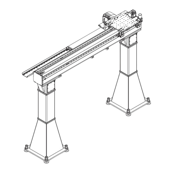
OPERATING MANUAL TMO 1-4 V2 Design, function Design, function Design 5.1.1 TMO 1-4 The product consists of the following assemblies and components: Fig. 5-1 Design Bumper unit Y-Carriage Guide chute Y-drive (Güdel gearbox unit) Y-Axis Automatic lubrication system (option) Lubricating pinion unit Roller support Energy chain Upright... -
Page 40: Fig. 5 -2 Double Roller Support Option
Design, function OPERATING MANUAL TMO 1-4 V2 5.1.2 Double roller support option The product with the double roller support option consists of the following assemblies: Fig. 5-2 Double roller support option Y-Axis Y-Carriage Double roller support Y-drive (Güdel gearbox unit) -
Page 41: Fig. 5 -3 Fastening Types
OPERATING MANUAL TMO 1-4 V2 Design, function 5.1.3 Fastening types The illustrations in this operating manual always show the TMO-E. In some special cases, all three types are described. The product is available in the following fastening types: Fig. 5-3 Fastening types Overhead Trackmotion elevated mount- ing TMO-E Overhead Trackmotion ceiling mounting... -
Page 42: Fig. 5 -4 Axis Names
Design, function OPERATING MANUAL TMO 1-4 V2 Function The product can move along the following axes: Fig. 5-4 Axis names... - Page 43 OPERATING MANUAL TMO 1-4 V2 Transport Transport The product is transported by air, land, or water. The packaging depends on the mode of transport. Truck Shipped on a transport pallet Aircraft Shipped in a crate Ship Shipped in a case or container Only perform the tasks described in this chapter after you have read and un- derstood the chapter "Safety".
-
Page 44: Fig. 6 -1 Attaching Slings
Transport OPERATING MANUAL TMO 1-4 V2 Packaging symbols When moving the transport pallets / crates / cases, observe the following symbols: CENTER OF SLING SLING GRAVITY HERE HERE Fig. 6-1 Attaching slings Center of gravity Fastening point Depending on the contents, the packaging units are marked with the symbols shown below. - Page 45 OPERATING MANUAL TMO 1-4 V2 Transport Remove the packaging only to the degree necessary for company-internal transport. Transport the pallet, crate, or case to the intended installation location. Use appropriate transport devices. Industrial trucks Industrial trucks have to be capable of handling the size and weight of the crate.
-
Page 46: Fig. 6 -3 Attaching The Slings: Beam
Transport OPERATING MANUAL TMO 1-4 V2 Fig. 6-3 Attaching the slings: Beam Screws Transport aids Hook Transport yoke Danger label "Tearing due to rack" Rack Guard plate Lifting belts Product Guard plate material number TMO 3-4 / AP 5-6 / CP 5-6 / 0213768 ZP 6-7 / FP 6-7 / TMF 3-4 P TMO 1-2 / AP 3-4 / CP 3-4 /... -
Page 47: Fig. 6 -4 Attaching The Slings: Güdel Uprights
OPERATING MANUAL TMO 1-4 V2 Transport 6.3.2 Attaching the slings: Güdel uprights WARNING Ripping of lifting belts The sharp edges cut the lifting belts. This can lead to severe or fatal injuries! • Always protect the lifting belts with an edge guard Fig. 6-4 Attaching the slings: Güdel uprights Hook... - Page 48 Transport OPERATING MANUAL TMO 1-4 V2 Attach the slings as follows: Prepare the floor leveling screws according to the illustration If no bottom plate is available: Remove the floor leveling screw Remove the locknut Install the floor leveling screw Mount the locknut in place of the bottom plate on the floor level- ing screw Mount the edge guard (Threads and other sharp edges of the upright have to be protected)
- Page 49 OPERATING MANUAL TMO 1-4 V2 Commissioning Commissioning Introduction Various options are available for your product. This chapter provides informa- tion on several available options. It therefore describes components with which your product is not equipped. 7.1.1 Safety Only perform the tasks described in this chapter after you have read and un- derstood the chapter "Safety".
- Page 50 Commissioning OPERATING MANUAL TMO 1-4 V2 WARNING Incorrectly installed safety component The bumper unit is a safety component. Incorrectly installed bumper units may lead to severe injury or death! • Drill the pinhole into the mating part of the bumper unit if necessary •...
- Page 51 OPERATING MANUAL TMO 1-4 V2 Commissioning Downtimes In some cases, the commissioning of the product may take a significant period of time. If the machine downtime is longer than two weeks, carry out the following jobs: • Check the lubricating film on guideways and racks ü...
- Page 52 Commissioning OPERATING MANUAL TMO 1-4 V2 ü û If the machine downtime is longer than four weeks, carry out the following jobs: • Prelubricate guideways and racks • Perform a lubrication check as described in the separate documentation on automatic lubrication.
- Page 53 OPERATING MANUAL TMO 1-4 V2 Commissioning Setup, fastening 7.4.1 General The following describes the steps for setting up and fastening the product. WARNING Heavy components Components can be very heavy. Improper handling can cause severe or fatal injuries! • Use appropriate lifting units •...
- Page 54 Commissioning OPERATING MANUAL TMO 1-4 V2 7.4.3 Unpacking Accessories and small parts are packaged in a separate case or directly with the product itself. The components have been treated with anti-rust oil (spray) and wrapped in oiled paper. Remove packaging carefully. The anti-rust oil protects the components.
-
Page 55: Fig. 7 -1 Attaching The Slings: Beam
OPERATING MANUAL TMO 1-4 V2 Commissioning 7.4.4 Attaching the slings: Beam WARNING Ripping of lifting belts The sharp edges of the rack cut the lifting belts. This can lead to severe or fa- tal injuries! • Always protect the lifting belts with the guard plate Fig. 7-1 Attaching the slings: Beam Screws... -
Page 56: Table 7-1 Guard Plates Material Numbers
Commissioning OPERATING MANUAL TMO 1-4 V2 Product Guard plate material number TMO 3-4 / AP 5-6 / CP 5-6 / 0213768 ZP 6-7 / FP 6-7 / TMF 3-4 P TMO 1-2 / AP 3-4 / CP 3-4 / 10136821 TMF 1-2 P Table 7-1 Guard plates material numbers... -
Page 57: Fig. 7 -2 Attaching The Slings: Güdel Uprights
OPERATING MANUAL TMO 1-4 V2 Commissioning 7.4.5 Attaching the slings: Güdel uprights WARNING Ripping of lifting belts The sharp edges cut the lifting belts. This can lead to severe or fatal injuries! • Always protect the lifting belts with an edge guard Fig. 7-2 Attaching the slings: Güdel uprights Hook... - Page 58 Commissioning OPERATING MANUAL TMO 1-4 V2 Attach the slings as follows: Prepare the floor leveling screws according to the illustration If no bottom plate is available: Remove the floor leveling screw Remove the locknut Install the floor leveling screw Mount the locknut in place of the bottom plate on the floor level- ing screw Mount the edge guard (Threads and other sharp edges of the upright have to be protected)
- Page 59 OPERATING MANUAL TMO 1-4 V2 Commissioning 7.4.6.1 Special tools, testing and measuring instruments Ensure that you have the following special tools, testing and measuring instru- ments at hand: Tool Item number Sharpening stone Rubbing reference sur- 0503016 faces Adjusting tool Setting the rollers: Size 0919690 40/52...
-
Page 60: Table 7-2 Special Tools, Testing And Measuring Instruments
Commissioning OPERATING MANUAL TMO 1-4 V2 Tool Item number HILTI special tools Anchoring the product Fastening device Blocking the drive pin- 0917454 ions: HPG/AE060 Fastening device Blocking the drive pin- 0917447 ions: HPG/AE090 Fastening device Blocking the drive pin- 0917455 ions: HPG/AE120 Table 7-2 Special tools, testing and measuring instruments... -
Page 61: Fig. 7 -3 Positioning The Base Plates: Position Points
OPERATING MANUAL TMO 1-4 V2 Commissioning Fig. 7-3 Positioning the base plates: Position points Position points (diagonal on plate corners) Reference axis Base plate Position the base plates as follows: Position the base plates according to the foundation plan or layout The base plates are positioned. -
Page 62: Fig. 7 -4 Clean The Bore Hole: Hit-Z / Hit-Hy-200A
Commissioning OPERATING MANUAL TMO 1-4 V2 WARNING Hazard due to tipping Inadequate drill hole cleaning, drill hole filling and failure to adhere to times will result in poor holding strength or failure of the anchors. The product can overturn. This can lead to severe or fatal injuries. •... -
Page 63: Fig. 7 -5 Setting Up An Upright
OPERATING MANUAL TMO 1-4 V2 Commissioning 7.4.6.4 Set up an upright For the product, the following fastening methods are possible: • Güdel uprights • Other uprights • Directly onto a machine • Directly onto a steel beam construction If you are not using Güdel uprights, contact the respective manufacturer. For direct mounting, please observe the hole pattern according to the layout. - Page 64 Commissioning OPERATING MANUAL TMO 1-4 V2 Set up the upright as follows: Set the front floor leveling screws to the specified mass Position the rear floor leveling screws flush with the upright footing Attach the slings as shown in the illustration Place the squared timber on the floor Set up the upright Set the rear floor leveling screws to the specified mass...
-
Page 65: Fig. 7 -6 Measuring Height Of Upright
OPERATING MANUAL TMO 1-4 V2 Commissioning 7.4.6.5 Leveling uprights Measuring height of upright Fig. 7-6 Measuring height of upright Upright Leveling instrument Tape measure Measure the height of the upright as follows: Set up leveling instrument with visual contact to the holes of the uprights Upright 1: Hook tape measure into hole of the upright Measure and write down height of upright... -
Page 66: Fig. 7 -7 Marking Floor Leveling Screw
Commissioning OPERATING MANUAL TMO 1-4 V2 Determining average upright height Determine the average upright height as follows: Add smallest and largest upright heights Divide result by two Round up result to nearest millimeter The average upright height has been determined. Correcting the upright height Also mark the socket when you are working with a socket. - Page 67 OPERATING MANUAL TMO 1-4 V2 Commissioning Correct the height of the upright as follows: Upright 1: Calculate difference between average upright height and height of upright 1 Mark floor leveling screws according to the illustration Loosen locknuts Determine the number of rotations according to the table above Raise or lower all floor leveling screws with the corresponding number of rotations Tighten the locknut...
-
Page 68: Fig. 7 -8 Installing A Beam: Standard
Commissioning OPERATING MANUAL TMO 1-4 V2 ü û Fig. 7-8 Installing a beam: Standard Covering Guideway Upright Wall mounting (e.g. TMO-W; ZP; EP) Beam Ceiling mounting (e.g. TMO-C) Screw Elevated mounting (e.g. TMO-E; CP; AP) Mount the beam as follows: Attach the slings to the beam Lift beam to upright height Remove covering if necessary Mount beam to upright using screws... -
Page 69: Fig. 7 -9 Connecting The Beams
OPERATING MANUAL TMO 1-4 V2 Commissioning 7.4.6.8 Connecting the beams Fig. 7-9 Connecting the beams Fixed beam Spacer sheet Loose beam Sleeve / Centering bolt Washer HV set Connect the beams as follows: Lift the loose beam to the height of the fixed beam (the beams must be flush) Adjust the spacer sheet if necessary Insert sleeves / centering bolts and washers... -
Page 70: Fig. 7 -10 Straightening Beams
Commissioning OPERATING MANUAL TMO 1-4 V2 7.4.6.9 Straightening beams For aligning, use the guideways as a reference. Fig. 7-10 Straightening beams Upright Plate s = 10 mm Guideway Screw clamp Alignment wire Scale... - Page 71 OPERATING MANUAL TMO 1-4 V2 Commissioning Align the beams as follows: Attach two plates of equal thickness and alignment wire to guideway as shown in the illustration Upright 2: Check distance between guideway and alignment wire If there are deviations: Align upright in the corresponding direction Repeat process from step 2.1 Repeat process from step 2 for the remaining uprights Check distance between guideway and alignment wire for all uprights...
-
Page 72: Fig. 7 -11 Aligning Upright And Beam
Commissioning OPERATING MANUAL TMO 1-4 V2 Aligning upright and beam WARNING Hazard due to tipping Using excessive levering force can lead to the upright falling over. This can lead to severe or fatal injuries! • Carefully align the upright and beams Use suitable protective material to avoid damage to the paint. - Page 73 OPERATING MANUAL TMO 1-4 V2 Commissioning 7.4.6.10 Assembling the bumper unit Some bumper units cannot be shipped in a properly assembled state for as- sembly and packaging reasons. In such cases, the entire bumper unit is shipped unassembled. The assembly site is designated with a danger label. Find the correct assembly site on the layout.
-
Page 74: Fig. 7 -12 Danger Label "Provisionally Assembled Bumper Unit
Commissioning OPERATING MANUAL TMO 1-4 V2 Fig. 7-12 Danger label "Provisionally assembled bumper unit" Assembly site of the bumper unit Danger label "Provisionally assembled bumper unit" The danger label "Provisionally assembled bumper unit" warns against • Provisionally assembled or non-assembled bumper units •... -
Page 75: Fig. 7 -13 Bumper Unit With Shearing Sleeves
OPERATING MANUAL TMO 1-4 V2 Commissioning Bumper unit with shearing sleeves Fig. 7-13 Bumper unit with shearing sleeves Bumper block / bumper bracket Bumper Screw Mating part Loctite Blue Threadlocker 7414 Shearing sleeve Assemble the bumper unit with shearing sleeves as follows: Assemble the bumper on the bumper block / bumper bracket Remove the danger label from the assembly site if necessary Install the shearing sleeves at the assembly site... -
Page 76: Fig. 7 -14 Bumper Unit With Pins
Commissioning OPERATING MANUAL TMO 1-4 V2 Bumper unit with pins Fig. 7-14 Bumper unit with pins Loctite Blue Threadlocker 7414 Bumper Screw Bumper block / bumper bracket Mating part Assemble the bumper unit with pins as follows: Assemble the bumper on the bumper block / bumper bracket Remove the danger label from the assembly site if necessary Install pre-assembled bumper unit along with the mating part using pins Tighten the screws... -
Page 77: Fig. 7 -15 Bumper Unit With Mechanical Limit Stops
OPERATING MANUAL TMO 1-4 V2 Commissioning Bumper unit with limit stops Fig. 7-15 Bumper unit with mechanical limit stops Loctite Blue Threadlocker 7414 Bumper block / bumper bracket Screw Mating part Bumper Assemble the bumper unit as follows: Assemble the bumper on the bumper block / bumper bracket Remove the danger label from the assembly site if necessary Clean the contact surface of the mating part meticulously Position the pre-assembled bumper unit on the mating part... - Page 78 Commissioning OPERATING MANUAL TMO 1-4 V2 7.4.7 Anchoring the product The base mounting is available either with an adhesive anchor or with a welded joint. You can find the appropriate anchor type in the layout. NOTE Expansion joints Expansion joints absorb expansion in the foundations. If products are posi- tioned over expansion joints, this expansion is transmitted to the product.
-
Page 79: Fig. 7 -16 Base Mounting With Adhesive Anchor: Has / Hvu
OPERATING MANUAL TMO 1-4 V2 Commissioning The product is anchored with the anchor rod HAS and the HVU adhesive car- HAS / HVU tridge from HILTI. Fig. 7-16 Base mounting with adhesive anchor: HAS / HVU Floor leveling screw Anchor Upright/frame Adhesive cartridge Floor leveling screw M24x2... - Page 80 Commissioning OPERATING MANUAL TMO 1-4 V2 Anchor the upright as follows: Make a bore hole according to the preceding table Clean the bore hole Insert the adhesive cartridge Screw in the anchor rod with the hammer drill Wait until the hardening period specified by the manufacturer has passed Tighten the upright (Select tightening torque according to above table) Remove the safety devices...
- Page 81 OPERATING MANUAL TMO 1-4 V2 Commissioning 7.4.7.2 Fixing base with welded joint This anchoring requires cracked or uncracked concrete with a quality of at least C20/25 (EN 206-1) with ideal stiffness. The minimum concrete thickness and edge clearance are stated in the table below. The information applies ex- clusively to standard Güdel components.
-
Page 82: Fig. 7 -17 Welded Base Mounting: Hst3
Commissioning OPERATING MANUAL TMO 1-4 V2 HST3 The base plate is anchored with the HST3 anchoring bolt from HILTI. Fig. 7-17 Welded base mounting: HST3 Screw Bottom plate Floor leveling screw Anchor Upright/frame Base plate m (floor leveling screw) M24x2 M36x2 Anchor size (concrete thickness) [mm] (edge clearance) [mm]... -
Page 83: Fig. 7 -18 Welded Base Mounting: Has-Tz / Hvu-Tz
OPERATING MANUAL TMO 1-4 V2 Commissioning Weld the joint as follows: Prerequisite:The base plate is anchored to the floor Connect the floor leveling screw and bottom plate by means of the screw Weld the bottom plate to the base plate (Select weld seam type according to above table) Tighten the screw Remove the safety devices... -
Page 84: Table 7-6 Welded Base Mounting: Has-Tz / Hvu-Tz
Commissioning OPERATING MANUAL TMO 1-4 V2 m (floor leveling screw) M48x3 M56x3 Anchor size (concrete thickness) [mm] (edge clearance) [mm] k (fillet weld dimension) [mm] n (joint length) [mm] Table 7-6 Welded base mounting: HAS-TZ / HVU-TZ Weld the joint as follows: Prerequisite:The base plate is anchored to the floor Connect the floor leveling screw and bottom plate by means of the screw... -
Page 85: Fig. 7 -19 Welded Base Mounting: Hit-Z / Hit-Hy-200-A
OPERATING MANUAL TMO 1-4 V2 Commissioning HIT-Z / HIT-HY-200-A The base plate is anchored with the anchor rod HIT-Z and the injection mor- tar HIT-HY-200-A from HILTI. Fig. 7-19 Welded base mounting: HIT-Z / HIT-HY-200-A Screw Bottom plate Floor leveling screw Anchor Upright/frame Base plate... - Page 86 Commissioning OPERATING MANUAL TMO 1-4 V2 Weld the joint as follows: Prerequisite:The base plate is anchored to the floor Connect the floor leveling screw and bottom plate by means of the screw Weld the bottom plate to the base plate (Select weld seam type according to above table) Tighten the screw Remove the safety devices...
-
Page 87: Fig. 7 -20 Mounting Aid For Rack Installation
OPERATING MANUAL TMO 1-4 V2 Commissioning Installing 7.5.1 Using the mounting aid: Installing the rack The start and end of the rack each form half of a tooth gap. For precise and quiet transition, we recommend using a mounting aid toothed in the opposite direction. -
Page 88: Fig. 7 -21 Installing The Rack
Commissioning OPERATING MANUAL TMO 1-4 V2 7.5.2 Installing the rack WARNING Risk of injury For statics-related reasons, the racks come partially pinned ex-factory. Miss- ing pins can cause severe or fatal injuries. • These racks must be pinned after being replaced Fig. 7-21 Installing the rack Screw clamp... - Page 89 OPERATING MANUAL TMO 1-4 V2 Commissioning Install the rack as follows: Prerequisite:For combinations of three or more racks, always start at the middle Clean the reference surfaces and racks thoroughly and rub an sharpening stone across them Clamp rack to reference surfaces with screw clamps (Be sure to apply the screw clamp at the level of the screw to be tight- ened.) Tighten all screws...
-
Page 90: Fig. 7 -22 Check Rack Transition
Commissioning OPERATING MANUAL TMO 1-4 V2 7.5.3 Check rack transition Rack quality and module Ü 2 209 Fig. 7-22 Check rack transition Rack transition Measurement bolt (diameter D = 2 × m ; accuracy: tolerance class 1 acc. to DIN 2269) -
Page 91: Table 7-9 Permissible Deviation, Rack Transition
OPERATING MANUAL TMO 1-4 V2 Commissioning Rack quality Permissible deviation [mm] Module Module m ≤ 3 3 < m ≤ 8 Q4 h21 0.006 0.010 Q5 h22 0.008 0.012 Q6 h23 0.012 0.012 Q7 h25 0.016 0.016 Q8 h27 0.016 0.016 Q9 h27 0.016... -
Page 92: Fig. 7 -23 Installing The Guideway
Commissioning OPERATING MANUAL TMO 1-4 V2 7.5.4 Installing the guideway Fig. 7-23 Installing the guideway Feeler gauge Guideway Reference surfaces Cleaning agents mild universal cleaner free from aromatic compounds (e.g. Motorex OPAL 5000) Table 7-10 Cleaning agents: Guideway Install the guideway as follows: Prerequisite:For axes over 20 meters, the assembly of the guideways must be performed from the middle Clean the reference surfaces and guideways thoroughly and rub a sharp-... - Page 93 OPERATING MANUAL TMO 1-4 V2 Commissioning 7.5.5 Installing the motor 7.5.5.1 Prerequisites Three conditions must be fulfilled simultaneously to allow you to install the motor on the gearbox unit: • The gearbox flange is aligned to allow the coupling screws to be tightened through the drill holes of the gearbox flange with a torque wrench •...
-
Page 94: Fig. 7 -24 Aligning The Gearbox Flange
Commissioning OPERATING MANUAL TMO 1-4 V2 7.5.5.2 Aligning the gearbox flange You can align the gearbox flange. When correctly aligned, the motor and cou- pling can be installed. ü û D1=20F7 02/17 Gearbox side HPG060 Fig. 7-24 Aligning the gearbox flange Articulated socket Coupling Torque wrench... - Page 95 OPERATING MANUAL TMO 1-4 V2 Commissioning Align the gearbox flange as follows: Prerequisite:The gearbox unit is installed on the adjacent construction Ü Chapter 10.2.2.6, 2 243 Switch off the system and secure it with a padlock against being switched on again Remove the plug Check whether the coupling screws can be reached through the drill hole and tightened with a torque wrench If there are deviations:...
-
Page 96: Fig. 7 -25 Aligning The Input Shaft To The Gearbox Flange
Commissioning OPERATING MANUAL TMO 1-4 V2 7.5.5.3 Aligning the input shaft to the gearbox flange WARNING Moving the axis The work requires moving the axis. This can lead to severe or fatal injuries! • Ensure that no persons are in the danger area while the axis is moving Fig. 7-25 Aligning the input shaft to the gearbox flange Drill hole... - Page 97 OPERATING MANUAL TMO 1-4 V2 Commissioning Align the input shaft to the gearbox flange as follows: Prerequisite:The gearbox unit is installed on the adjacent construction Ü Chapter 10.2.2.6, 2 243 Prerequisite:The gearbox flange has been aligned correctly Ü 2 94 Prerequisite:The wedge has been installed on the gearbox side Prerequisite:The coupling has been placed correctly on the input shaft Check whether the coupling screws can be reached through the drill holes...
-
Page 98: Fig. 7 -26 Positioning The Coupling On The Motor Shaft: Elastomer Coupling
Commissioning OPERATING MANUAL TMO 1-4 V2 D2=24H7 02/17 D1=20F7 02/17 Gearbox side HPG060 Fig. 7-26 Positioning the coupling on the motor shaft: Elastomer coupling Gearbox Installation surface Motor flange Coupling screw Measuring instrument Motor shaft Coupling Motor X = Z – Y Fig. 7-27 X dimension calculation formula Cleaning agents... - Page 99 OPERATING MANUAL TMO 1-4 V2 Commissioning Güdel Coupling L dimen- L dimen- Y dimen- X di- type sion sion tol- sion mension gearbox [mm] erance [mm] toler- unit size [mm] ance [mm] +0.5 5103-19- +0.5 15.5 +0.5 5103-14- +0.5 +0.5 5103-24- +0.5 +0.5...
-
Page 100: Table 7-12 Weight And Tolerances For The Elastomer Coupling
Commissioning OPERATING MANUAL TMO 1-4 V2 Güdel Coupling L dimen- L dimen- Y dimen- X di- type sion sion tol- sion mension gearbox [mm] erance [mm] toler- unit size [mm] ance [mm] +1.2 5103-42- +0.5 +1.2 5103-38- +0.5 Table 7-12 Weight and tolerances for the elastomer coupling Tool Item number Corrosion protection... - Page 101 OPERATING MANUAL TMO 1-4 V2 Commissioning 7.5.5.5 Installing the motor and coupling WARNING Heavy components Components can be very heavy. Improper handling can cause severe or fatal injuries! • Use appropriate lifting units • Use suitable means to secure the components against tipping over •...
-
Page 102: Fig. 7 -28 Installing The Motor And Coupling
Commissioning OPERATING MANUAL TMO 1-4 V2 D1=20F7 02/17 Gearbox side HPG060 Fig. 7-28 Installing the motor and coupling Coupling screw Motor Drill hole Coupling Plug Motor screw Motor flange Cleaning agents mild universal cleaner free from aromatic compounds (e.g. Motorex OPAL 5000) Table 7-14 Cleaning agents: Güdel gearbox unit: coupling, input shaft and wedge... - Page 103 OPERATING MANUAL TMO 1-4 V2 Commissioning Install the motor and coupling as follows: Prerequisite:The gearbox unit is installed on the adjacent construction Ü Chapter 10.2.2.6, 2 243 Prerequisite:The gearbox flange has been aligned correctly Ü 2 94 Prerequisite:The input shaft has been aligned correctly to the gearbox flange Ü 2 96 Prerequisite:The couping has been positioned correctly on the motor shaft Ü 2 97...
-
Page 104: Fig. 7 -29 Changing The Lubricating Position
Commissioning OPERATING MANUAL TMO 1-4 V2 7.5.6 Changing the lubricating position Continuous lubrication of the guideways at operating temperatures below 0 °C or with grease requires a modification to the lubricating position. The lubricant channel is inside and carries the lubricant past the lubricating el- ement to the guideway. -
Page 105: Fig. 7 -30 Checking Leveling Of The Guide Chute
OPERATING MANUAL TMO 1-4 V2 Commissioning 7.5.7 Check leveling of the guide chute NOTE Increased wear An incorrectly leveled guide chute leads to increased wear on the energy chain. • Correctly level the guide chute ü û Fig. 7-30 Checking leveling of the guide chute Spirit level Guide chute Check the leveling of the guide chute as follows:... -
Page 106: Fig. 7 -31 Connecting The Side Panels
Commissioning OPERATING MANUAL TMO 1-4 V2 7.5.8 Connecting the side panels Energy chains are guided along laterally by the side panels. The side panels en- sure that the energy chain rolls cleanly along the traverse path. The side pan- els are part of the guide channel. NOTE Breaking the energy chain The energy chain becomes hooked in if the side panel transitions do not align. - Page 107 OPERATING MANUAL TMO 1-4 V2 Commissioning Connect the side panels as follows: Install screw clamps as shown in the illustration Align connecting plates Install pan-head screws from the inner side of the guide chute Apply Loctite 242 to hexagonal nuts Install lock washers and hexagonal nuts Tighten all screw connections Check alignment of transitions...
- Page 108 Commissioning OPERATING MANUAL TMO 1-4 V2 Observe the following points: • Cables are separated by vertical dividers; cables are not permitted to be laid next to each other • Cables laid over each other with different jacket materials need to be sep- arated from each other (risk of sticking) •...
-
Page 109: Fig. 7 -32 Laying Cables And Lines (Image Source: Igus)
OPERATING MANUAL TMO 1-4 V2 Commissioning ü û û ü û ü Fig. 7-32 Laying cables and lines (image source: IGUS) Screwdriver Opening bar Energy chain Vertical divider... - Page 110 Commissioning OPERATING MANUAL TMO 1-4 V2 Lay the cables and lines as follows: Prerequisite:You have read and understood the IGUS assembly instruc- tions Open the opening bar of the energy chain Place the screwdriver on the opening bar Tilt the screwdriver backwards until the opening bar is released Repeat the procedure for the opposite side Remove the opening bar manually Lay the cables and lines in accordance with the IGUS internal division...
-
Page 111: Fig. 7 -33 Installing The Energy Chains
OPERATING MANUAL TMO 1-4 V2 Commissioning The orange flag denotes the driver side. The manufacturer turns the first three chain links on the driver side. This makes the energy chain slide better. ü û Fig. 7-33 Installing the energy chains Orange flag Fastening screw Driver's side connection element Mounting angle... -
Page 112: Fig. 7 -34 Installing The Slide Bars (Image Source: Igus)
Commissioning OPERATING MANUAL TMO 1-4 V2 7.6.3 Installing the slide bars Slide bars are installed on sliding energy chains. The slide bars support the en- ergy chain where is slides over the fixed side. NOTE Breaking the energy chain The energy chain becomes hooked in if the slide bar transitions do not align. The energy chain can break or become prematurely worn! •... - Page 113 OPERATING MANUAL TMO 1-4 V2 Commissioning 7.6.4 Relieving the cables and lines of strain NOTE Incorrectly implemented strain relief Lack of strain relief or incorrectly implemented strain relief on cables and lines in energy chains leads to damage. Cables and lines will be destroyed. This results in operational failure.
-
Page 114: Fig. 7 -35 Relieving The Strain On Cables And Lines (Image Source: Igus)
Commissioning OPERATING MANUAL TMO 1-4 V2 ü û ü û ü û Fig. 7-35 Relieving the strain on cables and lines (image source: IGUS) Fixed side connection element Metal sleeve Versions Explanation Figure Cable fittings Two cable fittings 4.5 mm wide on the appropriate holders ChainFix Tightening torque: 1... - Page 115 OPERATING MANUAL TMO 1-4 V2 Commissioning Attach the strain relief as follows: Position cables and lines in the correct position in accordance with the il- lustration For traverse paths of the energy chain that are less than 50 m: Relieve cable strain at the driver and the fixed side. (distance between the end of the bending movement and strain re- lief of 10-30 times the diameter of the cable) Ensure cable runs straight for at least 20 cm after the strain relief...
-
Page 116: Fig. 7 -36 Installing The Robot
Commissioning OPERATING MANUAL TMO 1-4 V2 7.7.2 Installing the robot WARNING Tipping hazard Screws that are too short can be torn out in the event of a collision with the bumper unit. The robot may tip or fall over. This can lead to severe or fatal injuries. - Page 117 OPERATING MANUAL TMO 1-4 V2 Commissioning 7.7.4 Integrating the product Integrate the product into the complete system. Connect the product with the supply lines for energy and consumables. For information on the proce- dure, refer to the documentation on the complete system. Transport securing devices At delivery, a transport securing device is in effect at the rack or the gearbox.
-
Page 118: Fig. 7 -37 Removing Transport Securing Device: Güdel Gearbox Unit
Commissioning OPERATING MANUAL TMO 1-4 V2 Fig. 7-37 Removing transport securing device: Güdel gearbox unit Plug Coupling Transport securing device Latch Coupling screw Remove the transport securing device as follows: Secure carriage or axis Remove the plug Release the coupling screws If necessary, bend the latch so that it is straight, as shown in the illustra- tion Use the latch to remove the transport securing device in the direction of... - Page 119 OPERATING MANUAL TMO 1-4 V2 Commissioning 7.8.2 Installing transport securing device WARNING Falling axes, workpieces Incorrect installation of the transport securing device can cause axes and workpieces to fall. This can lead to severe or fatal injuries! • Ensure that the sunk key of the input shaft is correctly installed •...
-
Page 120: Fig. 7 -38 Installing Transport Securing Device: Güdel Gearbox Unit
Commissioning OPERATING MANUAL TMO 1-4 V2 Fig. 7-38 Installing transport securing device: Güdel gearbox unit Plug Input shaft with sunk key Output axis Latch Fastening screw Transport securing device Marking bore Coupling Groove... - Page 121 OPERATING MANUAL TMO 1-4 V2 Commissioning Install the transport securing device as follows: Installing transport securing device Prerequisite:The input shaft has been correctly aligned to the gearbox flange Ü 2 96 Prerequisite:The coupling has been removed Switch off the plant and secure it with a padlock against being switched on again Remove the plug Make sure that the sunk key is correctly positioned on the input shaft...
-
Page 122: Fig. 7 -39 Checking The Transport Securing Device
Commissioning OPERATING MANUAL TMO 1-4 V2 Checking the ü transport securing device û Fig. 7-39 Checking the transport securing device Fastening screw Latch Transport securing device Coupling Check the transport securing device as follows: Check whether the transport securing device is correctly positioned with a positive connection using the fastening screws If there are deviations: Remove the latch, transport securing device and coupling... - Page 123 OPERATING MANUAL TMO 1-4 V2 Commissioning Tighten the coupling screws as follows: Tighten the cou- pling screws Tighten the coupling screws: Tighten alternately to 50% of the tightening torque TA Tighten alternately with 100% of the tightening torque TA The coupling screws are tightened. Perform the following final tasks: Final tasks Mount plug...
-
Page 124: Fig. 7 -40 Clean Guideways And Racks
Commissioning OPERATING MANUAL TMO 1-4 V2 Fig. 7-40 Clean guideways and racks Cleaning agents mild universal cleaner free from aromatic compounds (e.g. Motorex OPAL 5000) Table 7-17 Cleaning agents: guideways, racks Clean the racks and guideways as follows: Switch off the system and padlock it to secure it against being switched on again Clean guideways and racks thoroughly The guideways and racks have been cleaned. -
Page 125: Fig. 7 -41 Pre-Lubricate Guideways And Racks
OPERATING MANUAL TMO 1-4 V2 Commissioning 7.9.2 Pre-lubricate guideways and racks ü û Fig. 7-41 Pre-lubricate guideways and racks Lubrication ex Specification Lubrication quantity works Ü Chapter 9.2.2.1, Ü Chapter 9.2.2.1, 2 134 2 134 Table 7-18 Lubricants: Guideways, racks, and pinions Pre-lubricate the racks and guideways as follows: Prerequisite:The guideways and racks have been cleaned Switch off the system and padlock it to secure it against being switched on again... -
Page 126: Fig. 7 -42 Carrying Out A Lubrication Check
Commissioning OPERATING MANUAL TMO 1-4 V2 7.9.3 Carrying out a lubrication check Perform a lubrication check as described in the separate documentation on the automatic lubrication system. ü û Fig. 7-42 Carrying out a lubrication check Lubrication ex Specification Lubrication quantity works Ü Chapter 9.2.2.1, Ü Chapter 9.2.2.1,... - Page 127 OPERATING MANUAL TMO 1-4 V2 Commissioning 7.10 Functional check WARNING Hazard due to tipping Products that are incorrectly anchored can tip over. This can lead to severe or fatal injuries! • Ensure that the product is anchored tightly Prior to the functional check, ensure that: •...
- Page 128 Commissioning OPERATING MANUAL TMO 1-4 V2...
- Page 129 OPERATING MANUAL TMO 1-4 V2 Operation Operation General Only operate the product after observing the installation instructions. For information on operating the product, refer to the appropriate chapter of the documentation for the complete system. Personnel WARNING Training of operating personnel Incorrect behavior of untrained, or insufficiently trained, operating personnel can lead to severe injury or damage to property! Before the operating personnel begin working with the product:...
- Page 130 Operation OPERATING MANUAL TMO 1-4 V2...
- Page 131 OPERATING MANUAL TMO 1-4 V2 Maintenance Maintenance Introduction The listed tasks have to be carried out at the prescribed time intervals. If they Maintenance tasks are not carried out at the specified intervals or improperly, all warranty is voided. Observing these obligations is a significant condition so that the prod- uct performing without malfunction as well as its long service life.
- Page 132 Maintenance OPERATING MANUAL TMO 1-4 V2 WARNING Automatic startup During work on the product, there is danger of the machine starting up auto- matically. This can lead to severe or fatal injuries! Before working in the danger area: • Secure vertical axes (if equipped) against falling. •...
-
Page 133: Table 9-1 Table Of Cleaning Agents
OPERATING MANUAL TMO 1-4 V2 Maintenance 9.1.2 Personnel qualifications Only appropriately trained and authorized technicians are allowed to work on the product. Consumables and auxiliary agents 9.2.1 Cleaning agents Use a soft rag or cloth for cleaning tasks. Only use permissible cleaning agents. - Page 134 Maintenance OPERATING MANUAL TMO 1-4 V2 9.2.2 Lubricants NOTE Unsuitable lubricants Using unsuitable lubricants can cause damage to the machine! • Only use the lubricants listed • If uncertain, please contact our service departments For more information on the lubricants, refer to the tables below. For further information, refer to the chapter "Maintenance tasks"...
-
Page 135: Fig. 9 -1 Lubricating Manually With Grease
OPERATING MANUAL TMO 1-4 V2 Maintenance Manual lubrication The following lubrication systems and lubricants are intended for the manual lubrication of the product: Fig. 9-1 Lubricating manually with grease Lubrication Specifica- Lubrica- Location of appli- Cate- ex works tion tion cation gory quantity Mobil Mo-... -
Page 136: Fig. 9 -3 Lubricating Manually With Oil
Maintenance OPERATING MANUAL TMO 1-4 V2 Fig. 9-3 Lubricating manually with oil Lubrication Specifica- Lubrica- Location of appli- Cate- ex works tion tion cation gory quantity Elkalub FLC Cannot be Pre-lubricate guide- 8 H1 determined ways and racks Table 9-4 Lubricants: Pre-lubricate guideways and racks The markings apply to manual lubrication of the following Güdel components: Markings at the lubrication points... -
Page 137: Fig. 9 -5 Automatic Lubrication System Flexxpump
OPERATING MANUAL TMO 1-4 V2 Maintenance Automatic lubrication system The following lubrication systems and lubricants are provided for the auto- matic lubrication of the product: Fig. 9-5 Automatic lubrication system FlexxPump Lubrication Specifica- Lubrica- Location of appli- Cate- ex works tion tion cation gory... -
Page 138: Fig. 9 -7 Automatic Lubrication System Memolub
Maintenance OPERATING MANUAL TMO 1-4 V2 Fig. 9-7 Automatic lubrication system Memolub Lubrication Specifica- Lubrica- Location of appli- Cate- ex works tion tion cation gory quantity Castrol 2KP2K-30 in Automatic lubrica- grease Longtime PD accordance tion system with DIN Memolub 51502 Table 9-7 Lubricants: Automatic lubrication system Memolub Fig. 9-8... - Page 139 OPERATING MANUAL TMO 1-4 V2 Maintenance 9.2.2.2 Lubricant table Lubrica- Specifica- Lubrication Location of Cate- tion ex tion quantity application gory works KP2N-20 in 40: 1.1g accordance 52: 2.4g with DIN 72: 7.3g Aral Arcanol 51825 high- 90: 7.3g Roller grease LOAD 150 quality...
-
Page 140: Table 9-9 Lubricant Table
Maintenance OPERATING MANUAL TMO 1-4 V2 Lubrica- Specifica- Lubrication Location of Cate- tion ex tion quantity application gory works KP2K-30 in Guideways, Mobil Mo- accordance As per instruc- racks, and pin- grease bilux EP 2 with DIN tions ions 51502 Güdel gearbox Cannot be unit: elastomer... - Page 141 OPERATING MANUAL TMO 1-4 V2 Maintenance 9.3.2 Maintenance intervals The product is subject to natural wear and tear. When it wears out, un- planned downtimes of your system can result. Güdel specifies the service life and maintenance intervals of the product so as to ensure safe and continuous operation.
-
Page 142: Table 9-10 Maintenance Intervals In Shift Operation (5 Days A Week)
Maintenance OPERATING MANUAL TMO 1-4 V2 Operating 1-shift opera- 2-shift opera- 3-shift opera- hours tion tion tion every 4 weeks every 2 weeks Weekly 2'250 yearly every 6 months every 4 months 6'750 every 3 years every 1.5 years yearly 11'250 every 5 years every 2.5 years... - Page 143 OPERATING MANUAL TMO 1-4 V2 Maintenance 9.3.3 Special tools, testing and measuring instruments Ensure that you have the following special tools, testing and measuring instru- ments at hand: Tool Item number Sharpening stone Rubbing reference sur- 0503016 faces Adjusting tool Setting the rollers: Size 0919690 40/52...
-
Page 144: Table 9-12 Special Tools, Testing And Measuring Instruments
Maintenance OPERATING MANUAL TMO 1-4 V2 Tool Item number Fastening device Blocking the drive pin- 0917455 ions: HPG/AE120 Table 9-12 Special tools, testing and measuring instruments 9.3.4 Maintenance tasks after downtimes <4 weeks If the machine downtime is longer than two weeks, carry out the following jobs: •... - Page 145 OPERATING MANUAL TMO 1-4 V2 Maintenance ü û 9.3.5 Maintenance tasks after downtimes >4 weeks If the machine downtime is longer than four weeks, carry out the following jobs: • Prelubricate guideways and racks • Perform a lubrication check as described in the separate documentation on automatic lubrication.
- Page 146 Maintenance OPERATING MANUAL TMO 1-4 V2 9.3.6 Maintenance tasks 100 hours after commissioning To ensure smooth operation, certain maintenance tasks have to be per- formed after commissioning. NOTE Material damage Product damage can be reduced with the general inspection 100 hours after commissioning of the entire system.
-
Page 147: Fig. 9 -9 Carrying Out A Lubrication Check
OPERATING MANUAL TMO 1-4 V2 Maintenance 9.3.6.1 Carrying out a lubrication check Perform a lubrication check as described in the separate documentation on the automatic lubrication system. ü û Fig. 9-9 Carrying out a lubrication check Lubrication ex Specification Lubrication quantity works Ü Chapter 9.2.2.1, Ü Chapter 9.2.2.1,... -
Page 148: Fig. 9 -10 Lubricating Components On The Grease Nipple
A type plate is attached to roller supports. You will find the size of the roller on the type plate. In all other cases, the size of the roller can be found in the spare parts list. www.gudel.com Part No: 904230... -
Page 149: Table 9-14 Lubricants: Guideways, Racks, And Pinions
OPERATING MANUAL TMO 1-4 V2 Maintenance Lubrication ex Specification Lubrication quantity works Ü Chapter 9.2.2.1, Ü Chapter 9.2.2.1, Roller size 10-20: 4.5 2 134 2 134 cm³ Roller size 25-52: 7.5 cm³ Roller size 72-215: 12 cm³ Table 9-14 Lubricants: Guideways, racks, and pinions Lubricate the guideways, racks, and pinions as follows: Prerequisite:There is no automatic lubrication Switch off the plant and padlock it to secure it against being switched on again... - Page 150 Maintenance OPERATING MANUAL TMO 1-4 V2 NOTE Leaks due to worn gaskets Gaskets become brittle due to natural ageing, high temperatures or UV radia- tion. This can lead to leaks in the gearbox. The lubricant leaks out. The bear- ings heat up and fail. The gear teeth in the gear unit wear out and fail. The gearbox fails.
- Page 151 OPERATING MANUAL TMO 1-4 V2 Maintenance Inspection Description Measures point Loose compo- Check the fit of the • Immediately tighten loose nents components: screws to the required torque • Screws • Align and fasten loose at- • Nuts tachments • Attachments •...
-
Page 152: Table 9-15 Inspection Table
Maintenance OPERATING MANUAL TMO 1-4 V2 Inspection Description Measures point Setting Check for correct set- • Set the tooth flank back- ting in the components: lash • Set the rollers • Pinions • Rollers Energy chain and Check the energy chain: •... -
Page 153: Fig. 9 -11 Greasing The Roller
A type plate is attached to roller supports. You will find the size of the roller on the type plate. In all other cases, the size of the roller can be found in the spare parts list. www.gudel.com Part No: 904230... - Page 154 Maintenance OPERATING MANUAL TMO 1-4 V2 Grease the roller as follows: Switch off the system and padlock it to secure it against being switched on again Remove the covering Press in the lubricant into the grease nipple using a grease gun The roller has been greased.
-
Page 155: Fig. 9 -12 Carrying Out A Lubrication Check
OPERATING MANUAL TMO 1-4 V2 Maintenance 9.3.8.5 Carrying out a lubrication check Perform a lubrication check as described in the separate documentation on the automatic lubrication system. ü û Fig. 9-12 Carrying out a lubrication check Lubrication ex Specification Lubrication quantity works Ü Chapter 9.2.2.1, Ü Chapter 9.2.2.1,... -
Page 156: Fig. 9 -13 Replacing The Lubricating Pinion
Maintenance OPERATING MANUAL TMO 1-4 V2 9.3.9 Maintenance tasks after 6,750 hours 9.3.9.1 Replacing the lubricating pinion A pinion soaked in lubricant runs along next to the drive pinion. It ensures a continuous lubrication of the rack and the drive pinions. Replace the lubricating pinion to ensure uniform lubrication. - Page 157 OPERATING MANUAL TMO 1-4 V2 Maintenance Replace the lubricating pinion as follows: Switch off the system and padlock it to secure it against being switched on again Remove the line of the automatic lubrication if necessary Remove the entire lubricating pinion unit Only for oil lubrication: Submerge the new lubricating pinion in the lubricant for several minutes Replace the gasket if necessary...
-
Page 158: Fig. 9 -14 Replacing The Wiper And Lubricating Element
Maintenance OPERATING MANUAL TMO 1-4 V2 9.3.9.2 Replacing the wiper and lubricating element Fig. 9-14 Replacing the wiper and lubricating element Wiper Screws Lubricating element Lubrication ex Specification Lubrication quantity works Ü Chapter 9.2.2.1, Ü Chapter 9.2.2.1, 2 134 2 134 Table 9-19 Lubricants: Guideways, racks, and pinions... - Page 159 OPERATING MANUAL TMO 1-4 V2 Maintenance Replace the wiper and lubricating element as follows: Switch off the system and padlock it to secure it against being switched on again Remove the line of the automatic lubrication if necessary Remove the screws Replace the wiper Replacing the lubricating element Submerge the new lubricating element in the lubricant for several min-...
-
Page 160: Table 9-20 Inspection Table
Maintenance OPERATING MANUAL TMO 1-4 V2 9.3.10 Maintenance tasks after 11,250 hours 9.3.10.1 Checking automatic lubrication system Check the automatic lubrication system in accordance with the following ta- ble. Inspection Description Measures point Contamination Check the components Immediately clean away any for contamination: contamination •... - Page 161 OPERATING MANUAL TMO 1-4 V2 Maintenance 9.3.11 Maintenance tasks after 22,500 hours 9.3.11.1 Replacing the automatic lubrication pump Replace the pump of the automatic lubrication according to the separate doc- umentation. 9.3.11.2 Replacing the energy chain Removing the energy chain Remove the energy chain as follows: Switch off the system and secure it with a padlock against being switched on again...
- Page 162 Maintenance OPERATING MANUAL TMO 1-4 V2 Lay out cables without twisting for at least 24 hours before putting them into energy chains. Use the cable description to assist you. The wires of the cable are thus aligned without twisting and can have a positive influence on the ser- vice life of the cable Observe the following points: •...
-
Page 163: Fig. 9 -15 Laying Cables And Lines (Image Source: Igus)
OPERATING MANUAL TMO 1-4 V2 Maintenance ü û û ü û ü Fig. 9-15 Laying cables and lines (image source: IGUS) Screwdriver Opening bar Energy chain Vertical divider... - Page 164 Maintenance OPERATING MANUAL TMO 1-4 V2 Lay the cables and lines as follows: Prerequisite:You have read and understood the IGUS assembly instruc- tions Open the opening bar of the energy chain Place the screwdriver on the opening bar Tilt the screwdriver backwards until the opening bar is released Repeat the procedure for the opposite side Remove the opening bar manually Lay the cables and lines in accordance with the IGUS internal division...
-
Page 165: Fig. 9 -16 Installing The Energy Chains
OPERATING MANUAL TMO 1-4 V2 Maintenance The orange flag denotes the driver side. The manufacturer turns the first three chain links on the driver side. This makes the energy chain slide better. ü û Fig. 9-16 Installing the energy chains Orange flag Fastening screw Driver's side connection element Mounting angle... - Page 166 Maintenance OPERATING MANUAL TMO 1-4 V2 Final tasks Perform the following final tasks: Connect the cables and lines in accordance with the electrical diagram. Relive the cables and lines of strain Ü 2 113 The final tasks have been performed. 9.3.11.3 Replacing the slide bars Replacing and pre-assembling the slide bars Pre-assemble the slide bars as follows: Switch off the plant and secure it with a padlock against being switched...
-
Page 167: Fig. 9 -17 Installing The Slide Bars (Image Source: Igus)
OPERATING MANUAL TMO 1-4 V2 Maintenance ü û Fig. 9-17 Installing the slide bars (image source: IGUS) Sliding energy chain Fixed side Slide bar Install the slide bars as follows: Screw the pre-assembled slide bars tightly Check the alignment of all slide bars (Slide bars and fixed side of the energy chain align in accordance with the illustration) If there are deviations:... -
Page 168: Fig. 9 -18 Attaching The Slings: Motor (Image Source: Bosch Rexroth)
Maintenance OPERATING MANUAL TMO 1-4 V2 Attaching the slings: Motor WARNING Suspended loads Improper handling of suspended loads can lead to severe injuries or death! • Use appropriate lifting units • Wear appropriate protective clothing • Always keep sufficient distance from suspended loads •... -
Page 169: Fig. 9 -19 Attaching The Slings: Güdel Gearbox Unit
OPERATING MANUAL TMO 1-4 V2 Maintenance Attaching the slings: Güdel gearbox unit Use lifting units to transport gearbox units from size 090 upwards. WARNING Heavy components Components can be very heavy. Improper handling can cause severe or fatal injuries! • Use appropriate lifting units •... - Page 170 Maintenance OPERATING MANUAL TMO 1-4 V2 Attach the slings as follows: Insert lifting screws into threaded holes on desired side (Diagonal arrangement according to illustration) Attach the slings as shown in the illustration The slings are in place. Removing the motor and coupling WARNING Moving the axis The work requires moving the axis.
-
Page 171: Fig. 9 -20 Remove Motor And Coupling
OPERATING MANUAL TMO 1-4 V2 Maintenance Fig. 9-20 Remove motor and coupling Plug Coupling screw Drill hole Motor Coupling Motor screw Remove the motor and coupling as follows: Switch off the plant and secure it with a padlock against being switched on again Remove the plug Check whether the coupling screws can be reached through the drill... -
Page 172: Fig. 9 -21 Removing The Gearbox Unit
Maintenance OPERATING MANUAL TMO 1-4 V2 Removing the gearbox unit WARNING Danger of being crushed After removing the transport securing device or the motor, the carriage may run off to the side. This can lead to severe or fatal injuries! •... - Page 173 OPERATING MANUAL TMO 1-4 V2 Maintenance Remove the gearbox unit as follows: Switch off the plant and secure it with a padlock against being switched on again Remove coverings if necessary Secure carriage or axis with transport securing device or lifting equip- ment Attach slings to gearbox unit Ü 2 169 Remove gearbox screws...
-
Page 174: Fig. 9 -22 Installing The Gearbox Unit
Maintenance OPERATING MANUAL TMO 1-4 V2 Fig. 9-22 Installing the gearbox unit Gearbox screw Gearbox unit Eccentric ring Size Thread size Tightening torque [Nm] Table 9-22 Tightening torques for gearbox screws: Güdel gearbox unit Install the gearbox unit as follows: Prerequisite:The maximum tooth flank backlash has been set Attach slings to gearbox unit Ü 2 169 Install the gearbox unit Install and tighten gearbox screws... - Page 175 OPERATING MANUAL TMO 1-4 V2 Maintenance Installing the motor Prerequisites Three conditions must be fulfilled simultaneously to allow you to install the motor on the gearbox unit: • The gearbox flange is aligned to allow the coupling screws to be tightened through the drill holes of the gearbox flange with a torque wrench •...
-
Page 176: Fig. 9 -23 Aligning The Gearbox Flange
Maintenance OPERATING MANUAL TMO 1-4 V2 ü û D1=20F7 02/17 Gearbox side HPG060 Fig. 9-23 Aligning the gearbox flange Articulated socket Coupling Torque wrench Screw Gearbox Motor flange Plug Gearbox flange Drill hole Fastening screw Coupling screw Adjacent construction... - Page 177 OPERATING MANUAL TMO 1-4 V2 Maintenance Align the gearbox flange as follows: Prerequisite:The gearbox unit is installed on the adjacent construction Ü Chapter 10.2.2.6, 2 243 Switch off the system and secure it with a padlock against being switched on again Remove the plug Check whether the coupling screws can be reached through the drill hole and tightened with a torque wrench If there are deviations:...
-
Page 178: Fig. 9 -24 Aligning The Input Shaft To The Gearbox Flange
Maintenance OPERATING MANUAL TMO 1-4 V2 Fig. 9-24 Aligning the input shaft to the gearbox flange Drill hole Coupling screw Wedge Coupling Input shaft Gearbox flange Plug... - Page 179 OPERATING MANUAL TMO 1-4 V2 Maintenance Align the input shaft to the gearbox flange as follows: Prerequisite:The gearbox unit is installed on the adjacent construction Ü Chapter 10.2.2.6, 2 243 Prerequisite:The gearbox flange has been aligned correctly Ü 2 175 Prerequisite:The wedge has been installed on the gearbox side Prerequisite:The coupling has been placed correctly on the input shaft Check whether the coupling screws can be reached through the drill holes...
-
Page 180: Fig. 9 -25 Positioning The Coupling On The Motor Shaft: Elastomer Coupling
Maintenance OPERATING MANUAL TMO 1-4 V2 D2=24H7 02/17 D1=20F7 02/17 Gearbox side HPG060 Fig. 9-25 Positioning the coupling on the motor shaft: Elastomer coupling Gearbox Installation surface Motor flange Coupling screw Measuring instrument Motor shaft Coupling Motor X = Z – Y Fig. 9-26 X dimension calculation formula Cleaning agents... - Page 181 OPERATING MANUAL TMO 1-4 V2 Maintenance Güdel Coupling L dimen- L dimen- Y dimen- X di- type sion sion tol- sion mension gearbox [mm] erance [mm] toler- unit size [mm] ance [mm] +0.5 5103-19- +0.5 15.5 +0.5 5103-14- +0.5 +0.5 5103-24- +0.5 +0.5...
-
Page 182: Table 9-24 Weight And Tolerances For The Elastomer Coupling
Maintenance OPERATING MANUAL TMO 1-4 V2 Güdel Coupling L dimen- L dimen- Y dimen- X di- type sion sion tol- sion mension gearbox [mm] erance [mm] toler- unit size [mm] ance [mm] +1.2 5103-42- +0.5 +1.2 5103-38- +0.5 Table 9-24 Weight and tolerances for the elastomer coupling Tool Item number Corrosion protection... - Page 183 OPERATING MANUAL TMO 1-4 V2 Maintenance Position the coupling on the motor shaft as follows: Prerequisite:The transport securing device in effect at the gearbox is dis- assembled Clean the coupling and motor shaft to ensure that they are free of grease Install the wedge on the motor shaft if necessary Apply corrosion protection agent to the motor shaft with a brush Measure the distance Z...
-
Page 184: Fig. 9 -27 Installing The Motor And Coupling
Maintenance OPERATING MANUAL TMO 1-4 V2 D1=20F7 02/17 Gearbox side HPG060 Fig. 9-27 Installing the motor and coupling Coupling screw Motor Drill hole Coupling Plug Motor screw Motor flange Cleaning agents mild universal cleaner free from aromatic compounds (e.g. Motorex OPAL 5000) Table 9-26 Cleaning agents: Güdel gearbox unit: coupling, input shaft and wedge... - Page 185 OPERATING MANUAL TMO 1-4 V2 Maintenance Install the motor and coupling as follows: Prerequisite:The gearbox unit is installed on the adjacent construction Ü Chapter 10.2.2.6, 2 243 Prerequisite:The gearbox flange has been aligned correctly Ü 2 175 Prerequisite:The input shaft has been aligned correctly to the gearbox flange Ü 2 177 Prerequisite:The couping has been positioned correctly on the motor shaft Ü 2 179...
-
Page 186: Fig. 9 -28 Roller Holder Installation Types
Maintenance OPERATING MANUAL TMO 1-4 V2 9.3.11.5 Replacing the roller The components are designed for continuous use. Their wear depends on the duration of operation of the product and the ambient conditions. Güdel rec- ommends preventatively replacing components as soon as their service life has been reached. -
Page 187: Fig. 9 -29 Roller Holder Arrangement
OPERATING MANUAL TMO 1-4 V2 Maintenance Fig. 9-29 Roller holder arrangement Ceiling mounting Wall mounting Elevated mounting Double roller support option Fig. 9-30 Roller holder arrangement: TMF-5 double roller support Roller holder E2 (unloaded, roller size = Roller holder E1 (loaded, roller size = Roller holder (roller size = 110) Gearbox side: E1 Opposite side: E2... -
Page 188: Fig. 9 -31 Replacing The Roller
Maintenance OPERATING MANUAL TMO 1-4 V2 Replacing the roller Distinguishing characteristics of wear • Excessive noise is audible • Discoloration due to heat present • Uneven running due to vibrations perceptible • Running surface worn • Notches on guide running surface Table 9-28 Distinguishing characteristics of wear: Roller Fig. 9-31... - Page 189 OPERATING MANUAL TMO 1-4 V2 Maintenance Replace the roller as follows: Switch off the system and padlock it to secure it against being switched on again Secure the vertical axis, if necessary Attach slings or support the carriage Remove fastening screws and flange If there is a positioning screw, remove it Remove the covering Remove the entire roller holder...
-
Page 190: Fig. 9 -32 Setting The Lateral Rollers
Maintenance OPERATING MANUAL TMO 1-4 V2 ü û Fig. 9-32 Setting the lateral rollers Positioning screw Fastening screws Roller holder E1 Roller holder E2 Guideway Robot position Rack... - Page 191 OPERATING MANUAL TMO 1-4 V2 Maintenance Set the lateral rollers as follows: Prerequisite:The maximum tooth flank backlash has been set Prerequisite:The payload is fixed to the robot Prerequisite:The wiper and lubricating elements are removed Position the robot as shown in the illustration Switch off the system and secure it with a padlock against being switched on again Remove coverings if necessary...
-
Page 192: Fig. 9 -33 Setting The Remaining Rollers
Maintenance OPERATING MANUAL TMO 1-4 V2 Setting the re- maining rollers Fig. 9-33 Setting the remaining rollers Robot including payload Torque wrench Loaded roller (E1) Carriage Fastening screws Cantilever arm positions Adjusting tool... -
Page 193: Fig. 9 -34 Unloaded Roller E2
OPERATING MANUAL TMO 1-4 V2 Maintenance Fig. 9-34 Unloaded roller E2 Roller Roller holder Guideway... - Page 194 Maintenance OPERATING MANUAL TMO 1-4 V2 Adjust the rollers as follows: Prerequisite:The lateral rollers have been set Prerequisite:The payload is fixed to the robot Prerequisite:The wipers have been removed Position the robot at the first maximum cantilever arm position as shown in the illustration Switch off the system and secure it with a padlock against being switched on again...
-
Page 195: Fig. 9 -35 Zero Position Of Eccentric
OPERATING MANUAL TMO 1-4 V2 Maintenance TMO-W Setting the roller NOTE Wear of components Incorrectly set rollers and tooth flank backlash increase the wear on the guideway, roller, rack and pinion. • Always set the rollers and the tooth flank backlash with load attached and at operating temperature Fig. 9-35 Zero position of eccentric... - Page 196 Maintenance OPERATING MANUAL TMO 1-4 V2 Adjust the rollers as follows: Prerequisite:The maximum backlash has been set Switch off the plant and padlock it to secure it against being switched on again Remove coverings if necessary Install or check E1 and E3 roller holders: Fix roller holder in eccentric zero position with positioning screw (Secure screw with Loctite 242) Installing the flange...
-
Page 197: Fig. 9 -36 Installing The Guideway
OPERATING MANUAL TMO 1-4 V2 Maintenance Installing the guideway Fig. 9-36 Installing the guideway Feeler gauge Guideway Reference surfaces Cleaning agents mild universal cleaner free from aromatic compounds (e.g. Motorex OPAL 5000) Table 9-29 Cleaning agents: Guideway Install the guideway as follows: Prerequisite:For axes over 20 meters, the assembly of the guideways must be performed from the middle Clean the reference surfaces and guideways thoroughly and rub a sharp-... - Page 198 Maintenance OPERATING MANUAL TMO 1-4 V2 Final tasks Perform these final tasks as follows: Move the carriage onto the axis, if necessary Retract the vertical axis, if necessary Remove the slings Set the rollers Set the tooth flank backlash The final tasks have been performed. 9.3.11.7 Replacing the rack Disassembling the rack...
-
Page 199: Fig. 9 -37 Mounting Aid For Rack Installation
OPERATING MANUAL TMO 1-4 V2 Maintenance Using the mounting aid: Installing the rack The start and end of the rack each form half of a tooth gap. For precise and quiet transition, we recommend using a mounting aid toothed in the opposite direction. -
Page 200: Fig. 9 -38 Installing The Rack
Maintenance OPERATING MANUAL TMO 1-4 V2 Fig. 9-38 Installing the rack Screw clamp Reference surface Mounting aid Wood block Rack Cleaning agents mild universal cleaner free from aromatic compounds (e.g. Motorex OPAL 5000) Table 9-30 Cleaning agents: Rack... - Page 201 OPERATING MANUAL TMO 1-4 V2 Maintenance Install the rack as follows: Prerequisite:For combinations of three or more racks, always start at the middle Clean the reference surfaces and racks thoroughly and rub an sharpening stone across them Clamp rack to reference surfaces with screw clamps (Be sure to apply the screw clamp at the level of the screw to be tight- ened.) Tighten all screws...
-
Page 202: Fig. 9 -39 Check Rack Transition
Maintenance OPERATING MANUAL TMO 1-4 V2 Check rack transition Rack quality and module Ü 2 209 Fig. 9-39 Check rack transition Rack transition Measurement bolt (diameter D = 2 × m ; accuracy: tolerance class 1 acc. to DIN 2269) -
Page 203: Table 9-31 Permissible Deviation, Rack Transition
OPERATING MANUAL TMO 1-4 V2 Maintenance Rack quality Permissible deviation [mm] Module Module m ≤ 3 3 < m ≤ 8 Q4 h21 0.006 0.010 Q5 h22 0.008 0.012 Q6 h23 0.012 0.012 Q7 h25 0.016 0.016 Q8 h27 0.016 0.016 Q9 h27 0.016... - Page 204 Maintenance OPERATING MANUAL TMO 1-4 V2 9.3.11.8 Replacing switches, sensors Replace the switches and sensors in accordance with the third-party docu- mentation. The components are designed for continuous use. Their wear depends on the duration of operation of the product and the ambient conditions. Güdel rec- ommends preventatively replacing components as soon as their service life has been reached.
-
Page 205: Fig. 9 -40 Eccentric Marking: Drill Hole
OPERATING MANUAL TMO 1-4 V2 Maintenance 9.3.12.1 Eccentric marking The eccentric ring has a marking of the eccentric maximum position: Fig. 9-40 Eccentric marking: Drill hole Drill hole Eccentric ring Fig. 9-41 Eccentric marking: Countersink separate Countersink Eccentric ring... -
Page 206: Fig. 9 -42 Blocking The Eccentric Ring: Hexagonal Screw
Maintenance OPERATING MANUAL TMO 1-4 V2 9.3.12.2 Blocking, unblocking the eccentric ring The eccentric ring is blocked as follows: Fig. 9-42 Blocking the eccentric ring: Hexagonal screw Eccentric ring Hexagonal screw... -
Page 207: Fig. 9 -43 Setting The Tooth Flank Backlash: Eccentric
OPERATING MANUAL TMO 1-4 V2 Maintenance 9.3.12.3 Eccentric Fig. 9-43 Setting the tooth flank backlash: Eccentric Gearbox screw Eccentric ring Eccentric marking (if present) Pinion Rack Set the tooth flank backlash as follows: Switch off the system and padlock it to secure it against being switched on again Check the tooth flank backlash Ü 2 208 If there are deviations:... -
Page 208: Fig. 9 -44 Blocking The Drive Pinions: Güdel Gearbox Unit
Maintenance OPERATING MANUAL TMO 1-4 V2 9.3.12.4 Check the tooth flank backlash If the axis is not driven with Güdel gearbox type, then use the procedure de- scribed in the operating manual of the relevant gearbox. Blocking the drive pinions Block the drive pinion to check the tooth flank backlash. -
Page 209: Table 9-32 Rack Quality And Module
OPERATING MANUAL TMO 1-4 V2 Maintenance Rack quality and module The quality and module are found in the following table: Axis Rack quality Module Helix angle β [°] Hardened Soft rack rack 9h27 3 (TMO 1-2) 19.5283 4 (TMO 3-4) Table 9-32 Rack quality and module Exact measuring method... -
Page 210: Fig. 9 -45 Checking The Tooth Flank Backlash: Dial Gauge (Exact Method)
Maintenance OPERATING MANUAL TMO 1-4 V2 Fig. 9-45 Checking the tooth flank backlash: Dial gauge (exact method) Rack Gearbox Guideway Drive pinion Axle Dial gauge Carriage Check the tooth flank backlash as follows: Prerequisite:The drive pinion is blocked. Ü 2 208 Switch off the system and padlock it to secure it against being switched on again Mount the dial gauge to the guideway Mount dial gauge in the direction of travel aligned with the center of the... -
Page 211: Table 9-34 Tooth Flank Backlash: Paper Strip (Inexact Method)
OPERATING MANUAL TMO 1-4 V2 Maintenance Inexact measuring method NOTE Damage resulting from inexact measuring method The inexact measurement method described here can lead to incorrect inter- pretations and subsequent damage of every kind! • Use it only when the exact method is not possible Rack quality and module Ü 2 209 Rack quality Tooth flank backlash [mm]... -
Page 212: Fig. 9 -46 Checking The Tooth Flank Backlash: Paper Strip (Inexact Method)
Maintenance OPERATING MANUAL TMO 1-4 V2 Fig. 9-46 Checking the tooth flank backlash: Paper strip (inexact method) Drive pinion Paper strip Rack Check the tooth flank backlash as follows: Switch off the system and padlock it to secure it against being switched on again Insert paper strip of 0.08 mm thickness and width b between drive pinion and rack... - Page 213 OPERATING MANUAL TMO 1-4 V2 Maintenance Maintenance schedules...
- Page 214 Maintenance OPERATING MANUAL TMO 1-4 V2...
-
Page 215: Fig. 9 -47 Maintenance Schedule
OPERATING MANUAL TMO 1-4 V2 Maintenance 9.4.1 Maintenance schedule 22'500 22'500 2'250 2'250 ü û ü 2'250 2'250 6'750 6'750 22'500 22'500 Fig. 9-47 Maintenance schedule Grease Replacing Automatic lubrication system Clean Visual inspection... - Page 216 Maintenance OPERATING MANUAL TMO 1-4 V2...
-
Page 217: Fig. 9 -48 Güdel Gearbox Unit Maintenance Schedule
OPERATING MANUAL TMO 1-4 V2 Maintenance 9.4.2 Güdel gearbox unit maintenance schedule 22'500 22'500 2'250 2'250 Fig. 9-48 Güdel gearbox unit maintenance schedule Grease Replacing Replacing lubricant Clean Visual inspection... - Page 218 Maintenance OPERATING MANUAL TMO 1-4 V2...
-
Page 219: Fig. 9 -49 Maintenance Schedule For Automatic Lubrication System
OPERATING MANUAL TMO 1-4 V2 Maintenance 9.4.3 Maintenance schedule for automatic lubrication system 22'500 22'500 11'250 11'250 2'250 2'250 ü ü û >30s ≤30s FlexxPump 402B Fig. 9-49 Maintenance schedule for automatic lubrication system Visual inspection Replace Replace lubricant Clean Maintain in accordance with separate instructions... - Page 220 Maintenance OPERATING MANUAL TMO 1-4 V2...
-
Page 221: Table 9-35 Maintenance Table
OPERATING MANUAL TMO 1-4 V2 Maintenance Maintenance table Maintenance work Maintenance cycle [h] Duration [min] Target readership Lubricants Further information Cleaning agents Service technicians Lubricating guideways, Mobil Mobilux EP 2 Maintenance technicians Ü Chapter 9.3.7.1, 2 148 racks and pinions Güdel H1 NSF no.146621 The manufacturer's technicians Maintenance technicians Replacing the battery... - Page 222 Maintenance OPERATING MANUAL TMO 1-4 V2 Maintenance work Maintenance cycle [h] Duration [min] Target readership Lubricants Further information Cleaning agents Maintenance technicians Replacing the slide bars Ü Chapter 9.3.11.3, 2 166 The manufacturer's technicians Maintenance technicians Replacing the energy chain Ü Chapter 9.3.11.2, 2 161 The manufacturer's technicians Service technicians Replacing the gearbox unit The manufacturer's technicians...
- Page 223 Sending only works if you have completed the operator details in the intervention report as specified in the Maintenance chapter. Save the generated XML file as a backup. Copy the empty inter- vention report and scan it in after completing it if you are not working electronically. Send it to service@ch.gudel.com after every intervention.
- Page 224 Maintenance OPERATING MANUAL TMO 1-4 V2...
- Page 225 Sending only works if you have completed the operator details in the intervention report as specified in the Maintenance chapter. Save the generated XML file as a backup. Copy the empty inter- vention report and scan it in after completing it if you are not working electronically. Send it to service@ch.gudel.com after every intervention.
- Page 226 Maintenance OPERATING MANUAL TMO 1-4 V2...
- Page 227 Sending only works if you have completed the operator details in the intervention report as specified in the Maintenance chapter. Save the generated XML file as a backup. Copy the empty inter- vention report and scan it in after completing it if you are not working electronically. Send it to service@ch.gudel.com after every intervention.
- Page 228 Maintenance OPERATING MANUAL TMO 1-4 V2...
- Page 229 Sending only works if you have completed the operator details in the intervention report as specified in the Maintenance chapter. Save the generated XML file as a backup. Copy the empty inter- vention report and scan it in after completing it if you are not working electronically. Send it to service@ch.gudel.com after every intervention.
- Page 230 Maintenance OPERATING MANUAL TMO 1-4 V2...
- Page 231 Sending only works if you have completed the operator details in the intervention report as specified in the Maintenance chapter. Save the generated XML file as a backup. Copy the empty inter- vention report and scan it in after completing it if you are not working electronically. Send it to service@ch.gudel.com after every intervention.
- Page 232 Maintenance OPERATING MANUAL TMO 1-4 V2...
-
Page 233: Fig. 9 -50 Identification Number Of The Instructions
OPERATING MANUAL TMO 1-4 V2 Maintenance Feedback on the instructions Your feedback helps us to keep improving these instructions. Thank you! mailto: docufeedback@ch.gudel.com Please provide the following information with your feedback: • Identification number of the instructions • Product, type •... - Page 234 Repairs OPERATING MANUAL TMO 1-4 V2 Repairs 10.1 Introduction Perform the work sequences in the order described. Perform the described Work sequences tasks at the specified times. This ensures a long service life for your product. Only use original spare parts. Ü 2 273 Original spare parts Options...
- Page 235 OPERATING MANUAL TMO 1-4 V2 Repairs WARNING Falling axes, workpieces Falling axes or workpieces can cause physical damage, serious or fatal injuries! • Set down any workpieces before working in the danger area • Never enter the area below suspended axes and workpieces •...
- Page 236 Repairs OPERATING MANUAL TMO 1-4 V2 10.2.2 Replacing lubricant 10.2.2.1 Attaching the slings: Motor WARNING Suspended loads Improper handling of suspended loads can lead to severe injuries or death! • Use appropriate lifting units • Wear appropriate protective clothing • Always keep sufficient distance from suspended loads •...
-
Page 237: Fig. 10 -1 Attaching The Slings: Motor (Image Source: Bosch Rexroth)
OPERATING MANUAL TMO 1-4 V2 Repairs Fig. 10-1 Attaching the slings: Motor (image source: Bosch Rexroth) Attach the slings as follows: Remove fan from motor if necessary Mount lifting screw if necessary Attach the slings as shown in the illustration Carefully lift the load Check horizontal alignment of the load If the load tilts: Repeat process from step 3 The slings are in place. -
Page 238: Fig. 10 -2 Attaching The Slings: Güdel Gearbox Unit
Repairs OPERATING MANUAL TMO 1-4 V2 Fig. 10-2 Attaching the slings: Güdel gearbox unit Belt harness Lifting screw Thread hole Size Size of lifting screw Table 10-1 Size of lifting screw Attach the slings as follows: Insert lifting screws into threaded holes on desired side (Diagonal arrangement according to illustration) Attach the slings as shown in the illustration The slings are in place. -
Page 239: Fig. 10 -3 Removing The Motor: Güdel Gearbox Unit
OPERATING MANUAL TMO 1-4 V2 Repairs CAUTION Hot parts/surfaces Hot surfaces present a burn hazard during work on this product! • Protect yourself by wearing heat-resistant gloves • Allow the parts to cool down first If the elastomer gear rim remains stuck on the gearbox side, remove it manu- ally. -
Page 240: Fig. 10 -4 Removing The Gearbox Unit
Repairs OPERATING MANUAL TMO 1-4 V2 Remove the motor as follows: Switch off the system and secure it with a padlock against being switched on again Secure the carriage or axis with the transport securing device or lifting equipment Attach slings to the motor Ü 2 236 Remove the motor screws Force the motor off the gearbox unit with the forcing screws Remove the motor, together with the elastomer gear rim, from the gear-... - Page 241 OPERATING MANUAL TMO 1-4 V2 Repairs 10.2.2.5 Replacing lubricant WARNING Hot gearbox oil Working on the gearbox carries the risk of severe injury due to burns! • Let the gearbox cool before commencing any work CAUTION Oil, greases Oils and greases are harmful to the environment! •...
-
Page 242: Fig. 10 -5 Replacing Lubricant: Güdel Gearbox Unit
Repairs OPERATING MANUAL TMO 1-4 V2 Fig. 10-5 Replacing lubricant: Güdel gearbox unit Bleed screw Filler screw Drain screw Lubrication ex Specification Lubrication quantity works Mobil Glygoyle 460 NSF CLP PG 460 in accor- AE/HPG030: 40cm3 no.136467 dance with DIN 51502 AE/HPG045: 100cm3 AE/HPG060: 250cm3 AE/HPG090: 700cm3... -
Page 243: Fig. 10 -6 Installing The Gearbox Unit
OPERATING MANUAL TMO 1-4 V2 Repairs Replace the lubricant as follows: Position the gearbox: Drain screw at the bottom Filler and bleed screw at the top Position a suitable container below the drain screw Remove the bleed, filler, and drain screws Drain the lubricant Rinse the gearbox with fresh lubricant Allow the gearbox to drain... -
Page 244: Fig. 10 -7 Installing The Motor: Güdel Gearbox Unit
Repairs OPERATING MANUAL TMO 1-4 V2 Size Thread size Tightening torque [Nm] Table 10-3 Tightening torques for gearbox screws: Güdel gearbox unit Install the gearbox unit as follows: Attach slings to the gearbox unit Ü 2 237 Install the gearbox unit Install and tighten the gearbox screws Remove the transport securing device or slings The gearbox unit has now been installed. -
Page 245: Table 10-4 Lubricants: Güdel Gearbox Unit: Elastomer Gear Rim Of The Coupling
OPERATING MANUAL TMO 1-4 V2 Repairs Lubrication ex Specification Lubrication quantity works Vaseline Cannot be determined Table 10-4 Lubricants: Güdel gearbox unit: elastomer gear rim of the coupling Install the motor as follows: Switch off the system and secure it with a padlock against being switched on again Remove the forcing screws if necessary Lubricate the elastomer gear rim... -
Page 246: Fig. 10 -8 Replacing The Motor: Positioning The Coupling Half On The Motor Shaft
Repairs OPERATING MANUAL TMO 1-4 V2 The tightening torque TA and the type of couping are engraved on the motor and gearbox sides in the couping. D2=24H7 02/17 Fig. 10-8 Replacing the motor: Positioning the coupling half on the motor shaft Elastomer gear rim Motor shaft Coupling half... - Page 247 OPERATING MANUAL TMO 1-4 V2 Repairs Replace the motor as follows: Switch off the plant and padlock it to prevent it from being switched on again Remove the cables and lines Remove motor Ü Chapter 10.2.2.3, 2 238 Remove the elastomer gear rim if necessary Measuring the Y distance Release the coupling screws Remove the coupling half...
-
Page 248: Fig. 10 -9 Replacing The Motor Flange And Gearbox Flange
Repairs OPERATING MANUAL TMO 1-4 V2 Do not change the position of the coupling on the motor shaft! Fig. 10-9 Replacing the motor flange and gearbox flange Drill hole Motor flange Gearbox flange Screw Fastening screw... -
Page 249: Table 10-6 Distinguishing Characteristics Of Wear: Pinion
OPERATING MANUAL TMO 1-4 V2 Repairs Replace the motor flange and gearbox flange as follows: Switch off the system and secure it with a padlock against being switched on again Remove the motor and coupling Ü 2 170 Remove the fastening screws, screws and motor flange Remove the gearbox flange Replacing the motor flange and gearbox flange Install the components in the reverse order... -
Page 250: Fig. 10 -10 Replacing Pinion, Bearing, And Clamping Set: Güdel Gearbox Unit
Repairs OPERATING MANUAL TMO 1-4 V2 WARNING Loose components Vibrations can loosen connecting elements. Persons are surprised by unex- pected situations and seriously injured as a result. Observe the following points: • Secure the connection elements by appropriate means • Check the tightening torques regularly The O-ring will be destroyed if you remove the centering flange. - Page 251 OPERATING MANUAL TMO 1-4 V2 Repairs Replace the pinion, bearing, and clamping set as follows: Switch off the system and padlock it to secure it against being switched on again Remove the drive if necessary Remove the spacing strips Remove the headless set screws Remove the centering flange in axis direction Loosen the clamping set screws Replace pinion, bearing, O-ring and clamping set...
-
Page 252: Fig. 10 -11 Setting The Gear Backlash: Güdel Gearbox Unit
Repairs OPERATING MANUAL TMO 1-4 V2 Fig. 10-11 Setting the gear backlash: Güdel gearbox unit Worm shaft Casing cover Screw Size Tightening torque [Nm] Table 10-9 Tightening torques of screws of casing cover... - Page 253 OPERATING MANUAL TMO 1-4 V2 Repairs Set the gear backlash as follows: Switch off the system and padlock it to secure it against being switched on again Disassemble the drive Remove all screws on both sides Rotate both covers toward the next higher, cast-in number Tighten four screws on each of the two sides Checking the gear backlash: Rotate the worm shaft 360°...
-
Page 254: Fig. 10 -12 Elastomer Gear Rim
Repairs OPERATING MANUAL TMO 1-4 V2 Fig. 10-12 Elastomer gear rim Distinguishing characteristics of wear • Teeth broken out • Teeth frayed • Material brittle Table 10-10 Distinguishing characteristics of wear: Elastomer gear rim... - Page 255 OPERATING MANUAL TMO 1-4 V2 Repairs 10.3 Tasks to perform after a crash Güdel strongly recommends that the work be performed by Güdel techni- cians. Damage to the product can often only be found by experience. For this reason, the following tasks should not be regarded as conclusive. Carry out the following tasks after a crash: Perform a general inspection in the form of a fine check, in accordance with the Maintenance chapter...
-
Page 256: Fig. 10 -13 Bumper Unit With Shearing Sleeves
Repairs OPERATING MANUAL TMO 1-4 V2 10.3.1.1 Bumper unit with shearing sleeves Fig. 10-13 Bumper unit with shearing sleeves Bumper block / bumper bracket Bumper Screw Mating part Loctite Blue Threadlocker 7414 Shearing sleeve Assemble the bumper unit with shearing sleeves as follows: Assemble the bumper on the bumper block / bumper bracket Remove the danger label from the assembly site if necessary Install the shearing sleeves at the assembly site... -
Page 257: Fig. 10 -14 Bumper Unit With Pins
OPERATING MANUAL TMO 1-4 V2 Repairs 10.3.1.2 Bumper unit with pins Fig. 10-14 Bumper unit with pins Loctite Blue Threadlocker 7414 Bumper Screw Bumper block / bumper bracket Mating part Assemble the bumper unit with pins as follows: Assemble the bumper on the bumper block / bumper bracket Remove the danger label from the assembly site if necessary Install pre-assembled bumper unit along with the mating part using pins Tighten the screws... -
Page 258: Fig. 10 -15 Bumper Unit With Mechanical Limit Stops
Repairs OPERATING MANUAL TMO 1-4 V2 10.3.1.3 Bumper unit with limit stops Fig. 10-15 Bumper unit with mechanical limit stops Loctite Blue Threadlocker 7414 Bumper block / bumper bracket Screw Mating part Bumper Assemble the bumper unit as follows: Assemble the bumper on the bumper block / bumper bracket Remove the danger label from the assembly site if necessary Clean the contact surface of the mating part meticulously Position the pre-assembled bumper unit on the mating part... - Page 259 OPERATING MANUAL TMO 1-4 V2 Repairs 10.4 Malfunctions / Troubleshooting Malfunction Cause Measure Noise • The tooth flank • Check tooth flank back- backlash may be lash and adjust if neces- sary Ü 2 208 incorrectly set • Insufficient lubri- • Ensure adequate lubrica- cation tion •...
- Page 260 Repairs OPERATING MANUAL TMO 1-4 V2...
- Page 261 Sending only works if you have completed the operator details in the intervention report as specified in the Maintenance chapter. Save the generated XML file as a backup. Copy the empty inter- vention report and scan it in after completing it if you are not working electronically. Send it to service@ch.gudel.com after every intervention.
- Page 262 Repairs OPERATING MANUAL TMO 1-4 V2...
-
Page 263: Service Departments
OPERATING MANUAL TMO 1-4 V2 Repairs 10.6 Other documentation For information on the available options, read the corresponding documenta- tion in the appendix. 10.7 Service departments If you have questions, please contact the service departments. Ü 2 275... - Page 264 Decommissioning, storage OPERATING MANUAL TMO 1-4 V2 Decommissioning, storage 11.1 Introduction Only perform the tasks described in this chapter after you have read and un- derstood the chapter "Safety". Ü 2 21 It concerns your personal safety! 11.1.1 Personnel qualifications Only appropriately trained and authorized technicians are allowed to work on the product.
- Page 265 OPERATING MANUAL TMO 1-4 V2 Decommissioning, storage 11.3 Decommissioning 11.3.1 Shutdown WARNING Falling axes, workpieces Falling axes or workpieces can cause physical damage, serious or fatal injuries! • Set down any workpieces before working in the danger area • Never enter the area below suspended axes and workpieces •...
- Page 266 Decommissioning, storage OPERATING MANUAL TMO 1-4 V2 11.3.4 Identification Label the product with the following data: • Date of decommissioning • Internal machine number/name • Additional data as per internal guidelines 11.4 Recommissioning For recommissioning, follow the steps described for commissioning. Prior to recommissioning, perform the general inspection.
- Page 267 OPERATING MANUAL TMO 1-4 V2 Decommissioning, storage ü û If the machine downtime is longer than four weeks, carry out the following jobs: • Prelubricate guideways and racks • Perform a lubrication check as described in the separate documentation on automatic lubrication.
- Page 268 Decommissioning, storage OPERATING MANUAL TMO 1-4 V2...
- Page 269 OPERATING MANUAL TMO 1-4 V2 Disposal Disposal 12.1 Introduction Observe the following during disposal: • Adhere to the country-specific regulations • Separate the material groups • Dispose of the materials in an environmentally friendly way • Recycle waste if possible 12.1.1 Safety Only perform the tasks described in this chapter after you have read and un-...
- Page 270 Disposal OPERATING MANUAL TMO 1-4 V2 WARNING Heavy components Components can be very heavy. Improper handling can cause severe or fatal injuries! • Use appropriate lifting units • Use suitable means to secure the components against tipping over • Only remove the safety devices after the product has been completely as- sembled 12.1.2 Personnel qualifications...
- Page 271 OPERATING MANUAL TMO 1-4 V2 Disposal 12.3 Waste management compliant assemblies 12.3.1 Disassembly WARNING Suspended loads Improper handling of suspended loads can lead to severe injuries or death! • Use appropriate lifting units • Wear appropriate protective clothing • Always keep sufficient distance from suspended loads •...
-
Page 272: Table 12-1 Disposal: Material Groups
Disposal OPERATING MANUAL TMO 1-4 V2 Disassemble the product as follows: Prerequisite:Prior to disassembly, shut down the product Ü 2 265 Remove connecting elements (cables / energy chains) Disassemble moving axes Remove the gearbox and drain the oil Disassemble the carriage Dismount fixed assemblies (axes / supports) Take the assemblies apart and separate the different materials The product has been disassembled. - Page 273 OPERATING MANUAL TMO 1-4 V2 Spare parts supply Spare parts supply...
- Page 274 Spare parts supply OPERATING MANUAL TMO 1-4 V2...
- Page 275 • Drawing number (if applicable) Regular inquiries If you have questions relating to service, please use the service form at www.gudel.com or contact the responsible service department: For all other countries not included in the following list, please contact the service department in Switzerland.
-
Page 276: Table 13-1 Service Departments Americas
Spare parts supply OPERATING MANUAL TMO 1-4 V2 Country Relevant service department Phone E-mail Canada Güdel Inc. +1 734 214 0000 service@us.gudel.com 4881 Runway Blvd. United States Ann Arbor, Michigan 48108 United States Table 13-1 Service departments Americas Asia Country Relevant service department Phone... -
Page 277: Table 13-2 Service Departments In Asia
OPERATING MANUAL TMO 1-4 V2 Spare parts supply Country Relevant service department Phone E-mail Thailand Güdel Lineartec Co. Ltd. +66 2 374 0709 service@th.gudel.com 19/28 Private Ville Hua Mak Road Hua Mak Bang Kapi 10240 Bangkok Thailand Table 13-2 Service departments in Asia Europe Country... - Page 278 Via per Cernusco, 7 20060 Bussero (Mi) Italy Belgium Güdel Benelux +31 541 66 22 50 info@nl.gudel.com Eertmansweg 30 Luxembourg 7595 PA Weerselo The Netherlands The Netherlands Estonia Gudel Sp. z o.o. +48 33 819 01 25 serwis@pl.gudel.com ul. Legionów 26/28 Latvia 43-300 Bielsko-Biała Poland Lithuania Poland Ukraine...
-
Page 279: Table 13-3 Service Departments In Europe
OPERATING MANUAL TMO 1-4 V2 Spare parts supply Country Relevant service department Phone E-mail Russia Gudel Russia +7 848 273 5544 info@ru.gudel.com Yubileynaya 40 Belarus Office 1902 445057 Togliatti Russia Ireland Güdel Lineartec (U.K.) Ltd. +44 24 7669 5444 service@uk.gudel.com Unit 5 Wickmans Drive, Banner Lane... - Page 280 Spare parts supply OPERATING MANUAL TMO 1-4 V2...
-
Page 281: Explanations Regarding The Spare Parts List
Güdel AG Insustrie Nord CH-4900 Langnethal phone +41 62 916 91 91 +41 62 916 95 29 14.07.2008 / Page 1 of 1 info@ch.gudel.com VS0035 2-Amod ZP-4 M MO mec 3.10 10947-001A t i s y t i V000134... -
Page 282: Torque Tables
Torque tables OPERATING MANUAL TMO 1-4 V2 Torque tables 14.1 Tightening torques for screws NOTE Vibrations Screws without screw lock become loose. • Secure screw connections on moving parts Loctite medium strength 242. • Apply the adhesive on the nut thread, not on the screw! -
Page 283: Zinc Plated Screws
OPERATING MANUAL TMO 1-4 V2 Torque tables 14.1.1 Zinc plated screws Unless otherwise specified, the following tightening torques apply for zinc- plated screws lubricated with Molykote (MoS2) grease or secured with Loc- tite 242: Thread size Tightening torque [Nm] 10.9 12.9 1.58 13.2... -
Page 284: Black Screws
Torque tables OPERATING MANUAL TMO 1-4 V2 14.1.2 Black screws Unless otherwise specified, the following tightening torques apply for black oiled and non-lubricated screws, or screws secured with Loctite 242: Thread size Tightening torque [Nm] 10.9 12.9 10.1 14.9 17.4 24.6 36.1 42.2... -
Page 285: Stainless Steel Screws
OPERATING MANUAL TMO 1-4 V2 Torque tables 14.1.3 Stainless steel screws Unless otherwise specified, the following tightening torques apply for stainless steel screws lubricated with Molykote (MoS2) grease or secured with Loctite 242: Thread size Tightening torque [Nm] 0.37 0.86 1.85 15.2 20.3... -
Page 286: Tightening Torques For Roller Holders
Torque tables OPERATING MANUAL TMO 1-4 V2 14.2 Tightening torques for roller holders Fig. 14-1 Tightening torques for roller holders Move roller with hexagonal socket Screw wrench (tightening torque A1) Adjusting tool Tighten screw with hexagonal socket wrench (tightening torque A2) Roller holder The following tightening torques apply for roller holders: Size... -
Page 287: Tightening Torques For Hv Sets
OPERATING MANUAL TMO 1-4 V2 Torque tables 14.3 Tightening torques for HV sets The following tightening torques apply to DIN6914/15/16-10.9 HV sets: Thread size Tightening torques [Nm] Lubricated with Slightly oiled moly grease 1100 1250 1650 1650 2200 2800 3800 Table 14-5 Tightening torques for the HV set... -
Page 288: Tightening Torques For Clamping Sets
Torque tables OPERATING MANUAL TMO 1-4 V2 14.4 Tightening torques for clamping sets Normally, the tightening torque will be stamped onto the clamping set by the manufacturer. If you have conflicting values, always use the manufacturer's in- formation. The following tightening torques are applicable for clamping sets on Güdel gearbox units: Gearbox unit size Tightening torque T... -
Page 289: Thread Rolling Screws
OPERATING MANUAL TMO 1-4 V2 Torque tables 14.5 Thread rolling screws Thread rolling screws are mainly used for guideways, mounting plates, and ca- ble tray brackets. Nicht Gewindeschneiden No tapping A max 30Nm 60Nm 100Nm Gewindefurchende Schrauben Thread grooving screw Fig. 14-4 Use of thread rolling screws Label... - Page 290 Torque tables OPERATING MANUAL TMO 1-4 V2...
-
Page 291: Illustrations
OPERATING MANUAL TMO 1-4 V2 Illustrations Illustrations Fig. 3 -1 Danger label "danger sign" ............. 29 Fig. 3 -2 Danger label "Tearing due to rack" ..........30 Fig. 4 -1 Type plate ..................36 Fig. 4 -2 Position of the type plate .............. 36 Fig. - Page 292 Illustrations OPERATING MANUAL TMO 1-4 V2 Fig. 7 -21 Installing the rack ................88 Fig. 7 -22 Check rack transition ..............90 Fig. 7 -23 Installing the guideway ..............92 Fig. 7 -24 Aligning the gearbox flange ............94 Fig. 7 -25 Aligning the input shaft to the gearbox flange ......
- Page 293 OPERATING MANUAL TMO 1-4 V2 Illustrations Fig. 9 -12 Carrying out a lubrication check ..........155 Fig. 9 -13 Replacing the lubricating pinion ........... 156 Fig. 9 -14 Replacing the wiper and lubricating element ......158 Fig. 9 -15 Laying cables and lines (image source: IGUS) ......163 Fig.
- Page 294 Illustrations OPERATING MANUAL TMO 1-4 V2 Fig. 9 -45 Checking the tooth flank backlash: Dial gauge (exact method) ..................... 210 Fig. 9 -46 Checking the tooth flank backlash: Paper strip (inexact method) ..................... 212 Fig. 9 -47 Maintenance schedule ..............215 Fig.
- Page 295 OPERATING MANUAL TMO 1-4 V2 List of tables List of tables Table -1 Revision history................Table 2-1 Explanation of symbols/abbreviations ......... 20 Table 4-1 Temperature ranges................ 37 Table 6-1 Guard plates material numbers ............ 46 Table 7-1 Guard plates material numbers ............ 56 Table 7-2 Special tools, testing and measuring instruments.....
- Page 296 List of tables OPERATING MANUAL TMO 1-4 V2 Table 9-6 Lubricants: Automatic lubrication system FlexxPump: Pre- lubricate guideways and racks............137 Table 9-7 Lubricants: Automatic lubrication system Memolub....138 Table 9-8 Lubricants: Automatic lubrication system Memolub....138 Table 9-9 Lubricant table.................. 139 Table 9-10 Maintenance intervals in shift operation (5 days a week) ..
- Page 297 OPERATING MANUAL TMO 1-4 V2 List of tables Table 10-3 Tightening torques for gearbox screws: Güdel gearbox unit 244 Table 10-4 Lubricants: Güdel gearbox unit: elastomer gear rim of the coupling ....................244 Table 10-5 Special tools, testing and measuring instruments..... 246 Table 10-6 Distinguishing characteristics of wear: Pinion ......
- Page 298 List of tables OPERATING MANUAL TMO 1-4 V2...
- Page 299 OPERATING MANUAL TMO 1-4 V2 Index Index Adhesive anchor ......78 Base ..........53 Air humidity ......37, 264 Base mounting ........ 78 Aligning Base plates Beam ........70, 72 anchoring ........61 Gearbox flange ....94, 175 Positioning ........60 Input shaft ......
- Page 300 Index OPERATING MANUAL TMO 1-4 V2 Decommissioning ......264 Cable Relieving strain ......113 Disassembling ........ 271 Guideway ........196 Cartridge Replacing ........154 Disassembly Rack .......... 198 Change Lubricating position ....104 Disposal .......... 269 Check Disposal facilities ......272 Automatic lubrication system ..
- Page 301 OPERATING MANUAL TMO 1-4 V2 Index Fastening .......... 53 HAS-TZ ..........83 Fastening types ........ 41 Hazard symbol ........ 29 Feedback ........233 Hazard warnings ......27 Feedback on the instructions ..233 HIT-HY-200-A ........ 85 HIT-Z ..........85 HST3 ..........82 Gear backlash HVU-TZ ..........
- Page 302 Index OPERATING MANUAL TMO 1-4 V2 Leveling Maintenance jobs Upright ........65 After 100 hours ...... 146 Leveling of the guide chute Maintenance tasks ......131 Checking ........105 After 11,250 hours ....160 After 150 hours ...... 148 Liability ..........25 After 2,250 hours ....
- Page 303 OPERATING MANUAL TMO 1-4 V2 Index Personnel qualifications ....50 Rack Pinion Cleaning ........123 Lubricating ........ 148 disassembly ......198 Replacing ........249 Installing ......88, 199 Lubricating ........ 148 Positioning Pre-lubrication ......125 Base plates ........60 Replacing ........198 Power-on time ......
- Page 304 Index OPERATING MANUAL TMO 1-4 V2 Sensor ........204 Slide bars ........166 Safety data sheet ......33 Storage: Güdel gearbox unit 173 Sensor Switch ........204 Replacing ........204 Wiper ........158 Service departments ....275 Residual danger ......21 Setting Robots Gear backlash: Güdel gearbox...
- Page 305 OPERATING MANUAL TMO 1-4 V2 Index Replacing ........204 Unpacking ........54 Symbol ..........28 Upright Aligning ........72 Correcting height ...... 66 Technical data ........ 37 Leveling ........65 Temperature ........ 264 Measuring height ...... 65 Temperature range ......37 Securing ........
- Page 306 Index OPERATING MANUAL TMO 1-4 V2...
- Page 307 OPERATING MANUAL TMO 1-4 V2 Appendix Appendix The appendix of this operating manual contains the following documents: • Hazard analysis, Risk analysis • Addition to declaration of incorporation • Technical data • Layout • Spare parts lists • Options • Third-party documentation...
- Page 308 Appendix OPERATING MANUAL TMO 1-4 V2...
- Page 309 OPERATING MANUAL TMO 1-4 V2 Appendix Hazard analysis, Risk analysis...
- Page 310 Appendix OPERATING MANUAL TMO 1-4 V2...
- Page 311 Customer: Risk assessment / safety goals / protective measures / residual risks Machine type: all modules with/without control system Hazard analysis / risk analysis Project no.: Solution suggested to the customer (cursive, Times New Roman) Document no.: Güdel solution (Arial) Special operating modes Application area Event...
- Page 312 Customer: Risk assessment / safety goals / protective measures / residual risks Machine type: all modules with/without control system Hazard analysis / risk analysis Project no.: Solution suggested to the customer (cursive, Times New Roman) Document no.: Güdel solution (Arial) Special operating modes Application area Event...
- Page 313 Customer: Risk assessment / safety goals / protective measures / residual risks Machine type: all modules with/without control system Hazard analysis / risk analysis Project no.: Solution suggested to the customer (cursive, Times New Roman) Document no.: Güdel solution (Arial) Special operating modes Application area Event...
- Page 314 OPERATING MANUAL TMO 1-4 V2 Appendix Addition to declaration of incorporation...
- Page 315 Appendix OPERATING MANUAL TMO 1-4 V2...
- Page 316 CH-4900 Langenthal phone + 41 62 916 91 91 + 41 62 916 91 50 service@ch.gudel.com www.gudel.com Appendix to the conformity assessment List for the Declaration of Incorporation of the observed basic requirements acc. to Appendix I, EC Machinery Directive 2006/42/EC...
- Page 317 Güdel AG Industrie Nord CH-4900 Langenthal phone + 41 62 916 91 91 + 41 62 916 91 50 service@ch.gudel.com www.gudel.com 1.6. Service 1.6.1. Maintenance of the machine 1.6.2. Access to the operation stations and intervention points for service 1.6.3.
- Page 318 OPERATING MANUAL TMO 1-4 V2 Appendix Technical data...
- Page 319 Appendix OPERATING MANUAL TMO 1-4 V2...
- Page 320 OPERATING MANUAL TMO 1-4 V2 Appendix Layout...
- Page 321 Appendix OPERATING MANUAL TMO 1-4 V2...
- Page 322 OPERATING MANUAL TMO 1-4 V2 Appendix Spare parts lists...
- Page 323 Appendix OPERATING MANUAL TMO 1-4 V2...
- Page 324 OPERATING MANUAL TMO 1-4 V2 Appendix Options...
- Page 325 Appendix OPERATING MANUAL TMO 1-4 V2...
- Page 326 OPERATING MANUAL TMO 1-4 V2 Appendix Third-party documentation...
- Page 327 Appendix OPERATING MANUAL TMO 1-4 V2...
- Page 329 igus ® e-kettensysteme ® – Montagehandbuch für gleitende Anwendungen igus ® e-chainsystems ® – installation guide for gliding applications Systèmes de chaînes porte-câbles igus ® – Notice d‘installation pour applications glissantes Sistema de cadenas portacables igus ® – guía de instalación para aplicaciones deslizantes e-kette e-chain...
- Page 330 igus ® e-kettensysteme ® – Montagehandbuch für gleitende Anwendungen igus ® e-chainsystems ® – installation guide for gliding applications Systèmes de chaînes porte-câbles igus ® – Notice d‘installation pour applications glissantes Sistema de cadenas portacables igus ® – guía de instalación para aplicaciones deslizantes Fixpunkt Endposition II...
- Page 331 Einbauraum prüfen igus ® Systemzeichungen nutzen Check installation space Use igus ® system drawings ® Vérifier l‘espace de montage Utiliser les plans igus ® Chequear el espacio de instalación Utilizar los diseños de sistema igus Einbauraum für e-kettensysteme Montage nach igus ®...
- Page 332 Tragwerk für die Führungsrinne Support structure for guiding trough Structure d‘appui de la goulotte Estructura de soporte para guía carrilera Tragwerk muss ausgerichtet und im Lot sein ● C-Profil Support structure must be aligned and levelled ● C-profile La structure d‘appui doit être alignée et plane z = 2000 ±...
- Page 333 Montage der Führungsrinne Guide trough installation Installation de la goulotte de guidage lación de la guía carrilera Bereiten Sie einen Abstandhalter vor, um die Innenbreite der Rinne anzupassen. ● Prepare a spacer bar, to adjust the inner trough width. ● Préparez un étrier d‘écartement pour régler la largeur de la goulotte de guidage.
- Page 334 e-ketten ® Montage e-chain ® pre-assembly Pré-assemblage de la chaîne porte-câbles Pre-montaje de la Cadena Portacables Überprüfen Sie die Artikelnummer auf der E-Kette bevor Sie sie montieren. ● Mitnehmer-Ende Zum Beispiel: Serie E4.56 Moving end Check part no. on e-chain ®...
- Page 335 e-ketten ® Montage e-chain ® pre-assembly Pré-assemblage de la chaîne porte-câbles Pre-montaje de la Cadena Portacables Überprüfen Sie, ob die Position des Festpunktes den igus Zeichnungen entspricht, ● ® relativ zum Verfahrweg Ensure the fixed end position is according to the igus drawings, relative to the travel ®...
- Page 336 Einlegen der Leitungen Cable assembly Mise en place des câbles Montaje del cable Incorrect! Falsch! Incorrect ! Incorreto! Leitungsverteilung gemäß igus ® Innenaufteilungszeichnungen Mögliche Fehler: ● Cable arrangement should be to igus ® interior separation drawing u Leitungen mit Drall eingebaut ●...
- Page 337 Befestigung der e-kette ® Mitnehmer ins Lot bringen Attach e-chain ® Level moving end Fixation de la chaîne porte-câbles Mise à niveau du point mobile Fijar la Cadena Portacables Nivel del terminal móvil Lassen Sie eine Leitungsreserve von min 0,5 m am Festpunkt und am Montage des Mitnehmers gemäß...
- Page 338 Mitnehmer montieren Passen Sie die Leitungen an Attach moving end Adjust cables Fixation du point mobile Ajustement des câbles Fijar el punto móvil Ajustar los cables Bewege den Kettenradius zum Mitnehmerarm und befestige es mit innensechskant Korrigieren Sie die Leitungen ●...
- Page 339 Montieren Sie die Zugentlastung Überprüfen Sie die Installation Install strain relief Check installation before first movement Installation des serre-câbles Vérifiez l‘installation avant le premier mouvement Instalar los aliviadores de tensión Chequear la instalación antes del primer movimiento Montieren Sie die Zugentlastungsklemmen am Mitnehmer und Festpunkt. Alle Schrauben angebracht und mit Höhe des Mitnehmers und die Fixierung ●...
- Page 340 ...de igus GmbH ® Spicher Straße 1a ...eu 51147 Köln igus ® GmbH Spicher Str. 1a ...fr 51147 Cologne igus SARL ® 49, avenue des Pépinières Parc Médicis ...es F-94260 Fresnes igus S.L. ® Ctra. Llobatona, 6 Poligono Noi del Sucre 08840 Viladecans Barcelona...
- Page 341 OPERATING MANUAL TMO 1-4 V2 Version 23.04.2018 Author Date clash GÜDEL AG Industrie Nord CH-4900 Langenthal Switzerland Phone +41 62 916 91 91 +41 62 916 91 50 E-mail info@ch.gudel.com www.gudel.com...
- Page 342 GÜDEL AG Industrie Nord CH-4900 Langenthal Switzerland Phone +41 62 916 91 91 info@ch.gudel.com www.gudel.com...
Need help?
Do you have a question about the TMO Series and is the answer not in the manual?
Questions and answers