Sign In
Upload
Manuals
Brands
GTAKE Manuals
Controller
GK600E-4T11B
GTAKE GK600E-4T11B Manuals
Manuals and User Guides for GTAKE GK600E-4T11B. We have
1
GTAKE GK600E-4T11B manual available for free PDF download: User Manual
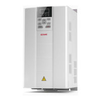
GTAKE GK600E-4T11B User Manual (128 pages)
Dedicated AC Motor Drives for Elevator and Hoist, 3AC 380-480V 3.7-30kW, GK600E Series
Brand:
GTAKE
| Category:
Controller
| Size: 8 MB
Table of Contents
Table of Contents
3
Chapter 1 Safety Precautions
6
Installation
6
Safety Considerations
6
Wiring
7
Run
8
Maintenance
9
Input Power Supply
10
Operation of Contactor
10
Other Considerations
10
Output Filter
10
Surge Protection
10
Derating
11
Insulation of the Motor
11
Chapter 2 Product Information
12
Model Explanation
12
Information of Product Model
13
Technical Features of GK600E
13
Product View and Parts Identification
16
Parts Drawing
16
Appearance, Mounting Dimensions and Weight
17
External Dimensions of Control Panel Bracket
18
Installation Environment
20
Minimum Mounting Clearances
20
Nameplate Information
12
Chapter 3 Installation and Wiring
20
Remove & Mount Control Panel and Cover
21
Open & Mount the Covers
22
Mount the Upper Cover
24
Mount the Lower Cover
24
Mount the Control Panel
24
Standard Configuration of Peripheral Devices
26
Instructions for Peripheral Devices
27
Terminal Configuration
29
Main Circuit Terminals and Wiring
29
Control Terminal Wiring
31
Terminal Screw and Wiring Requirement
31
Control Board Diagram
33
Wiring Diagram
34
Control Terminal Specification
35
Control Terminal Usage
36
Lay-Out of Control Terminals
36
Control Terminal Screw and Wiring Requirement
36
Instructions of Analog Input/Output Terminals
36
Instructions of Digital Input/Output Terminals
37
Internal Power Supply Dry Contact
37
External Power Supply Dry Contact
38
Open Collector NPN Connection
39
Open Collector PNP Connection
40
Instruction of Signal Switches
42
EMI Solutions
42
Noise Abatement
42
Jumper Diagram of Signal Switching
42
Grounding
43
Leakage Current Suppression
44
Use of Power Supply Filter
44
Operation of Control Panel
45
Key Functions on Control Panel
45
Chapter 4 Operation and Run Instructions
45
Control Panel Indicators
46
MF Key Function Definition
46
Control Panel Display Status
47
Display of Stop Parameters
47
Fault Alarm Display Status
48
Run Parameter Display Status
48
Parameter Edit Status
49
Direct Frequency Modification Status
50
Parameter Value Setting Status
50
Password Authentication Status
50
Prompt Characters
51
Prompt Message Status
51
Meanings of Displayed Characters
52
Parameter Display Structure
53
Parameter System
53
Setting Method of Parameters
53
Example of Setting of Parameter
54
First-Tier Display of Parameter
54
Second-Tier Display of Parameter
54
Clear Password
55
Flow Chart of User Password Setting
55
Password Authentication
55
Example of Parameter Setting
56
Flow Chart of Upper Limit Frequency Modification
56
Corresponding Relation between Binary and Hexadecimal
57
Flow Chart of User Parameter Initialization
57
Lock/Unlock Control Panel
58
Setting of Hexadecimal Parameter L1-02
58
Standard Wiring
60
Chapter 5 Elevator Dedicated Parameters
60
Elevator Sequence
61
Startup Manual
62
System Parameters
62
Setting of Password
62
Change Password
62
Parameter Restoration
63
Run Command
63
Binding of Run Command and Frequency Set
63
Run Direction
64
Start Method
64
Start Frequency
64
Holding Time of Start Frequency
65
DC Brake Start Current/DC Brake Start Time
65
Stop Method
65
Start Frequency of DC Brake Stop/DC Injection Brake Current at Stop
65
Dynamic Brake
66
Dynamic Brake Threshold Voltage
66
S-Curve Linear Acc/Dec Time / Smooth Start Acc Time
66
Digital Input
67
Accel/Decel Curve
67
S-Curve Acc Start/End Time
67
S-Curve Dec Start Time/S-Curve Dec End Time
67
Digital Output
68
Motor Parameters
68
Motor V/F Control Parameters
70
No Motor Auto-Tune
70
Static Motor Auto-Tune
70
Rotary Motor Auto-Tune
70
Broken Line V/F
71
V/F Separated Pattern
71
Enhanced Function
73
Switching FREQ
73
Protection Parameters
74
Overvoltage Stall
74
Overload Alarm
74
Overload Alarm Threshold
75
Overload Alarm Activation Time
75
Cooling Fan Control
75
Drive Overheat Alarm Threshold
75
Elevator Control Mode
76
Lift Control Mode
76
Brake Open Frequency
77
Brake Open Current
77
Chapter 6 List of Parameters
80
System Parameters and Parameter Management
81
User-Defined Display Parameters
82
Frequency Setting
83
Run Parameter Setting
83
Start/Stop Control
84
Accel/Decel Parameters
86
Input and Output Terminals
87
Analog and Pulse Output
93
Automatic Correction of Analog Input
94
Motor and Control Parameters
95
V/F Control Parameters
96
Vector Control Parameters
97
Enhanced Function and Protection Parameters
98
Application
102
Multi-Step Frequency
102
Lift Dedicated Parameters
103
MODBUS Communication Parameters
103
Keys and Display of Control Panel
104
Control Panel Display Setting
105
Status Monitoring
107
History Fault
110
Chapter 7 Troubleshooting
113
Fault Causes and Troubleshooting
113
Routine Inspection
122
Table of Fault Codes
113
Chapter 8 Maintenance
122
Regular Maintenance
123
Replacement of Vulnerable Parts
124
Storage
125
Advertisement
Advertisement
Related Products
GTAKE GK600E-4T5.5B
GTAKE GK600E-4T3.7B
GTAKE GK600E-4T18.5B
GTAKE GK600E-4T22B
GTAKE GK600E-4T30B
GTAKE GK600E-4T7.5B
GTAKE GK600E-4T15B
GTAKE GK500-2T0.75B
GTAKE GK500-4T0.75B
GTAKE GK500-4T2.2B
GTAKE Categories
DC Drives
Controller
Network Hardware
More GTAKE Manuals
Login
Sign In
OR
Sign in with Facebook
Sign in with Google
Upload manual
Upload from disk
Upload from URL