Sign In
Upload
Manuals
Brands
GTAKE Manuals
Controller
GK500-4T2.2B
GTAKE GK500-4T2.2B Manuals
Manuals and User Guides for GTAKE GK500-4T2.2B. We have
1
GTAKE GK500-4T2.2B manual available for free PDF download: User Manual
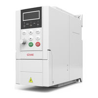
GTAKE GK500-4T2.2B User Manual (84 pages)
Mini AC Motor Drives
Brand:
GTAKE
| Category:
Controller
| Size: 3 MB
Table of Contents
Important Notes
2
Preface
2
Summary of Changes
3
Table of Contents
4
Chapter 1 Safety Precautions
6
Prior to Installation
6
Safety Considerations
6
Safety Signs in this Manual
6
Wiring
7
Run
8
Maintenance
9
Input Power Supply
10
Operation of Contactor
10
Other Considerations
10
Surge Protection
10
Derating
11
Insulation of the Motor
11
Model Explanation
12
Nameplate Information
12
Chapter 2 Product Information
12
Information of Product Model
13
Product Model and Technical Data
13
Technical Features of GK500
13
Parts Drawing
16
Configuration, Mounting Dimensions and Weight
16
External Dimensions
16
Dimensions and Weight
17
External Dimensions of Control Panel
17
Cabinet Hole Dimensions When Control Panel Remote Mounting Required
18
Installation Environment
19
Minimum Mounting Clearances
19
Chapter 3 Installation and Wiring
19
Remove & Mount the Control Panel and Cover
20
Remove Control Panel
20
Mount Control Panel
20
Open the Cover
20
Selection of Peripheral Devices
21
Open and Close the Cover
21
Terminal Configuration
22
Main Circuit Terminals and Wiring
22
Main Circuit Terminals
23
Terminal Screw and Wiring Requirement
23
Control Terminal Wiring
24
Control Terminal Specification
26
Control Terminal Usage
27
Lay-Out of Control Terminals
27
Control Terminal Screw and Wiring Requirement
27
Instructions of Analog Input/Output Terminals
27
Instructions of Digital Input/Output Terminals
28
Instructions of Digital Input Terminal
28
Dry Contact
28
Dry Contact Wiring
28
Open Collector
29
Open Collector NPN Wiring
29
Dry Contact Wiring (Activated at X-Terminal High Level)
29
Instructions of Digital Output Terminal
30
Instructions of y Output Terminal
30
Open Collector PNP Wiring
30
Wiring When y Output with Pull-Up Resistor
30
Instruction of Signal Switches
31
EMI Solutions
31
Diagram of Signal Jumper Switches
31
Wiring Instruction of Relay Output Terminal
31
Noise Abatement
32
Grounding
32
Leakage Current Suppression
33
Use of Power Supply Filter
33
Instructions During the Use
34
Operation of Control Panel
35
Key Functions
35
Key and Potentiometer Functions on Control Panel
35
Chapter 4 Operation and Run Instructions
35
Control Panel Indicators
36
Description of Indicators
36
Potentiometer Setting
37
Prompt Message Status
37
Parameter Setting
38
Parameter Display Structure
38
First-Tier Parameter Display
38
Second-Tier Parameter Display
38
Chapter 5 List of Parameters
39
FWD/REV Terminal Control
64
Three-Wire Mode
64
Two-Wire Mode
64
FDT1 Upper Bound
65
Analog Input Curve Selection
66
FDT1 Lower Bound
66
AO Gain
68
AO Offset
68
Voltage Input
68
Analog Corrected Channel
69
Diagram of Influence of AO Gain on Output
69
Diagram of Influence of AO Offset on Output
69
Chapter 6 Troubleshooting
71
Fault Causes and Troubleshooting
71
Routine Inspection
78
Table of Fault Codes
71
Chapter 7 Maintenance
78
Regular Maintenance
79
Replacement of Vulnerable Parts
80
Storage
81
Advertisement
Advertisement
Related Products
GTAKE GK500-2T0.4B
GTAKE GK500 Series
GTAKE GK500-2T0.75B
GTAKE GK500-4T0.75B
GTAKE GK500-4T1.5B
GTAKE GK500-2T1.5B
GTAKE GK500-4T3.7B
GTAKE GK500-2T2.2B
GTAKE GK600E-4T3.7B
GTAKE GK600E-4T22B
GTAKE Categories
DC Drives
Controller
Network Hardware
More GTAKE Manuals
Login
Sign In
OR
Sign in with Facebook
Sign in with Google
Upload manual
Upload from disk
Upload from URL