Sign In
Upload
Manuals
Brands
Gree Manuals
Air Conditioner
GWH09QD-S6DBC2A/I
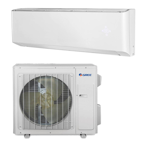
Gree GWH09QD-S6DBC2A/I Manuals
Manuals and User Guides for Gree GWH09QD-S6DBC2A/I. We have
1
Gree GWH09QD-S6DBC2A/I manual available for free PDF download: Service Manual
Gree GWH09QD-S6DBC2A/I Service Manual (124 pages)
Brand:
Gree
| Category:
Air Conditioner
| Size: 39.04 MB
Table of Contents
Table of Contents
2
Part Ⅰ : Technical Information
4
Models List
5
Outdoor Unit
5
Specification Sheet
6
Capacity Variation Ratio According to Temperature
16
Cooling
16
Heating
16
Cooling and Heating Data Sheet in Rated Frequency
17
Compressor Frequency(Hz)
18
Indoor Fan Motor Rotating Speed
18
Noise Curve
18
1 Summary
4
Indoor Unit
4
3 Outline Dimension Diagram
19
Indoor Unit
19
Outdoor Unit
20
4 Refrigerant System Diagram
21
Cooling & Heating Model
21
5 Electrical Part
22
Wiring Diagram
22
Instruction
22
PCB Printed Diagram
26
Top View
26
Bottom View
26
6 Function and Control
30
Remote Controller Introduction for YAG1FB3(Wifi)
30
Buttons on Remote Controller
30
Introduction for Icons on Display Screen
30
FAN Button
31
MODE Button
31
Turbo Button
31
Timer On/Timer off Button
32
Temp Button
32
I FEEL Button
32
Light Button
32
Introduction for Special Function
33
About AUTO RUN
33
About Turbo Function
33
About Lock
33
Operation Guide
34
General Operation
34
Optional Operation
34
Replacement of Batteries in Remote Controller
34
Remote Controller Introduction for YAG1FB2(Wifi)
35
GREE+ App Operation Manual
40
Control Flow Chart
40
Operating Systems
40
Download and Installation
40
Ewpe Smart App Operation Manual
41
Brief Description of Modes and Functions
42
Temperature Parameters
42
Basic Functions
42
Cooling Mode
42
Condition and Process of Defrost
43
Protection
43
Cold Air Prevention
43
Operation Way of AUTO Mode
43
Overload Protection
44
Faults of Temperature Sensors
44
DC Bus Voltage Protection
44
Module Protection
44
In Cooling Mode
45
In Heating Mode
45
Indoor Fan Control
45
Buzzer Control
46
Auto Button
46
Up-And-Down Swinging Control
46
Operation Pattern and Mode Pattern Display
46
Safety Precautions
47
Electrical Safety Precautions
47
Part Ⅱ : Installation and Maintenance
47
7 Notes for Installation and Maintenance
47
Safety Precautions for Installing and Relocating the Unit
48
Safety Precautions for Refrigerant
48
Installation Notes
49
Maintenance Notes
49
Qualification Requirement for Installation and Maintenance man
49
Safety Operation of Flammable Refrigerant
49
Main Tools for Installation and Maintenance
50
Installation Dimension Diagram
51
Installation Procedures
52
Start Installation
52
Installation of Indoor Unit
53
Installation Parts-Checking
53
Requirements for Electric Connection
53
Selection of Installation Location
53
Connect the Pipe of Indoor Unit
54
Install Drain Hose
54
Install Wall-Mounting Frame
54
Outlet Pipe
54
Bind up Pipe
55
Connect Wire of Indoor Unit
55
Hang the Indoor Unit
55
Connect Outdoor Electric Wire
56
Fix the Support of Outdoor Unit
56
Install Drain Joint
56
Installation of Outdoor Unit
56
Check after Installation and Test Operation
57
Leakage Detection
57
Use Vacuum Pump
57
Vacuum Pumping and Leak Detection
57
9 Maintenance
58
Error Code List
58
Procedure of Troubleshooting
64
Malfunction of Temperature Sensor F1, F2
64
Malfunction of Blocked Protection of IDU Fan Motor H6
65
Malfunction of Protection of Jumper Cap C5
66
Malfunction of Overcurrent Protection E5
67
Communication Malfunction E6
68
Malfunction of Detecting Plate(WIFI) JF
70
High Temperature and Overload Protection (E8)
73
Start-Up Failure (LC)
74
Overload and High Discharge Temperature Malfunction
75
Main Detection Points
75
H3 or E4 Is Displayed
76
Communication Malfunction (E6)
77
Maintenance Method for Normal Malfunction
78
Air Conditioner Cant be Started up
78
Poor Cooling (Heating) for Air Conditioner
78
Horizontal Louver Cant Swing
78
ODU Fan Motor Cant Operate
79
Compressor Cant Operate
79
Air Conditioner Is Leaking
79
Abnormal Sound and Vibration
79
10 Exploded View and Parts List
80
Indoor Unit
80
Qd
82
Qe
88
Outdoor Unit
93
Removal Procedure of Indoor Unit
98
Remove Filter Assembly
98
Remove Horizontal Louver
98
Remove Electric Box Cover 2 and Detecting Plate(WIFI)
99
Remove Front Case Sub-Assy
99
Remove Vertical Louver
99
Remove Electric Box Assy
100
Remove Evaporator Assy
101
Remote Motor and Cross Flow Blade
102
Remove Filter Assy
103
Remove Panel and Display
103
Removal Procedure of Outdoor Unit
108
Before Disassembly
108
Remove Top Cover
108
Remove Handle and Valve Cover
108
Remove Panel and Grille
109
Remove Cross Fan Blade
109
Remove Motor
110
Remove Motor Support
110
Remove Right Side Plate
110
Remove Four-Way Valve Assy
111
Remove Electron Expansion Valve
111
Remove Compressor
112
Remove Big and Small Valve Assy
112
Remove Handle
113
Remove Top Panel
113
Remove Front Side Panel
113
Remove Grille and Panel
114
Remove Axial Flow Blade
114
Remove Moto
114
Remove4-Wayvalve Assy
116
Remove Electronic Expansion Valv
116
Remove Valve Support and Cut off Valve
116
Set Temperature
118
Ambient Temperature
118
Appendix
118
Appendix 1: Reference Sheet of Celsius and Fahrenheit
118
Appendix 2: Configuration of Connection Pipe
118
Cut the Pip
119
Remove the Burrs
119
Expand the Port
119
Appendix 3: Pipe Expanding Method
119
Resistance Table of Ambient Temperature Sensor for Indoor and Outdoor
120
Appendix 4: List of Resistance for Temperature Sensor
120
Advertisement
Advertisement
Related Products
Gree GWH09QD-S6DBD2A/I
Gree GWH09QD-S6DBE4A/I
Gree GWH09QD-S6DBE6A/I
Gree GWH09QD-S6DBD6A/I
Gree GWH09QB-K3DNC4G
Gree GWH09QB-K6DNC4E/I
Gree GWH09QB-K6DNB2E/I
Gree GWH09QA-K6DNB4A/I
Gree GWH09QA-K6DNB4A
Gree GWH09QB-K3DNB4G/I
Gree Categories
Air Conditioner
Heat Pump
Dehumidifier
Controller
Chiller
More Gree Manuals
Login
Sign In
OR
Sign in with Facebook
Sign in with Google
Upload manual
Upload from disk
Upload from URL