Sign In
Upload
Manuals
Brands
Generac Power Systems Manuals
Portable Generator
CorePower 6/7 kW
Generac Power Systems CorePower 6/7 kW Manuals
Manuals and User Guides for Generac Power Systems CorePower 6/7 kW. We have
2
Generac Power Systems CorePower 6/7 kW manuals available for free PDF download: Diagnostic Repair Manual, Repair Manual
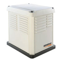
Generac Power Systems CorePower 6/7 kW Diagnostic Repair Manual (152 pages)
Home Standby Generator
Brand:
Generac Power Systems
| Category:
Portable Generator
| Size: 13 MB
Table of Contents
Read this Manual Thoroughly
2
Replacement Parts
2
Table of Contents
3
Specifications
6
Generator
6
Engine
6
Fuel Consumption
7
Major Features - Corepower
7
Major Features - Powerpact
7
Interconnections - Corepower
8
Interconnections - Powerpact (60 Hz)
9
Interconnections - Powerpact (50 Hz)
10
Part 1 - General Information
11
Section 1.1 - Generator Basics
12
Introduction
12
Parts
12
Generator Identification
12
Section 1.2 - Measuring Electricity
13
Meters
13
The vom
13
Measuring AC Voltage
13
Measuring DC Voltage
13
Measuring AC Frequency
13
Measuring Current
14
Measuring Resistance
14
Electrical Units
15
Ohm's Law
15
Section 1.3 - Preparation before Use
16
Introduction
16
Fuel Consumption
16
Reconfigure the Fuel System
16
Section 1.4 - Operating Instructions
18
Control Panel
18
Before Initial Start-Up
18
Generator Activation
18
User Interface
19
Automatic Operation
19
Manual Operation
19
Shutting Generator down While under Load
20
Section 1.5 - Automatic Operating Parameters
21
Introduction
21
Utility Failure
21
Cranking
21
Cranking Conditions
21
Load Transfer Parameters
22
Cold Smart Start
22
Section 1.6 - General Maintenance
23
Introduction
23
Engine Oil
23
Engine Oil Recommendations
23
Air Filter
23
Spark Plugs
23
Visual Inspection
23
Corrosion Protection
23
Valve Clearance
23
Battery
24
Service Schedule - Corepower
24
Service Schedule - Powerpact
25
Section 1.7 - General Troubleshooting
26
Introduction
26
Recommended Tools
26
Troubleshooting Reminders and Tips
26
Connectors
26
Part 2 - AC Generators
27
Section 2.1 - Description and Components
28
Introduction
28
Engine-Generator Drive System
28
Alternator Assembly
28
Brush Holder and Brushes
29
Other AC Generator Components
29
Section 2.1 - Description and Components
29
Section 2.2 - Operational Analysis
30
On-Speed Operation
30
Field Excitation
30
Startup
30
AC Power Winding Output
30
Voltage Regulator
30
Section 2.3 - Troubleshooting Flowcharts
31
Introduction
31
Problem 1 - Generator Produces Zero Voltage or Residual Voltage
31
Problem 2 - Generator Produces Low Voltage at No-Load Problem 2 - Generator Produces Low Voltage at No-Load
32
At No-Load
32
Problem 3 - Generator Produces High Voltage
33
At No-Load
33
Problem 4 - Voltage and Frequency Drop Excessively When Loads Are Applied Problem 4 - Voltage and Frequency Drop Excessively When Loads Are Applied
33
Excessively When Loads Are Applied
33
Section 2.4 - Diagnostic Tests
34
Introduction
34
Safety
34
AC Troubleshooting
34
Test 1 - Check Main Circuit Breaker
34
Test 4 - Fixed Excitation /Rotor Amp Draw Test
34
Test 6 - Resistance Check of Rotor and Rotor Circuit
37
Test 7 - Check Brushes and Slip Rings
37
Test 9 - Test the Stator
37
Test 11 - Check AC Output Voltage
39
Test 12 - Check AC Output Frequency
40
Test 13 - Check and Adjust Engine Governor
40
Test 14 - Adjust Voltage Regulator
41
Test 15 - Check for Overload Condition
42
Test 16 - Check Voltage and Frequency under Load
42
Part 3 - Transfer Switch
43
Section 3.1 - Description and Components
44
General
44
Enclosure
44
EZ Transfer Operator (Genready Switch Only)
44
Fuse Holder
44
Load Management Options
44
Smart Management Module (SMM)
44
Understanding the Smart Management Module
45
Setting Priorities
46
Tests
46
Troubleshooting
47
Section 3.2 - Operational Analysis
48
Utility Voltage Present
48
Transfer to Standby
48
Transfer to Utility
48
Section 3.3 - Troubleshooting Flowcharts
49
Introduction
49
Problem 10 - in Automatic Mode, no Transfer to Standby Problem 10 - in Automatic Mode, no Transfer to Standby
49
Generator Transfers to Standby During Exercise or in Manual Mode
49
No Transfer to Standby
49
Problem 11- in Automatic Mode, Generator
49
Problem 12 - Blown F1 or F2 Fuse
50
Problem 13 - Blown T1 Fuse
50
Utility Power Is on
50
(SMM) LED Is Off, Load Not Powered
50
Smm Problem 2 - Load Management Module
51
(SMM) LED Is On, Load Not Powered
51
Smm Problem 3 - Load Management Module
51
(SMM) LED Is Flashing, Load Not Powered
51
Smm Problem 4 - Load Management Module
51
(SMM) Is Humming or Buzzing
51
Section 3.4 - Diagnostic Tests
52
Introduction
52
Safety
52
Transfer Switch Troubleshooting
52
Test 26 - Check Manual Transfer Switch Operation
52
Test 27 - Check Generator Voltage at Transfer Switch
53
Test 28 - Test Transfer Operator
53
(Genready Switch Only)
53
Test 29 - Check 15B/194 Circuit
53
Test 30 - Check Wire 23 Circuit
53
Test 32 - Check Fuses F1 and F2
54
Test 33 - Check N1 and N2 Wiring
55
Test 35 - Check Fuse F3
55
Test 36 - Check T1 Wiring (60 Hz)
55
Test 36A - Check T1 and T2 Wiring (50 Hz)
55
Test 37 - Test SMM Contactor
56
Line, Load and Control
56
Test 38 - Check N1 and N2 Voltage
56
Test Points
56
Test 39 - Check Utility Sense Voltage
56
Test 40 - Check Utility Voltage at Transfer Switch
57
Test 41 - Check Utility Sensing Voltage
57
At the Controller
57
Part 4 - Engine/DC Control
61
Section 4.1 - Description and Components
62
General
62
Terminal Strip / Interconnection Terminal
62
(Corepower Only)
62
Controller
62
Auto-Off-Manual Control
62
7.5 Amp Fuse
62
Battery Charger (Corepower Only)
62
Section 4.2 - Engine Protective Devices
65
Alarms
65
Clear Alarms
65
Warnings
65
Section 4.3 - Operational Analysis
66
Utility Source Available - Corepower
66
Utility Failure and Engine Cranking - Corepower
66
Utility Failure and Engine Running - Corepower
68
Utility Source Available - Powerpact
69
Utility Failure and Engine Cranking - Powerpact
70
Utility Failure and Engine Running - Powerpact
71
Section 4.4 - Troubleshooting Flowcharts
72
Problem 20 - Engine will Not Crank When
72
Utility Power Source Fails
72
Problem 21 - Engine will Not Crank When Controller Is Set to "MANUAL" Mode
72
Controller Is Set to "Manual" Mode
72
Problem 22 - Engine Cranks but Won't Start
73
Problem 23 - Engine Starts Hard and Runs Rough / Lacks Power / Backfires
74
Problem 24 - Shutdown Alarm/Fault Occurred
75
Problem 25 - 7.5 Amp Fuse (F1) Blown
76
Problem 26 - Generator will Not Exercise
76
Problem 27 - no Battery Charge
76
Section 4.5 - Diagnostic Tests
77
Introduction
77
Safety
77
Engine/DC Troubleshooting
77
Test 52 - Check Controller Switch Position
77
Test 53 - Try a Manual Start
78
Test 54 - Test Auto Operations
78
Test 55 - Check 7.5 Amp Fuse
78
Test 56 - Check Battery and Cables
79
Test 57 - Check Wire 56 Voltage
80
Test 58 - Test Starter Contactor
81
Test Point
81
Test 59 - Test Starter Motor
81
Test 60 - Check Fuel Supply and Pressure
82
Test 61 - Check Controller Wire 14 Output
83
Test 62 - Check Fuel Solenoid
83
Test 63 - Check Choke Solenoid
83
Test 64 - Check for Ignition Spark
84
Test 65 - Check Spark Plugs
85
Test 66 - Check Engine / Cylinder Leak down Test
85
Compression Test
85
Cylinder Leak down Test
86
Check Compression
86
Test 67 - Check Ignition Coil
86
(Corepower Only)
87
Test 68A - Check Oil Pressure Switch and Wire
88
Test 68B - Check Oil Level Switch and Wire
88
(Powerpact Only)
88
Test 69 - Check High Oil Temperature Switch
88
Test 70 - Check and Adjust Valves
89
Test 71 - Check Wire 18 Continuity
90
Test 72 - Test Exercise Function
90
Test 73 - Test Cranking and Running Circuits
90
Test 74 - Check Battery Charger Supply Voltage
91
(Corepower Only)
91
Test 76 - Check Battery Charger out Voltage
92
(Powerpact Only)
92
Test 78 - Check Wire 0/15B
92
(Corepower Only)
92
Only)
92
Test 79 - Check Shutdown Wire
93
Part 5 - Disassembly
95
Section 5.1 - Major Disassembly - Corepower
95
Section 5.2 - Major Disassembly - Powerpact
95
Section 5.3 - Exploded Views
108
Part 6 - Electrical Data
131
Wiring Diagram - Drawing 0H7182-C (Corepower)
132
Wiring Diagram
132
Electrical Schematic
133
Drawing 0H7182-C (Corepower)
133
Drawing 0K7328-C (60 Hz Powerpact 1 of 4)
134
Drawing 0K7328-C (60 Hz Powerpact 2 of 4)
135
Electrical Schematic - Drawing 0K7328-C (60 Hz Powerpact 3 of 4)
136
Electrical Schematic - Drawing 0K7328-C (60 Hz Powerpact 4 of 4)
137
Drawing 0K7876-D (50 Hz Powerpact 1 of 4)
138
Drawing 0K7876-D (50 Hz Powerpact 2 of 4)
139
Drawing 0K7876-D (50 Hz Powerpact 3 of 4)
140
Drawing 0K7876-D (50 Hz Powerpact 4 of 4)
141
Wiring Diagram
142
Drawing 0K5879-B (50 Amp Transfer Switch)
142
Electrical Schematic - Drawing 0K5881-B (50 Amp Transfer Switch)
144
Electrical Formulas
146
Appendix A - Supplemental Worksheets
147
Advertisement
Generac Power Systems CorePower 6/7 kW Repair Manual (116 pages)
Home Standby Generator
Brand:
Generac Power Systems
| Category:
Portable Generator
| Size: 9 MB
Table of Contents
Safety
2
Read this Manual Thoroughly
2
Table of Contents
3
Specifications
6
Generator
6
Engine
6
Fuel Consumption
7
Major Features
7
Part 1 - General Information
11
Section 1.1 - Generator Basics
12
Introduction
12
Parts
12
Generator Identification
12
Section 1.2 - Measuring Electricity
13
Meters
13
The vom
13
Measuring AC Voltage
13
Measuring DC Voltage
13
Measuring AC Frequency
13
Measuring Current
14
Measuring Resistance
14
Electrical Units
15
Ohm's Law
15
Section 1.3 - Preparation before Use
16
Introduction
16
Fuel Consumption
16
Reconfigure the Fuel System
16
Section 1.4 - Operating Instructions
18
Control Panel
18
User Interface
18
Automatic Operation
18
Manual Operation
18
Section 1.5 - Automatic Operating Parameters
20
Introduction
20
Utility Failure
20
Cranking
20
Cranking Conditions
20
Load Transfer Parameters
20
Section 1.6 - General Maintenance
22
Introduction
22
Engine Oil
22
Engine Oil Recommendations
22
Air Filter
22
Spark Plugs
22
Visual Inspection
22
Corrosion Protection
22
Valve Clearance
22
Battery
23
Section 1.7 - General Troubleshooting
24
Introduction
24
Recommended Tools
24
Troubleshooting Reminders and Tips
24
Connectors
24
PART 2 - AC Generators
25
Section 2.1 - Description and Components
26
Introduction
26
Engine-Generator Drive System
26
Alternator Assembly
26
Brush Holder and Brushes
26
Other AC Generator Components
27
Section 2.2 - Operational Analysis
28
Startup
28
On-Speed Operation
28
Field Excitation
28
AC Power Winding Output
28
Section 2.3 - Troubleshooting Flowcharts
29
Introduction
29
Problem 1 - Generator Produces Zero Voltage or Residual Voltage
29
Problem 2 - Generator Produces Low Voltage at No-Load
30
Problem 3 - Generator Produces High Voltage at No-Load
31
Problem 4 - Voltage and Frequency Drop Excessively When Loads Are Applied
31
Section 2.4 - Diagnostic Tests
32
Introduction
32
Safety
32
AC Troubleshooting
32
Test 1 - Check Main Circuit Breaker
32
Test 4 - Fixed Excitation /Rotor Amp Draw Test
32
Diagnostic Tests
33
Test 6 - Resistance Check of Rotor Circuit
34
Test 7 - Check Brushes and Slip Rings
34
Test 9 - Test the Stator
35
Test 10 - Test Rotor Assembly
36
Test 11 - Check AC Output Voltage
36
Test 12 - Check AC Output Frequency
36
Test 13 - Adjust Engine Governor
37
Test 14 - Adjust Voltage Regulator
37
Test 15 - Check for Overload Condition
38
Test 16 - Check Voltage and Frequency under Load
38
PART 3 - Transfer Switch
39
Section 3.1 - Description and Components
40
General
40
Enclosure
40
EZ Transfer Operator
40
Fuse Holder
40
Section 3.2 - Operational Analysis
41
Utility Voltage Present
41
Transfer to Standby
41
Transfer to Utility
41
Section 3.3 - Troubleshooting Flowcharts
43
Introduction
43
Problem 10 - in Automatic Mode, no Transfer to Standby
43
Problem 11 - in Automatic Mode, Generator
43
Shuts down When Utility Returns but There Is no
43
To Standby During Exercise or in Manual Mode
43
Problem 12 - Blown F1 or F2 Fuse
44
Problem 13 - Blown T1 Fuse
44
Problem 14 - Unit Starts and Transfer Occurs When Utility Power Is on
44
Section 3.4 - Diagnostic Tests
45
Introduction
45
Safety
45
Transfer Switch Troubleshooting
45
Test 27 - Check Generator Voltage at Transfer Switch
45
Test 28 - Test Transfer Operator
45
Test 29 - Check 15B/194 Circuit
45
Test 30 - Check Wire 23 Circuit
46
Test 32 - Check Fuses F1 and F2
46
Test 33 - Check N1 and N2 Wiring
47
Test 35 - Check Fuse F3
47
Test 36 - Check T1 Wiring
47
Test 38 - Check N1 and N2 Voltage
48
Test 39 - Check Utility Sense Voltage
48
Test 40 - Check Utility Voltage at Transfer Switch
48
Test 41 - Check Utility Sensing Voltage
48
At the Controller
48
PART 4 - Engine/DC Control
51
Section 4.1 - Description and Components
52
General
52
Terminal Strip / Interconnection Terminal
52
Controller
52
Auto-Off-Manual Switch
52
7.5 Amp Fuse
52
Alarms
54
Clear Alarms
54
Warnings
54
Section 4.3 - Operational Analysis
56
Utility Source Available
56
Utility Failure and Engine Cranking
57
Utility Failure and Engine Running
58
Section 4.4 - Troubleshooting Flowcharts
59
Problem 20 - Engine will Not Crank When Utility Power Source Fails
59
Problem 21 - Engine will Not Crank When AUTO-OFF-MANUAL Switch Is Set to "MANUAL
59
Problem 22 - Engine Cranks but Won't Start
60
Problem 23 - Engine Starts Hard and Runs Rough / Lacks Power / Backfires
61
Problem 24 - Shutdown Alarm/Fault Occurred
62
Problem 25 - 7.5 Amp Fuse (F1) Blown
63
Problem 26 - Generator will Not Exercise
63
Problem 27 - no Battery Charge
63
Section 4.5 - Diagnostic Tests
64
Introduction
64
Safety
64
Engine/DC Troubleshooting
64
Auto-Off-Manual Switch
64
Test 53 - Try a Manual Start
65
Test 54 - Test Auto Operations
65
Test 55 - Check 7.5 Amp Fuse
65
Test 56 - Check Battery
65
Test 57 - Check Wire 56 Voltage
67
Test 58 - Test Starter Contactor
67
Test 59 - Test Starter Motor
68
Test 60 - Check Fuel Supply and Pressure
69
Test 61 - Check Circuit Board Wire 14 Output
70
Test 62 - Check Fuel Solenoid
71
Test 63 - Check Choke Solenoid
71
Test 64 - Check for Ignition Spark
71
Test 65 - Check Spark Plugs
72
Test 66 - Check Engine / Cylinder Leak
73
Down Test / Compression Test
73
Cylinder Leak down Test
73
Check Compression
73
Test 67 - Check Ignition Coil
74
Test 68 - Check Oil Pressure Switch and Wire
74
Test 69 - Check High Oil Temperature Switch
75
Test 70 - Check and Adjust Valves
76
Test 71 - Check Wire 18 Continuity
77
Test 72 - Test Exercise Function
77
Test 73 - Test Cranking and Running Circuits
77
Test 74 - Test Run Circuit
78
Test 75 - Test Crank Circuit
78
Test 76 - Check Battery Charger Supply Voltage
78
Test 77 - Check Battery Charger Output Voltage
79
Test 78 - Check Wire 0/15B
79
Test 79 - Check Shutdown Wire
79
Wiring Diagram
104
Electrical Schematic
105
Electrical Formulas
106
Index of Figures
112
Index of Tables
113
Advertisement
Related Products
Generac Power Systems Guardian 6720
Generac Power Systems Guardian 6721
Generac Power Systems Guardian 6730
Generac Power Systems PowerPact 6/7.5 kW 60 Hz
Generac Power Systems PRIMEPACT 66G
Generac Power Systems 6500XL 09779-2
Generac Power Systems PowerPact 6518
Generac Power Systems Guardian 6439
Generac Power Systems Guardian 6459
Generac Power Systems 6872-3
Generac Power Systems Categories
Portable Generator
Inverter
Pressure Washer
Switch
Lighting Equipment
More Generac Power Systems Manuals
Login
Sign In
OR
Sign in with Facebook
Sign in with Google
Upload manual
Upload from disk
Upload from URL