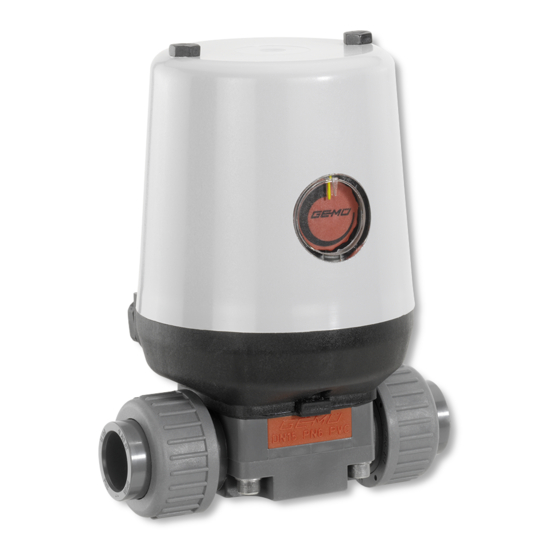
Sign In
Upload
Manuals
Brands
GEMÜ Manuals
Control Unit
613
GEMÜ 613 Manuals
Manuals and User Guides for GEMÜ 613. We have
1
GEMÜ 613 manual available for free PDF download: Installation, Operating And Maintenance Instructions
GEMÜ 613 Installation, Operating And Maintenance Instructions (64 pages)
Motorized Diaphragm Valves, Metal/Plastic, DN 4-20
Brand:
GEMÜ
| Category:
Control Unit
| Size: 1.1 MB
Table of Contents
Deutsch
2
Allgemeine Hinweise
2
Table of Contents
2
Allgemeine Sicherheitshinweise
3
Hinweise für Service
3
Und Bedienpersonal
3
Warnhinweise
3
Begriffsbestimmungen
4
Verwendete Symbole
4
Vorgesehener Einsatzbereich
4
Auslieferungszustand
4
Technische Daten GEMÜ
5
Bestelldaten
7
Bestelldaten GEMÜ
7
Benötigtes Werkzeug
10
Herstellerangaben
10
Lagerung
10
Lieferung und Leistung
10
Transport
10
Ausführungen
11
Funktionsbeschreibung
10
Geräteaufbau
12
Montage des Ventils
12
Montage, Bedienung und Einstellung
12
Bedienung und Einstellung
15
Elektrische Schließbegrenzung für E1 / E2 → Stellung des Ventils bei Sollwert 0 V Bzw. 0 / 4 Ma Neu Programmieren
16
Elektrische Öffnungsbegrenzung für E1 / E2 → Stellung des Ventils bei Sollwert 20 Ma Neu Programmieren
16
RESET - Sollwerteingang in die Werkseinstellung Zurücksetzen für
16
11.2.4 Einstellung der Totzone
17
Anschlusspläne
17
Elektrische Anschlüsse
17
Internes Schaltbild mit Anschluss auf Klemmleiste
17
Optische Stellungsanzeige
17
Vorgehensweise
17
Demontage Membrane
20
Demontage Ventil (Antrieb vom Körper Lösen)
20
Montage / Demontage von Ersatzteilen
20
Montage Membrane
20
13.3.2 Montage der Konkav-Membrane
21
Dichtheit des Ventils Prüfen
22
Inbetriebnahme
23
Montage Antrieb auf Ventilkörper
22
Inspektion und Wartung
23
Demontage
24
Entsorgung
24
Rücksendung
24
Hinweise
24
20 Fehlersuche /
26
Schnittbilder und Ersatzteile
26
Störungsbehebung
28
Einbauerklärung
28
EG-Konformitätserklärung
29
English
32
General Information
33
General Safety Information
33
Information for Service and Operating Personnel
33
Warning Notes
33
Definition of Terms
34
Intended Area of Use
34
Symbols Used
34
Condition as Supplied to Customer
34
Technical Data GEMÜ
35
Order Data
37
Order Data GEMÜ
37
Delivery and Performance
40
Manufacturer's Information
40
Storage
40
Tools Required
40
Transport
40
Versions
41
Functional Description
40
Construction
42
Installation, Operation and Adjustments
42
Installing the Valve
42
Operation and Adjustments
45
Electric Closing Limit for
46
Reprogramming Position of Valve at Set Value 0 V or 0 / 4 Ma
46
Electric Opening Limit for
46
Reprogramming Position of Valve
46
RESET Set Value Input to Factory Setting for
46
11.2.4 Setting the Dead Zone
47
Connection Diagrams
47
Electrical Connections
47
Internal Wiring Diagram with Connection to Terminal Strip
47
Optical Position Indicator
47
Procedure
47
13.3.1 General Information
50
Assembly / Disassembly of Spare Parts
50
Mounting the Diaphragm
50
Removing the Diaphragm
50
Valve Disassembly (Removing Actuator from Body)
50
13.3.2 Mounting a Concave Diaphragm
51
Actuator Mounting on Valve Body
52
Checking the Valve Seal
52
Commissioning
53
Inspection and Servicing
53
Disassembly
54
Disposal
54
Returns
54
Information
54
Fault Clearance
55
20 Troubleshooting /
55
Sectional Drawings and Spare
56
Declaration of Incorporation
58
EC Declaration of Conformity
59
Manufacturer's Declaration
60
Advertisement
Advertisement
Related Products
GEMÜ 618
GEM 615
GEM 612 Series
GEM 617
GEM 611
GEM 610
GEM 616
GEM 687
GEM 625
GEM eSyStep 639 AE Series
GEMÜ Categories
Control Unit
TV Mount
Measuring Instruments
Valve Positioners
Accessories
More GEMÜ Manuals
Login
Sign In
OR
Sign in with Facebook
Sign in with Google
Upload manual
Upload from disk
Upload from URL