Sign In
Upload
Manuals
Brands
GEDA Manuals
Industrial Equipment
300 ZP 2
GEDA 300 ZP 2 Manuals
Manuals and User Guides for GEDA 300 ZP 2. We have
2
GEDA 300 ZP 2 manuals available for free PDF download: Operating Manual
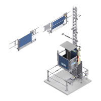
GEDA 300 ZP 2 Operating Manual (101 pages)
Construction Hoist / Transport Platform For loads and persons
Brand:
GEDA
| Category:
Lifting Systems
| Size: 2 MB
Table of Contents
Table of Contents
3
Guide
7
Images
7
Warning Notices
7
Overview of Warnings in the Manual
8
Electric Shock
8
Crushing by Car
8
Do Not Use the Hoist in the Event of Fire
8
Reaching into the Travel Path During Operation
8
Secure Machine against Being Switched on
9
Falling Tools / Parts
9
Fall and Trip Hazard
9
Suspended Loads
9
Prevent Access for Unauthorised Persons
9
Wear Safety Clothing
10
Abbreviations
11
Imprint
11
Identification Data
12
Machine
12
Manufacturer
12
Geda Representatives
13
Ordering Spare Parts
13
Technical Data
14
Speeds
14
Drives
14
Assembly Height
14
Emissions
14
Dimensions and Weight
15
Base Unit / Platform / Cable Box
15
Mast Section
15
Landing-Level Safety Gates
15
Mast
16
Inclination of Mast
16
Technical Information on Assembly
16
Foundation
16
Soil Pressure
16
Tightening Torques
17
Mechanical Screw Connections Without Torque Control
17
Mechanical Screw Connections with Torque Control
17
Electrical Screw Connections (Metal Screw Connections)
17
Safety Distance from Live Wires
17
European Wind Regions
18
Assembly Geometry
19
Anchoring Forces
22
Stiffener Tubes
24
Operating Materials
25
Electrics
25
Tests
26
Operating and Environmental Conditions
26
Safety Information
27
Proper Use
27
Machine Limits
27
Modifications / Alterations
27
Linking to Other Machinery
28
Prohibition of Certain Activities
28
Machine Operation
28
Foreseeable Misuse
28
Machine Hazards
29
Hazard Sources / Existing Residual Hazards
29
Moving, Rotating, Pointed and Sharp-Edged Parts
29
Energies
29
Operating Materials
29
Emergency
29
Other Relevant Documents
30
Export Licence
30
Warranty
30
Geda Training Sessions
30
Obligations of the Operating Company
31
Obligation of Training / Qualification
31
Accessibility to Necessary Information
32
Checking the Correct and Proper Condition and Use
32
Identifying Hazards at the Place of Use
32
Machines / Systems Requiring Registration
32
Recurring Inspections
32
Transporting Suspended Loads over the Machine
33
Preparing an Emergency / Evacuation Plan
33
Training Assembly Engineers from Other Companies
33
Following the Instructions of Geda Assembly Engineers
33
Provision of Personal Protective Equipment
33
Regarding Use by Authorised People
34
Operator
34
Attendant / Platform Operator
34
Professionals for Maintenance / Servicing
34
Protection of Particular Groups of People
34
Young People, Pregnant Women, Disabled Persons
34
People with Pacemakers and Metal Implants
34
Obligatory Safety Instructions
35
Basic Conduct When Working with the Machine
35
Transporting the Machine / Disposing of the Machine
36
Set-Up and Connection / Installation
37
First Commissioning / Daily Commissioning
38
Transporting People
39
Transporting Material
40
Servicing / Repairs / Maintenance / Work on Electrical Components
41
Cleaning
42
Conduct in an Emergency
42
Hazard Area Can be Left
43
Hazard Area Cannot be Left
43
Supplementary Safety Instructions - Components from Other Manufacturers
43
Brief Description of the Machine
44
Operating and Control Elements
46
Master Switch
46
Car Control
46
Manual Control
47
Overload Control Lamp and Socket Outlet
47
Ground Station Car Access Ramp
48
Building Car Access Ramp
49
Drop-Test Control Unit
50
Safety and Emergency Equipment
51
Emergency Stop
52
Triggering an EMERGENCY STOP / Machine Shut-Down in Events of Emergency
52
Ending the Emergency Stop Situation
52
Defect after an Emergency Stop Situation
52
Location of the Emergency Stop Buttons
53
Safety Stop
54
Safety Gear
54
Emergency Limit Switch
54
Emergency Lowering (Brake Release Lever)
55
Country-Specific Equipment Variants / Accessories
56
Collision Grille
56
Roof
56
Assembly Bridge
57
Replace the Cable Box
57
Converting Access to the Front End / Adding a Second Access
58
Enclosure with Barrier
59
Holder for Individual Support Frames
60
Cold Package
60
Operating Time Indicator
60
Daily Inspections before Starting Work
61
Visual Inspections
61
Function Tests
62
Test Run with an Empty Car
62
Test Run by Platform Operator / Person Authorised to Carry out Tests and Inspections
62
Rescuing People Trapped Inside
63
Basic Conduct in the Event of a Rescue / Malfunction
63
Rescue Measures Plan
64
Rescuing People from the Car
65
Cleaning
66
Cleaning the Machine Inside and out
66
Cleaning the Area Around the Machine
66
Assembly
67
Transport to the Assembly Location
69
Assembly Plan
70
Assembling the Base Unit
71
Mounting the First Mast Tie
71
Transport through Narrow Spaces
72
Dismantling the Accesses
73
Dismantling the Front Wall
74
Folding up the Car
74
Remove Protective Buffers
75
Unscrew Foot Section
75
Installation at the Assembly Location
75
Inspection after Assembly
75
Assembly / Anchoring of the Mast
76
Assembling the Mast Fixture
77
Trailing Cable Guide
78
Using the Assembly Bridge
79
Assembling the EMERGENCY Limit Switch Bar
80
Landing-Level Limit Switch Bar
80
Securing Loading and Unloading Points
80
Checks after Assembly / Checks Prior to Initial Commissioning
81
Disassembly
81
Disposing of the Machine
81
Maintenance
82
Warnings and Safety Instructions to be Complied with During Maintenance / Servicing
82
Maintenance Plan
83
Visual Inspections
85
Test Run with an Empty Car
86
Test Run by Platform Operator / Person Authorised to Carry out Tests and Inspections
86
Refilling and Inspection Jobs
87
Lubrication Device
87
Checking for Wear
88
Drive Pinion
88
Gear Rack
88
Tracks Rollers
89
Motor Brake
90
Function Tests
91
Safety Gear
91
Drop Test Passed
92
Drop Test Not Passed
92
Check Safety Gear for Damage
93
Safety Gear Replacement
93
Fault Table
94
Documenting the Checks
95
Advertisement
GEDA 300 ZP 2 Operating Manual (104 pages)
Construction Hoist/Transport Platform
Brand:
GEDA
| Category:
Industrial Equipment
| Size: 7 MB
Table of Contents
General Information 300 Z/ZP
2
Table of Contents
5
General Information
9
Information on the Operating Manual
9
Abbreviations
11
Identification Data
12
Manufacturer's Name and Address
13
Information about the Author and Industrial Property Rights
14
Patents
14
Instructions for the Operating Company
14
Intended Use
16
Assembly, Service/Maintenance Specialist
18
Operating Personnel
18
Improper Use
18
General Safety Information
19
Residual Risks
19
Safety Instructions for Operating Personnel
20
Safety Instructions for Transport
21
Safety Instructions for Operation
22
Safety Instructions for Maintenance and Troubleshooting
23
Safety When Working on the Electric System
25
Technical Data
26
Operating and Environmental Conditions
26
Emissions
27
Tightening Torques
27
Electrical Connected Loads
28
Speeds
30
Heights
30
Mast
31
Fig. 1: UNI-X-MAST
31
Fig. 2: UNI-Mast
31
Fig. 3: Anchor Diagram
32
Load Capacity, Dimensions and Weights
34
Platform a / B
34
Fig. 4: Platform a
34
Fig. 5: Platform B
34
Fig. 6: Required Space Platforms a and B
36
Operation
37
Safety During Operation
37
Special Safety Instructions for Operation as a Material Hoist
38
Special Safety Instructions for Operation as a Transport Platform
38
Commissioning
39
Fig. 7: Ground Station Switch Box
39
Fig. 8: Selector Switch for Operating Mode, Ready for Operation
39
Safety Check before Starting Work
40
Operation/Function
41
Fig. 9: Overview
41
Fig. 49: Roof
41
Securing the Lowest Stop Position (Ground Station)
42
Cordon
43
Fig. 10: Cordon
43
M Base Enclosure with Barrier (Option)
44
Fig. 11: 1.10 M Base Enclosure with Barrier
44
Sliding Door for 2.00 M Base Enclosure (Option)
45
Fig. 12: Sliding Door for Ground Base Enclosure
45
Fig. 13: Unlocking the Sliding Door Lock
46
Fig. 14: Opening the Sliding Door
46
Fig. 15: Closing the Sliding Door
46
Fig. 16: Sliding Door for Base Enclosure Open
47
Fig. 17: Emergency Release for Sliding Door from Outside
47
Fig. 18: Door Lock Unlocked
48
Fig. 19: Door Lock Locked
48
Platform Access at the Ground Station
49
Loading Door / Ramp
49
Fig. 20: Locking the Loading Door/Ramp
49
Fig. 21: Platform with Front Ramp
50
Fig. 22: Emergency Release for Ramp/Loading Door
51
Platform Access Landing Level
52
Fig. 23: Platform Access Landing Level
52
Barrier with Mechanical Lock
53
Fig. 24: Barrier with Mechanical Lock
53
Fig. 25: Opening Barrier with Mechanical Lock
53
Fig. 26: Closing Barrier with Mechanical Lock
54
Securing Loading and Unloading Points
55
Standard/Standard Basic" Landing Level Safety Gate
55
Fig. 27: Standard Landing Level Safety Gate No. 01217/01268
55
Fig. 28: "Standard" Landing Level Safety Gate Closed (Tarpaulin)
56
Fig. 29: Opening/Closing the "Standard" Landing Level Safety Gate
56
Comfort" Landing Level Safety Gate
57
Fig. 30: "Comfort" Landing Level Safety Gate No. 01212
57
Fig. 31: "Comfort" Landing Level Safety Gate Closed (Tarpaulin)
57
Fig. 32: "Comfort" Landing Level Safety Gate Closed (Filler Plate)
58
Fig. 33: Opening/Closing the "Comfort" Landing Level Safety Gate
58
VARIO" Landing Level Safety Gate
59
Fig. 34: "VARIO" Landing Level Safety Gate No. 68000
59
Fig. 35: Opening/Closing the "VARIO" Landing Level Safety Gate
59
Fig. 36: Emergency Unlocking of the Landing Level Door
60
Controls
61
Functional Description
61
Use as a Construction Hoist (External Control)
64
Fig. 37: Actuating the External Control
64
Fig. 38: Ground Control/Manual Control (Position I)
65
Fig. 39: Ground Control for Enclosure (MANUAL)
65
Fig. 40: Ground Control/Manual Control (Position II)
67
Fig. 41: Ground Control for Enclosure (AUTOMATIC)
67
Fig. 42: Electric Module for Landing Level Safety Gate
69
Operation as Transport Platform (Platform Control)
70
Fig. 43: Activating the Platform Control
70
Controls for Special Operation
73
Operation for Assembly
73
Fig. 44: Selector Switch for Operating Mode, Assembly
73
Fig. 45: Platform Control for Assembly
74
Drop Test Control
75
Fig. 46: Drop Test Control
75
Emergency Shutdown
76
Fig. 47: EMERGENCY STOP Button
76
Interrupting Work - End of Work
77
Fig. 48 Main Switch Secured
77
Equipment
78
Roofs
78
Assembly Plank
79
Fig. 50: Assembly Plank
79
Cable Protection
80
Fig. 51: Cable Protection
80
Overrun Protection
81
Fig. 52: Overrun Protection
81
Document and Tool Box
82
Fig. 53: Document Box
82
Operating Hours Counter
83
Fig. 54: Operating Hours Counter
83
Accessories
84
Underrun Protection
84
Fig. 55: Underrun Protection
84
Cold Package
85
Mast Assembly Aid
85
Fig. 56: Cold Package
85
Fig. 57: Lifting, Positioning of Mast Parts
85
Single Axle Trailer
86
Fig. 58: Single Axle Trailer
86
Bracket for Individual Support Frames
87
Fig. 59: Mount for Individual Support Frame
87
Malfunctions - Diagnosis - Repair
88
Diagnostic System
89
Fig. 60: Diagnostic System
89
Fault Table
90
Rectify Fault
92
Motor Is Not Delivering Full Power
92
Platform Has Travelled too High
92
Platform Moved too Low
92
Fig. 61: Operating the Drop Test Control
93
Overload Detection Device Has Triggered
94
Fig. 62: Overload Indicator
94
Safety Gear Has Triggered
95
Fig. 63: Dummy Plug for Drop Test Control
95
Fig. 64: Drop Test Control
95
Fig. 65: Safety Gear with Limit Switch
96
Retrieving the Platform
97
Basic Conduct in the Event of a Rescue/Malfunction
97
Rescue Action Plan
98
Fig. 66: Platform Control/Transport Platform Operation
98
Fig. 67: Pressing the Brake Release Lever
99
Repair
101
Disposal
102
Advertisement
Related Products
GEDA 3700 Z
GEDA 3700 ZP
GEDA 300 Z
GEDA 21900
GEDA 21901
GEDA 200Z
GEDA COMFORT
GEDA STANDARD
GEDA Categories
Lifting Systems
Industrial Equipment
Plumbing Product
Chain Hoists
Grill
More GEDA Manuals
Login
Sign In
OR
Sign in with Facebook
Sign in with Google
Upload manual
Upload from disk
Upload from URL