Sign In
Upload
Manuals
Brands
Furuno Manuals
Marine Radar
FR-2155
Furuno FR-2155 Manuals
Manuals and User Guides for Furuno FR-2155. We have
3
Furuno FR-2155 manuals available for free PDF download: Operator's Manual, Service Manual, Installation Manual
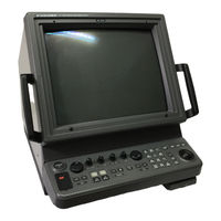
Furuno FR-2155 Operator's Manual (197 pages)
Furuno 21" Multi-Color High-Performance Shipborne Radar and Arpa FR-2105 Series; FR-2105-B Series
Brand:
Furuno
| Category:
Radar
| Size: 5.12 MB
Table of Contents
Table of Contents
7
A Word to the Owner of Furuno Radar
10
Introduction
10
Specifications of Fr-2105/2105-B Series Radar and Arpa
13
Antenna Unit
16
Chapter 1 Operation
18
Turning on the Power
18
Transmitter on
19
Control Head
20
Crt Brilliance
22
Tuning the Receiver
22
On-Screen Legends and Markers
24
Degaussing the Crt Screen
26
Initializing the Gyro Readout
26
Presentation Modes
27
Mode
27
Selecting the Range Scale
30
Selecting the Pulselength
30
Adjusting the Sensitivity
33
Suppressing Sea Clutter
33
Suppressing Precipitation Clutter
35
Interference Rejector
35
Measuring the Range
36
Measuring the Bearing
38
Collision Assessment by Offset Ebl
39
Measuring Range and Bearing between Two Targets
40
Setting a Target Alarm Zone
40
Off-Centering
42
Echo Stretch
43
Echo Averaging
44
Electronic Plotting Aid (Epa)
46
P Lotting a ID (Epa)
46
Entering Own Ship's Speed
50
Target Trails (Echo Trails)
52
Trail (Echo Trail)
52
Parallel Index Lines
55
Index Line
55
Origin Mark
57
Zoom
58
Markers
59
Menu Keys
60
Radar 1, 2 and 3 Menu Settings
61
Function Keys
63
Barge Information
69
Radar Map
69
Suppressing Second-Trace Echoes
74
Displaying External Waypoint and Navigation Line
74
Adjusting Brilliance of Screen Data
75
Display of Wind/Tide/Depth Information
76
Alarms
78
Chapter 2 Operation of Arpa (Option)
80
General
80
Keypads for Arpa
81
Arpa Menu Operation
82
Start-Up Procedure
83
Automatic Acquisition
85
Manual Acquisition
89
Changing Plot Symbol Size
90
Adjusting Brilliance of Plot Marks
93
Displaying Target Data
93
Vector Modes
94
Past Position Display
95
Set and Drift (Set and Rate)
96
Setting Cpa/Tcpa Alarm Ranges
97
Setting a Guard Zone
98
Operational Warnings
100
Trial Maneuver
102
Arpa Performance Test
104
Criteria for Selecting Targets for Tracking
105
Factors Affecting Arpa Functions
107
Chapter 3 Radar Observation
109
General
109
False Echoes
111
SART (Search and Rescue Transponder)
112
RACON (Radar Beacon)
114
Chapter 4 Operation of Video Plotter
115
General
115
The Video Plotter Display
116
Display Modes
116
Chart Position Correction
117
Set- up of Video Plotter Display
118
Track
119
Marks, Lines
122
Waypoints
123
Navigation Lines
126
Recording & Replaying Data
129
Initial Settings
131
Chapter 5 Maintenance
134
Periodic Maintenance Schedule
134
Life Expectancy of Major Parts
135
Replacement of Battery
135
Chapter 6 Troubleshooting
136
Easy Troubleshooting
136
Advanced Level Troubleshooting
137
Diagnostic Test
139
Chapter 7 Menu Overview
142
Chapter 8 Anlillary Equipment
146
Performance Monitor
146
Interswitching Unit
148
For Fishing Vessel
149
Chapter 9 Digital Interface (Iec61162-1)
150
Chapter 10 Parts List and Major Parts Location
161
Advertisement
Furuno FR-2155 Service Manual (152 pages)
Brand:
Furuno
| Category:
Marine Radar
| Size: 14.87 MB
Table of Contents
Table of Contents
6
Chapter1. GENERAL
9
Outline
9
Boards & Major Components
10
Scanner Unit
11
Specifications
12
Display Unit
13
Chapter 2. BLOCK DESCRIPTION
15
Overview
15
Block Diagram of Display Unit
17
Function of each Board (Display Unit)
18
Start-Up Sequence
20
Block Diagram of SPU Board
22
Video Signal Flow
23
Block Diagram of SPU Board (Video Amplifier)
24
Auto Tuning Function
25
Tuning Indication
26
Manual Tuning
26
Tuning Circuit
26
Echo Averaging (EAV 1/2/3)
27
Echo Stretch 1/2 and Enhanced Video
28
Memories & Memory Frame Priority
29
Antenna On/Off Control
30
Check of ARP and RP Board Connection
31
Vs. ARP-26
31
Simple ARPA Block Diagram
32
ARPA Block Diagram
33
ARPA Target Acquisition and Tracking
34
ARPA Land Discrimination
34
Arpa Initial Setting Menu
35
Block Diagram of RP Board
38
INPUT/OUTPUT Data on INT Board (03P9252)
39
Sentences Receivable at J450 on INT-9170
40
Radar and ARPA Output Signal from INT-9170
41
Monitor Signal from J449
42
Power Supply Circuit (AC)
43
Scanner Unit
45
Block Diagram of if AMP Board (03P6734)
46
Block Diagram of if MD Board (03P6666)
47
Block Diagram of PF Board (03P6668/03P6669)
49
BEARING SIG GEN Board (MP-3795)
52
Power Supply Unit (PSU-001)
53
TX-HV Power Supply (03P6680/03P6810)
54
Power Supply (03P6667)
55
Power Supply Unit (PSU-004)
56
Chapter 3. ADJUSTMENT
57
Adjustment (Display Unit)
58
Location of Major Parts
58
Adjustment of CRT
61
Location of Parts on SPU Board (03P9253)
63
Location of Parts on ARP Board (18P9002)
64
Location of Parts on RP Board (14P0298)
65
Location of Parts on INT Board (03P9252)
66
Location of Parts on GYRO Board (64P1106)
67
Location of Parts on Power Supply Unit (PSU-001)
69
Location of Parts on Power Supply Board (03P6667)
70
Location of Parts on INT Board (03P9003)
71
Location of Parts on TX-HV Power Supply Board (1)(03P6810)
72
Location of Parts on TX-HV Power Supply Board (2)(03P6680)
73
Location of Parts on Power Supply Unit (PSU-004)
74
Adjustment (Scanner Unit)
75
Location of Parts on Scanner Unit (RSB-0049/0050)
75
Location of Parts on RF Unit (RTR-030)
76
Location of Parts on Modulator Board (03P6666C)
77
Location of Parts on if AMP Board (03P6734C)
78
Location of Parts on INT Board (03P9004)
79
Location of Parts on PFN (1) Board (03P6668)
80
Location of Parts on PFN (2) Board (03P6669)
81
Chapter 4. MAINTENANCE
82
Dip Switches
83
Jumper Settings
84
LED Status
85
Self-Test
88
Keyboard Test
89
Notice on Replacing Major Parts
90
Program Numbers
91
How to Update System Program
91
Chapter 5. TROUBLESHOOTING
93
Outline
93
Error Message
93
Troubleshooting Flow Charts
93
Schematic Diagrams
120
Furuno FR-2155 Installation Manual (89 pages)
Furuno Marine RADAR User Manual
Brand:
Furuno
| Category:
Marine Radar
| Size: 4.43 MB
Table of Contents
Table of Contents
5
Equipment Lists
6
Optional Equipment
7
System Configuration
8
Mounting
9
Scanner Unit
9
Display Unit
14
Power Supply Units
22
Wiring
23
Scanner Unit
23
Display Unit
27
Changing AC Power Specification of Display Unit
32
Power Supply Units
33
Initialization and Adjustment
35
Tuning Initialization
35
Accessing Menus for Initialization and Adjustment
35
Adjusting Video Signal Level
35
Heading Alignment
36
Adjusting Sweep Timing
37
Suppressing Main Bang
37
Confirming Magnetron Heater Voltage
38
Initial Setting Menus
40
Installation of Optional Equipment
43
Gyro Converter GC-8
43
ARP Board ARP-26
49
RP Board RP-26
52
Performance Monitor PM-30
56
Alarm Kit
57
Advertisement
Advertisement
Related Products
Furuno FR-2150W Operators
Furuno FR-2150 Operators
Furuno FR-2115/2125
Furuno FR-2135S
Furuno FR-2115-B
Furuno FR-2110 Operators
Furuno FR-2130SW Operators
Furuno FR-2160DS Operators
Furuno FR-2120 Operators
Furuno FR-2120W Operators
Furuno Categories
Marine Radar
Marine Equipment
Sonar
Monitor
GPS
More Furuno Manuals
Login
Sign In
OR
Sign in with Facebook
Sign in with Google
Upload manual
Upload from disk
Upload from URL