Fujitsu ABHG18KRTA Manuals
Manuals and User Guides for Fujitsu ABHG18KRTA. We have 5 Fujitsu ABHG18KRTA manuals available for free PDF download: Design & Technical Manual, Service Manual

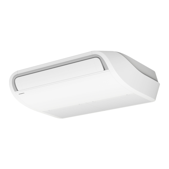
Fujitsu ABHG18KRTA Design & Technical Manual (572 pages)
3-unit multi-split type, INDOOR/OUTDOOR
Brand: Fujitsu
|
Category: Air Conditioner
|
Size: 32 MB
Table of Contents
-
Model Lineup10
-
Ceiling Type42
-
Floor Type43
-
Dimensions45
-
Rear View53
-
Front View53
-
Ceiling Type75
-
Floor Type77
-
Ceiling Type96
-
Floor Type97
-
Mini Duct Type105
-
Slim Duct Type115
-
Ceiling Type132
-
Floor Type133
-
Fan Performance134
-
Mini Duct Type134
-
Slim Duct Type144
-
Mini Duct Type161
-
Slim Duct Type162
-
Ceiling Type175
-
Floor Type176
-
Mini Duct Type180
-
Slim Duct Type183
-
Ceiling Type196
-
Floor Type197
-
Safety Devices205
-
Indoor Unit210
-
External Output212
-
Function Setting215
-
Rotary Switch217
-
Input Signal217
-
Error Status218
-
Indoor Unit242
-
Input Select243
-
Output Signal252
-
12-6.Floor Type254
-
Operation262
-
Group Connection263
-
Display Panel266
-
System Diagram284
-
Installation285
-
System Diagrams289
-
Group Control291
-
On/Off Button297
-
Display Panel297
-
System Diagram298
-
Terminal Screw306
-
Mode Button317
-
Filter Sign372
-
Factory Setting375
-
Auto Restart376
-
Switch Location379
-
Accessories384
-
16-7.Floor Type399
-
Optional Parts400
-
17-1.Controllers400
-
17-3.Others408
-
Specifications424
-
Dimensions426
-
Wiring Diagram431
-
Capacity Table432
-
Combinations432
-
Cooling Capacity439
-
Mini Duct Type443
-
Slim Duct Type444
-
Floor Type462
-
Mini Duct Type469
-
Slim Duct Type471
-
Ceiling Type491
-
Floor Type492
-
Heating Capacity493
-
Mini Duct Type497
-
Slim Duct Type498
-
Floor Type516
-
Airflow550
-
Safety Devices554
-
Setting Method556
-
Check and Test559
-
14-2.Test Run565
-
14-3.Error Code566
-
Error Type568
-
Accessories571
Advertisement

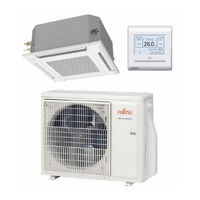
Fujitsu ABHG18KRTA Service Manual (441 pages)
3-unit multi-split type
Brand: Fujitsu
|
Category: Air Conditioner
|
Size: 34 MB
Table of Contents
-
Ceiling Type22
-
Floor Type23
-
Outdoor Unit24
-
Dimensions26
-
Ceiling Type48
-
Floor Type50
-
Outdoor Unit52
-
Service Part59
-
Control Box83
-
Ceiling Type128
-
Floor Type130
-
Drain Pan134
-
Mini Duct Type141
-
Slim Duct Type143
-
Ceiling Type150
-
Floor Type151
-
Outdoor Unit152
-
Ceiling Type165
-
Floor Type166
-
Outdoor Unit167
-
Troubleshooting183
-
Error Code187
-
Error Message195
-
Abnormal Noise255
-
Water Leaking256
-
Button Mode265
-
Compressor269
-
Indoor Unit280
-
Outdoor Unit281
-
Mini Duct Type293
-
Slim Duct Type294
-
Ceiling Type298
-
Floor Type299
-
Dry Operation301
-
Fan Control312
-
Fan Operation312
-
Ceiling Type335
-
Fan Speed335
-
Floor Type338
-
Louver Control344
-
Swing Operation348
-
On/Off Timer349
-
Program Timer349
-
Sleep Timer350
-
Weekly Timer352
-
Various Control358
-
Auto Restart358
-
C HEAT Operation359
-
Overflow Control363
-
Operation Mode366
-
Wall Mounted366
-
Operation371
-
Function Details412
-
Filter Sign414
-
Factory Setting417
-
Auto Restart418
-
Switch Location421
-
Setting Methods426
-
Setting Method427
-
Check and Test430
-
Test Run436
-
Indoor Unit436
-
Error Code437
-
Error Type439
-
Pump down440
Fujitsu ABHG18KRTA Service Manual (471 pages)
Brand: Fujitsu
|
Category: Air Conditioner
|
Size: 38 MB
Table of Contents
-
-
Abnormal Noise285
-
Water Leaking286
-
Compressor299
-
Indoor Unit310
-
Outdoor Unit311
-
-
Dry Operation330
-
Fan Control340
-
Louver Control375
-
Swing Operation379
-
Auto Restart389
-
Various Control389
-
C HEAT Operation390
-
5. Filed Working
404-
Function Details442
-
Setting Methods456
-
Check and Test460
-
Check Run460
-
Test Run466
-
Error Code467
-
Pump down470
Advertisement
Fujitsu ABHG18KRTA Design & Technical Manual (113 pages)
Brand: Fujitsu
|
Category: Air Conditioner
|
Size: 9 MB
Table of Contents
-
Dimensions14
-
Airflow30
-
Accessories61
-
12-2.Others64
-
Dimensions70
-
Airflow95
-
Safety Devices102
-
Accessories111
-
Optional Parts113

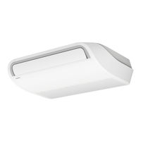
Fujitsu ABHG18KRTA Design & Technical Manual (113 pages)
Ceiling type Air Conditioner
Brand: Fujitsu
|
Category: Air Conditioner
|
Size: 6 MB
Table of Contents
-
Dimensions14
-
Airflow30
-
Accessories61
-
12-2.Others64
-
Dimensions71
-
Airflow95
-
Safety Devices102
-
Accessories112
-
Optional Parts113
Advertisement