Sign In
Upload
Manuals
Brands
Fuji Electric Manuals
Servo Drives
FRENIC-ECO
User Manuals: Fuji Electric FRENIC-ECO Frequency Drive
Manuals and User Guides for Fuji Electric FRENIC-ECO Frequency Drive. We have
1
Fuji Electric FRENIC-ECO Frequency Drive manual available for free PDF download: Instruction Manual
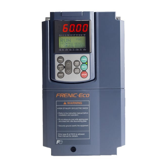
Fuji Electric FRENIC-ECO Instruction Manual (247 pages)
Designed for Fan and Pump Applications
Brand:
Fuji Electric
| Category:
Servo Drives
| Size: 5 MB
Table of Contents
Preface
3
Safety Precautions
3
Application
4
Installation
4
Wiring
5
Operation
6
Disposal
7
Maintenance and Inspection, and Parts Replacement
7
Others
7
Setting Control Switches
7
Conformity with Low Voltage Directive in the EU
8
Conformity with UL Standards and CSA Standards (Cul-Listed for Canada)
10
Precautions for Use
12
How this Manual Is Organized
15
Icons
15
Table of Contents
16
Acceptance Inspection
17
Nameplates
17
Chapter 1 BEFORE USING the INVERTER
17
External View and Terminal Blocks
18
Outside and Inside Views of Inverters
18
Warning Plates and Label
19
Terminal Blocks and Keypad Enclosure Location
19
Transportation
20
Storage Environment
20
Temporary Storage
20
Long-Term Storage
20
The Inverter
20
Operating Environment
21
Installing the Inverter
21
Mounting Base
21
Chapter 2 MOUNTING and WIRING of the INVERTER
21
When Employing External Cooling
22
When Mounting Two or more Inverters
22
Screw Count and Tightening Torque
23
Relocating the Top and Bottom Mounting Bases
24
Fixing Screws
25
Fixing the Cooling Fan(S)
25
Mounting Direction
25
Solving Abnormal Vibration after Installation
25
Fixing the Keypad (for Models of 30HP for 208V, 40HP for 460V or Below)
26
For Inverters with a Capacity of 30HP for 208V, 40HP for 460V or below
26
Removing and Mounting the Terminal Block (TB) Cover and the Front Cover
26
Removing the Covers (FRN015F1S-2U)
26
Wiring
26
Mounting the Covers (FRN015F1S-2U)
27
For Inverters with a Capacity of 40HP for 208V, 50HP for 460V to 125HP for 208V, 200HP for 460V
28
Removing and Mounting the Covers
28
Removing the Front Cover (FRN040F1S-2U)
28
For Inverters with a Capacity of 250HP to 300HP
29
Removing the Front Covers (FRN350F1S-4U)
29
Opening Half-Punched Holes and Mounting Rubber Bushes
30
Removing and Mounting the Cable Guide Plate (for Models of 1 to 25HP for 208V and 1 to 30HP for 460V)
30
Removing the Cable Guide Plate (FRN015F1S-2U)
30
Main Circuit Terminal Properties
31
Terminal Arrangement Diagram and Screw Specifications
31
Control Circuit Terminals
33
The Control Circuit Terminals (Common to All Models
33
The RS-485 Communication Terminals
33
Recommended Wire Sizes
34
Wiring for Main Circuit Terminals and Grounding Terminals
35
Wiring Precautions
35
Wiring Procedure for Peripheral Equipment
36
Drive Output Terminals (U, V, W)
37
Grounding Terminals
37
Main Circuit Power Terminals (L1/R, L2/S, L3/T)
37
DC Reactor Terminals, P1 and P (+)
38
Power Switching Connectors (CN UX) (for the Models of 460 V 75HP or Above)
38
Fan Power Supply Switching Connectors (CN R) and (CN W) (for Models of 50HP or above (208 V) or 75HP or above (460 V))
39
Switching Fan Power Source
39
Inserting/Removing the Jumpers
40
Location of Switching Connectors and Auxiliary Power Input Terminals
40
Setting up the Jumpers for the Connectors (CN UX), (CN R) and (CN W)
40
Reconfiguration of the (CN UX), (CN R) and (CN W) Connectors
41
Setting up the Fan Power Supply Switching Connectors (CN R) and (CN W)(for the Models of 208 V 50HP or Above; 460 V 75HP or Above)
41
Setting up the Power Switching Connector (CN UX)(for the Models of 460 V 75HP or Above)
41
Auxiliary Power Input Terminals R0 and T0 for the Control Circuit
42
Connection Example of Residual-Current-Operated Protective Device (Rcd)/Ground Fault Circuit Interrupter (GFCI)
42
DC Link Bus Terminals, P (+) and N (-)
42
Main Circuit Power Input Terminals, L1/R, L2/S, and L3/T (Three-Phase Input)
42
9 Auxiliary Power Input Terminals R1 and T1 for the Fan
43
Connection Example of PWM Converter
43
Wiring for Control Circuit Terminals
44
Symbols, Names and Functions of the Control Circuit Terminals
45
Connection of Shielded Wire
46
Example of Electric Noise Reduction
46
Digital Input Circuit
47
Circuit Configuration Using a PLC
48
Circuit Configuration Using a Relay Contact
48
Using a Programmable Logic Controller (PLC) to Turn [X1], [X2], [X3], [X4], [X5], [FWD], or [REV] on or off
48
Using a Relay Contact to Turn [X1], [X2], [X3], [X4], [X5], [FWD], or [REV] on or off
48
Connecting PLC to Control Circuit
50
Connecting Programmable Controller (PLC) to Terminal [Y1], [Y2] or [Y3]
50
Transistor Output Circuit
50
RJ-45 Connector and Its Pin Assignment
51
RS-485 Communications Card
52
For Models of FRN200F1S-4U to FRN350F1S-4U
53
Routing and Fastening the Control Circuit Cable
53
Setting up Slide Switches and Handling Control Circuit Terminal Symbol Plate
54
Location of the Slide Switches
55
Mounting and Connecting a Keypad
55
Mounting Style and Parts Needed for Connection
55
Parts Needed for Connection
56
Mounting/Installing Steps
56
Mounting a Keypad on the Enclosure Wall
56
Using the Multi-Function Keypad in Hand
57
Retracting the Keypad into the Inverter
57
Cautions Relating to Harmonic Component, Noise, and Leakage Current
58
Harmonic Component
58
Leakage Current Countermeasures
58
Key, LED, and LCD Monitors on the Keypad
59
Chapter 3 OPERATION USING the MULTI-FUNCTION KEYPAD
59
Overview of Keypad Functions
60
Items Displayed on LED Indicators
61
Overview of Operation Modes
62
Running Mode
63
Running/Stopping the Motor
63
Display of Running Status (on LCD Monitor)
63
(2) When Function Code E45 (LCD Monitor (Optional)) Is Set to "1," the LCD Monitor Displays the Output
64
Switching the Operation Mode between Remote and Local
64
Run Commands from the Keypad in the Local Operation Mode
65
Transition between Remote and Local Modes
65
Setting up the Frequency and PID Process Commands
66
Available Means of Setting
67
Make Setting under PID Control
68
PID Process Commands
68
LED Monitor (Monitoring the Running Status)
70
Selecting Items to be Monitored on LED Monitor
70
Menus Available in Programming Mode
71
Function Codes Available on Frenic-Eco
72
Function Codes Requiring Simultaneous Keying
72
Modifying Function Code Data During Running; Making the Modification Valid and Saving the Modification
72
Setting Function Codes - "1. Data Setting
72
Basic Key Operation
73
Screen for Changing Function Code Data
73
Additional Note on Function Code Being Selected
73
Changing Function Code Data
74
Checking Changed Function Codes –"2. Data Check"
75
LCD Screen Listing Function Codes
75
Setting up Function Codes Quickly Using Quick Setup - "0. QUICK SET
75
Drive Monitoring Display Items
76
Monitoring the Running Status -"3. OPR MNTR
76
Menu Transition for "OPR MNTR"
77
Checking I/O Signal Status – "4. I/O Check"
78
I/O Check Items
78
Menu Transition for "I/O Check"
79
Hexadecimal Expression
80
Displaying Control I/O Signal Terminals under Communication Control
80
Display Items for Maintenance
81
Reading Maintenance Information - "5. MAINTENANC
81
Menu Transition for "Maintenanc"
83
Alarm Information Displayed
84
Reading Alarm Information - "6. ALM INF
84
Menu Transition for "ALM INF"
85
Viewing Cause of Alarm - "7. ALM CAUSE
87
Menu Transition for "ALM Cause"
88
Selecting Copy Operation
89
List of Data Copy Operations
89
Data Copying - "8. DATA COPY
89
Read Operation
90
Error Screens
90
Write Operation
91
Verify Operation
93
Check Operation
95
Error Screen for "Data Copy"
95
Menu Transition for Selecting Measurement Mode
96
Measuring Load Factor - "9. LOAD FCTR
96
Selecting "Hours Set" Mode
97
Selecting "Start to Stop" Mode
98
Going Back to Running Mode
98
Changing Function Codes Covered by Quick Setup - "10. USER SET
99
Performing Communication Debugging - "11. COMM DEBUG
100
Alarm Mode
101
If There Is an Overlapping Alarm
101
If There Is no Overlapping Alarm
101
Switching of Display of Overlapping Alarm History
101
Display of Running Status Information at the Time of Alarm
102
Resetting Alarm; Transition to Running Mode
102
Transition to Programming Mode
102
Other Precautions
103
Function Code Setting for F02 (Run and Operation)
103
Remote/Local Operation
103
Tuning Motor Parameters
104
Running the Motor for a Test
105
Inspection and Preparation Prior to Powering on
105
Turning on Power and Checking
105
Preparation before Running the Motor for a Test--Setting Function Code Data
105
Chapter 4 RUNNING the MOTOR
105
Selection of Tuning Process
106
Settings of Function Code Data before Driving the Motor for a Test
106
Errors During Tuning
107
Perform Tuning
107
Preparation of Machine System
107
Operation
108
Test Run
108
Changing, Validating, and Saving Function Code Data When the Inverter Is Running
109
Copying Data
109
Function Code Tables
109
Chapter 5 FUNCTION CODES
109
Using Negative Logic for Programmable I/O Terminals
110
F Codes: Fundamental Functions
111
E Codes: Extension Terminal Functions
115
C Codes: Control Functions of Frequency
120
P Codes: Motor Parameters
121
H Codes: High Performance Functions
122
J Codes: Application Functions
125
Y Codes: Link Functions
128
208V Default Setting
130
460V Default Setting
130
Data Protection
131
Frequency Command 1, 2
131
Overview of Function Codes
131
Run Command
132
Maximum Frequency
133
Base Frequency
134
Non-Linear V/F Pattern (Frequency)
134
Non-Linear V/F Pattern (Voltage)
134
Rated Voltage at Base Frequency
134
Normal (Linear) V/F Pattern
135
V/F Pattern with Non-Linear Point above the Base Frequency
135
V/F Pattern with Non-Linear Point below the Base Frequency
135
Acceleration Time 1
136
Deceleration Time 1
136
Load Selection/Auto Torque Boost/Auto Energy Saving Operation
136
Torque Boost
136
Manual Torque Boost (F09)
137
V/F Characteristics
137
Auto Energy Saving Operation
138
Automatic Torque Boost
138
Electronic Thermal Overload Protection for Motor (Select Motor Characteristics, Overload Detection Level, and Thermal Time Constant)
139
Select Motor Characteristics (F10)
139
Overload Detection Level (F11)
140
Thermal Time Constant (F12)
140
Example of Operating Characteristics
141
Restart after Momentary Power Failure
142
Restart Mode after Momentary Power Failure (Mode Selection)
142
Restart Mode after Momentary Power Failure (Mode Selection) (F14)
142
Restart Mode after Momentary Power Failure (Basic Operation)
143
Restart Mode after Momentary Power Failure (Allowable Momentary Power Failure Time) (H16)
145
Auto-Restart after a Recovery from Momentary Power Failure (Waiting Time) (H13)
146
Factory Default
146
Frequency Limiter (High)
147
Frequency Limiter (Low)
147
Restart after Momentary Power Failure (Frequency Fall Rate) (H14)
147
Analog Input Adjustment for [12] (Gain, Gain Reference Point)
148
Analog Input Adjustment for [C1] (Gain, Gain Reference Point)
148
Analog Input Adjustment for [V2] (Gain, Gain Reference Point)
148
Bias, Bias Reference Point (Frequency Command 1)
148
DC Braking (Braking Response Mode)
149
DC Braking (Braking Start Frequency, Braking Level, and Braking Time)
149
Motor Sound (Carrier Frequency)
150
Motor Sound (Tone)
150
Starting Frequency
150
Stop Frequency
150
Analog Output [FMA]
151
Mode Selection (F29)
151
Motor Sound (Tone) (F27)
151
Function (F31)
152
Output Adjustment (F30)
152
Command Assignment to [FWD] and [REV]
153
Command Assignment to [X1] to [X5]
153
Terminal [FMI]
153
Coast to a Stop-(BX) (Function Code Data = 7)
155
Enable 3-Wire Operation-(HLD) (Function Code Data = 6)
155
Select Multistep Frequency (1 to 7 Steps)–(SS1), (SS2), and (SS4) (Function Code Data = 0, 1, and 2)
155
Enable DC Brake-(DCBRK) (Function Code Data = 13)
156
Enable External Alarm Trip-(THR) (Function Code Data = 9)
156
Reset Alarm-(RST) (Function Code Data = 8)
156
Switch Frequency Command 2/1-(Hz2/Hz1) (Function Code Data = 11)
156
Enable Write from Keypad-(WE-KP) (Function Code Data = 19)
157
Switch Normal/Inverse Operation-(IVS) (Function Code Data = 21)
157
Enable Communications Link Via RS-485 or Field Bus (Option)-(LE) (Function Code Data = 24)
158
Interlock-(IL) (Function Code Data = 22)
158
Force to Stop-(Stop) (Function Code Data = 30)
159
Select Starting Characteristics-(STM) (Function Code Data = 26)
159
Switch Run Command 2/1-(FR2/FR1), Run Forward 2 and Run Reverse 2-(FWD2) and (REV2) (Function Code Data = 87, 88 or 89)
159
Universal DI-(U-DI) (Function Code Data = 25)
159
Run Forward-(FWD) (Function Code Data = 98)
160
Run Reverse-(Rev) (Function Code Data = 99)
160
Signal Assignment to [Y1] to [Y3] (Transistor Signal)
160
Signal Assignment to [Y5A/C] and [30A/B/C] (Relay Contact Signal)
160
Auto-Restarting after Momentary Power Failure-(IPF) (Function Code Data = 6)
163
Inverter Output Limiting-(IOL) (Function Code Data = 5)
163
Inverter Running-(Run) (Function Code Data = 0)
163
Undervoltage Detected-(LU) (Function Code Data = 3)
163
Inverter Ready to Run-(RDY) (Function Code Data = 10)
164
Motor Overload Early Warning-(OL) (Function Code Data = 7)
164
Select AX Terminal Function-(AX) (Function Code Data = 15)
164
Cooling Fan in Operation-(Fan) (Function Code Data = 25)
165
Heat Sink Overheat Early Warning-(OH) (Function Code Data = 28)
165
Service Life Alarm-(Life) (Function Code Data = 30)
165
Universal DO-(U-DO) (Function Code Data = 27)
165
Current Detected-(ID) (Function Code Data = 37)
166
Low Output Torque Detected-(U-TL) (Function Code Data = 45)
166
Overload Prevention Control-(OLP) (Function Code Data = 36)
166
Terminal C1 off Signal-(C1OFF)
166
Frequency Detection (FDT) (Detection Level)
167
Frequency Detection (FDT) (Hysteresis Width)
167
Overload Early Warning/Current Detection (Level)
167
Overload Early Warning/Current Detection (Timer)
167
Command Loss Detection (Level)
168
Display Coefficient for Input Watt-Hour Data
168
Detect Low Torque (Detection Level)
169
Detect Low Torque (Timer)
169
Motor (No. of Poles)
169
Motor (Rated Capacity)
169
Motor (%R1)
170
Motor (Auto-Tuning)
170
Motor (No-Load Current)
170
Motor (Rated Current)
170
Data Initialization
171
Motor Selection
171
Auto-Resetting (Reset Interval)
172
Auto-Resetting (Times)
172
Number of Resetting Times (H04)
172
Reset Interval (H05)
172
Acceleration/Deceleration Pattern
173
Acceleration/Deceleration Time
173
Cooling Fan On/Off Control
173
S-Curve Acceleration/Deceleration
173
Curvilinear Acceleration/Deceleration
174
Searching for Idling Motor Speed
174
Select Starting Characteristics (Auto Search for Idling Motor Speed)
174
Select Starting Characteristics (Frequency for Idling Motor Speed)
174
Auto Search for Idling Motor Speed (H09)
175
Frequency for Idling Motor Speed (H17)
175
Select Starting Characteristic (STM) (Digital Input Signal)
175
Deceleration Mode
176
Starting Patterns
176
Bus Link Function (Function Selection)
177
Command Sources Selectable
177
Communications Link Function (Mode Selection)
177
Instantaneous Overcurrent Limiting
177
Combination of Command Source
178
Command Sources Specified by H30
178
Command Sources Specified by Y98
178
Automatic Deceleration
179
Overload Prevention Control
179
PID Control Feedback Line Disconnection Detection Protection
179
Automatic Lowering Function of Carrier Frequency
180
Clear Alarm Data
180
Cumulative Run Time of Motor
180
Protection/Maintenance Function
180
Detection of DC Fan Lock (208 V: 50HP or Above, 460 V: 75HP or Above)
181
Judgment on the Life of DC Link Bus Capacitors
181
Conversion Table (Decimal To/From Binary)
183
Dew Condensation Prevention (Duty)
184
Dew Condensation Prevention (Duty) (J21)
184
Enabling Dew Condensation Prevention
184
Before Proceeding with Troubleshooting
185
Chapter 6 TROUBLESHOOTING
185
If no Alarm Code Appears on the LED Monitor
186
Motor Is Running Abnormally
186
The Motor Does Not Rotate
186
The Motor Rotates, but the Speed Does Not Increase
187
The Motor Runs in the Opposite Direction to the Command
188
If the Speed Variation and Current Vibration (such as Hunting) Occur at the Constant Speed
188
If Grating Sound Can be Heard from Motor
189
The Motor Does Not Accelerate and Decelerate at the Set Time
190
Even if the Power Recovers after a Momentary Power Failure, the Motor Does Not Restart
190
Problems with Inverter Settings
191
Nothing Appears on the LED Monitor
191
The Desired Menu Is Not Displayed
191
Data of Function Codes Cannot be Changed
191
If an Alarm Code Appears on the LED Monitor
192
Quick Reference Table of Alarm Codes
192
Ocn Instantaneous Overcurrent
192
EF Ground Fault (125 HP or Above)
193
Oun Overvoltage
193
LU Undervoltage
194
L Input Phase Loss
194
OPL Output Phase Loss
195
OH1 Heat Sink Overheat
195
OH2 Alarm Issued by an External Device
196
OH3 Inside of the Inverter Overheat
196
OH4 Motor Protection (PTC Thermistor)
196
FUS Fuse Blown (125HP or Above)
197
Pbf Charger Circuit Fault (50HP or above (208 V), 75HP or above (460 V))
197
OL1 Electronic Thermal Overload Relay
198
OLU Overload
198
Er1 Memory Error
199
Er2 Keypad Communications Error
199
Er3 CPU Error
199
Er4 Option Card Communications Error
200
Er5 Option Card Error
200
Er6 Incorrect Operation Error
200
Er7 Tuning Error
201
Er8 RS-485 Communications Error
201
Erf Data Saving Error During Undervoltage
202
Erp RS-485 Communications Error
202
Erh LSI Error (Power PCB) (50HP or above (208 V); 75HP or above (460 V))
203
If an Abnormal Pattern Appears on the LED Monitor While no Alarm Code Is Displayed
203
Daily Inspection
205
Periodic Inspection
205
Chapter 7 MAINTENANCE and INSPECTION
205
List of Periodical Replacement Parts
207
Judgment on Service Life
207
Viewing Data Necessary for Judging Service Life; Measurement Procedures
207
Procedure for Measuring Capacitance
207
Procedure for Setting up Measurement Condition
208
Early Warning of Lifetime Alarm
209
Criteria for Issuing a Lifetime Alarm
209
Measurement of Electrical Amounts in Main Circuit
209
Meters for Measurement of Main Circuit
209
Connection of Meters
210
Insulation Test
210
Megger Test of Main Circuit
210
Dielectric Strength Test of External Main Circuit and Sequence Control Circuit
210
Inquiries about Product and Guarantee
211
Standard Models
212
Three-Phase 208V
212
Chapter 8 SPECIFICATIONS
212
Three-Phase 460 V
213
1 To 75HP
213
100 To 900HP
214
Specifications of Keypad Related
215
General Specifications of Keypad
215
Communications Specifications of Keypad
215
Data Transmission Specifications
216
Common Specifications
217
Terminal Specifications
219
Terminal Functions
219
Running the Inverter with Keypad
220
Running the Inverter by Terminal Commands
221
External Dimensions
223
Standard Models
223
DC Reactor
226
Multi-Function Keypad
227
Protective Functions
228
Options
229
Chapter 9 LIST of PERIPHERAL EQUIPMENT and OPTIONS
231
Conformity with UL Standards and Canadian Standards (Cul-Listed for Canada)
235
Conformity with EU Directives
235
Conformity with Low Voltage Directive
235
Chapter 10 CONFORMITY with STANDARDS
235
General
235
Considerations When Using FRENIC-Eco as a Product Certified by UL or Cul
235
Considerations When Using FRENIC-Eco as a Product in Conformity with Low Voltage Directive
235
Harmonic Component Regulation in the EU
236
Conformity with the Harmonics Regulation
236
Connection to Power Line
236
General
236
Conformity with the EMC Directive in the EU
237
EMC-Compliant Filter (Option)
237
General
237
EMC-Compliant Filters and Leakage Current
238
Recommended Installation of EMC-Compliant Filter
239
EMC-Compliant Filter and Panel-Mount Adapter (Option)
239
Installing Inverter and EMC-Compliant Filter
239
Basic Connection Procedure
240
Installation of EMC-Compliant Filter (Option)
240
EMC-Compliant Environment and Class
240
Internal Location Diagram (FRN150F1S-4U)
241
Internal Location Diagram (FRN200F1S-4U)
242
Internal Location Diagram (FRN250F1S-4U to FRN350F1S-4U)
243
Advertisement
Advertisement
Related Products
Fuji Electric FRN005F1S-2DY
Fuji Electric FRENIC-Eco Series
Fuji Electric Frenic Eco Series
Fuji Electric FRENIC-EcoPAK
Fuji Electric FRENIC-eHVAC
Fuji Electric FRENIC-Multi
Fuji Electric FRENIC-Lift series
Fuji Electric FRENIC-Multi Series
Fuji Electric frenic-hvac
Fuji Electric Frenic-Sce
Fuji Electric Categories
Air Conditioner
Inverter
Measuring Instruments
Controller
Control Unit
More Fuji Electric Manuals
Login
Sign In
OR
Sign in with Facebook
Sign in with Google
Upload manual
Upload from disk
Upload from URL