Sign In
Upload
Manuals
Brands
Fluke Manuals
Multimeter
8842A
Fluke 8842A Manuals
Manuals and User Guides for Fluke 8842A. We have
2
Fluke 8842A manuals available for free PDF download: Instruction Manual
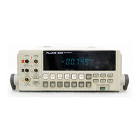
Fluke 8842A Instruction Manual (269 pages)
Brand:
Fluke
| Category:
Multimeter
| Size: 13.88 MB
Table of Contents
Instruction Manual
1
Table of Contents
3
Title Page
15
Introduction and Specifications
15
Introduction
16
The 8842A Digital Multimeter
16
Options and Accessories
16
Specifications
17
External Dimensions
17
Introduction
25
Adjusting the Handle
26
Connecting to Line Power
27
Installation
27
Installing the Power-Line Fuse
27
Introduction
27
Adjusting the Handle
28
Installation
26
Introduction
26
Operating Instructions
26
Rack-Mount Kits
28
Rack Mounting Kits
28
Operating Features
29
Power-Up Features
29
Front and Rear Panel Features
29
Installing the Single Rack Mount Kit
29
Front Panel Features
30
Rear Panel Features
32
Typical Error Messages
33
Display Features
33
Error Messages
33
Error Codes
34
Overrange Indication
35
Diagnostic Self-Tests
35
Ranging
35
Autorange
35
Manual Range
36
Triggering
36
Continuous Trigger Mode
36
External Trigger Mode
36
Reading Rates and Noise Rejection
36
Overrange Indication
37
Automatic Settling Time Delay
37
External Trigger Input (Option -05 Only)
37
Sample Complete Output (Option -05 Only)
37
Making Measurements
38
Input Overload Protection Limits
38
Measuring Voltage and Resistance
38
Measuring Current
38
Current Fuse Protection
38
Offset Measurements
39
External Cleaning
40
Measuring Voltage and Resistance
40
Measuring Current
40
Remote Programming
42
Introduction
44
Capabilities
44
Bus Set-Up Procedure
44
An Overview of Remote Operation
45
IEEE-488 Address Selection
45
Remote Operation Block Diagram
46
A Note about Examples
47
Device-Dependent Command Set
47
Typical Command String
47
Commands Which Correspond to the Front Panel
48
Device-Dependent Command Set
49
Chapter 3
50
Bn (Offset Commands)
50
Cn (Calibration Commands)
50
Dn (Display Commands)
50
Fn (Function Commands)
51
Output Data Format
51
Get Commands
51
Status Data
52
G0 (Get Instrument Configuration)
53
G1 (Get SRQ Mask)
53
G2 (Get Calibration Prompt)
53
G3 (Get User-Defined Message)
54
G4 (Get Calibration Status)
54
G5 (Get IAB Status)
55
G6 (Get YW Status)
55
G7 (Get Error Status)
55
G8 (Get Instrument Identification)
56
N (Numeric Entry Command)
56
Put Commands
56
P0 (Put Instrument Configuration)
56
P1 (Put SRQ Mask)
57
P2 (Put Calibration Value)
57
P3 (Put User-Defined Message)
58
Rn (Range Commands)
58
Sn (Reading Rate Commands)
58
Trigger Selection Logic Diagram
59
Tn (Trigger Mode Commands)
59
Wn (Terminator Commands)
60
X0 (Clear Error Register Command)
60
Yn (Suffix Commands)
60
Z0 (Self-Test Command)
60
Device-Clear Command)
61
(Single-Trigger Command)
61
Input Syntax
61
Definitions
62
Input Processing
62
Interpretation of Messages
63
Syntax Rules
64
Output Data
65
Loading Output Data
65
Types of Output Data
66
Numeric Data and Error Messages
66
Measurement Data
66
Numeric Output Data Format
66
Overrange Indication
67
Error Messages
67
Status Data
67
Output Priority
67
Service Requests
68
The Serial Poll Register
68
The SRQ Mask
69
Serial Poll Register
69
Interface Messages
70
Address Messages
70
Universal Commands
70
Addressed Commands
71
Talk-Only Mode
71
Remote Calibration
72
Timing Considerations
72
Immediate Mode Commands
72
Example Programs
73
Immediate-Mode Commands for Various Controllers
73
Example Programs
74
Example Program: Taking Readings with Local Control
75
Example Program: Using the Serial Poll Register
76
Example Program: Record Errors During Selftest
77
Example Programs: Using the IBM PC
78
ASCII/IEEE Std 488-1978 Bus Codes
90
Measurement Tutorial
92
Chapter 4
93
Introduction
93
DC Voltage Measurement
93
Circuit Loading Error
93
Circuit Loading Error Calculation
93
Input Bias Current Error
94
Measuring Input Bias Current Error
94
Resistance Measurement
95
2-Wire Ohms
95
Wire Ohms Measurement
95
Correcting for Test Lead Resistance in 2-Wire Ohms
96
4-Wire Ohms
96
Ohms Test Current
97
Wire Ohms Measurement
97
Applications of the Ohms Functions
98
Testing Diodes
98
Testing Electrolytic Capacitors
98
A Precision Current Source
99
DC Current Measurement
99
Reducing Thermal Voltages
100
Burden Voltage Error Calculation
100
Ac Voltage and Current Measurement
101
True RMS Measurement
101
Waveform Comparison
101
Waveform Comparison Chart
102
Crest Factor
103
AC-Coupled AC Measurements
103
Combined AC and DC Measurements
104
Bandwidth
104
Zero-Input VAC Error
104
MAKING ACCURATE MEASUREMENTS on the 20 MV and 20 RANGES
105
Reduction of Zero-Input Error
105
MAKING ACCURATE MEASUREMENTS on the 20 MV
105
Making Accurate High-Resistance Measurements
106
Shielding for Low Voltage Measurements
106
Shielding for Low Resistance Measurements
106
Leakage Resistance in High Resistance Measurement
107
Theory of Operation
108
Chapter 5
110
Introduction
110
Overall Functional Description
110
Detailed Circuit Description
111
DC Scaling
111
Overall Functional Block Diagram
112
VDC Scaling
113
VDC Protection
114
Ma DC Scaling
114
Analog Filter
114
Track/Hold Circuit
115
Track/Hold Amplifier
115
Track/Hold Circuit Configurations
116
Track Configuration
117
Timing Diagram for One A/D Cycle
117
Settling Configuration
118
Hold Configuration
118
Pre-Charge Configuration
118
Precision Voltage Reference
118
Ohms Current Source
119
Ohms Protection
120
Ohms Functions
120
2-Wire Ohms
120
Ohms Scaling
121
4-Wire Ohms
122
A/D Converter
122
Analog-To-Digital Converter
123
Timing/Data Control
124
Precision DAC
124
First Remainder-Store Period
124
A/D Amplifier
125
Bootstrap Supplies
125
Display
125
Autozero Period
125
Keyboard
126
Digital Controller
126
Vacuum Fluorescent Display
126
Digital Controller Block Diagram
127
In-Guard Microcomputer
128
Read/Write Timing Diagrams for Internal Bus
129
Function and Range Control
130
A/D Control and Computation
130
Calibration Correction
130
Sample Rates and Reading Rates
130
Keyboard/Display Control
131
Troubleshooting Modes
131
Guard-Crossing Communication
131
Guard Crossing
131
Guard Crossing Circuit
131
Power Supply
132
Ieee-488 Interface (Option -05)
133
Out-Guard Microcomputer
133
Guard Crossing
133
IEEE-488 Interface Block Diagram
133
Bus Interface Circuitry
133
Signal Conditioning
134
IEEE-488 Interface Power Supply
134
True Rms Ac (Option -09)
134
True RMS AC Option Block Diagram
134
VAC Scaling
134
Ma AC Scaling
135
Frequency Response Trimming
135
True RMS AC-To-DC Conversion
135
True RMS AC-To-DC Converter
135
Maintenance
138
Chapter 6
140
Introduction
140
Recommended Test Equipment
140
Performance Test
141
Diagnostic Self-Tests
141
DC Voltage Test
142
DC Calibration Connections
143
DC Voltage Test
143
AC Voltage Test (Option -09 Only)
144
Low- and MID-Frequency AC Voltage Test
144
Resistance Test
145
High-Frequency AC Voltage Test
145
DC Current Test
146
Resistance Test
146
AC Current Test (Option -09 Only)
147
Calibration
147
Basic Calibration Procedure
148
Initial Procedure
148
First A/D Calibration Prompt
148
A/D Calibration
149
Calibration Functions
149
A/D Calibration Steps
150
A/D Calibration Verification Test
150
Offset and Gain Calibration
151
Offset and Gain Calibration Steps
151
High-Frequency Ac Calibration
152
Advanced Features and Special Considerations
153
Storing Variable Inputs
153
High-Frequency AC Calibration Steps
153
Calibrating Individual Ranges
154
Verifying Calibration
154
Prompts When Calibrating Individual Ranges
154
Erasing Calibration Memory
155
Tolerance Check
155
Ac Calibration at Other Frequencies
156
Optimizing Use of the 5450A
156
Tolerance Limits
156
Optimizing Use of the 5450A
157
Remote Calibration
157
Commands Used During Remote Calibration
158
Timing Considerations
160
Error Numbers Which Are Displayed When Commands Are Not Valid
160
Remote Erasure
161
Example Calibration Program
161
Disassembly Procedure
162
Example A/D Calibration Program
162
Case Removal
163
A Disassembly
163
True RMS AC PCA Removal (Option -09 Only)
167
IEEE-488 Interface PCA Removal (Option -05 Only)
167
Main PCA Removal
167
Front Panel Disassembly
169
Reassembly Procedure
169
Front Panel Disassembly
171
Removing the Display Window
172
Internal Fuse Replacement
173
Troubleshooting
173
Initial Troubleshooting Procedure
173
EXTERNAL TRIGGER POLARITY SELECTION (Option -05 Only)
173
Overall State Table
175
Circuitry Tested by the Analog Self-Tests
177
Diagnostic Self-Tests
178
Self-Test Descriptions
179
Self-Test Voltages
179
Digital Controller Troubleshooting
182
In-Guard Microcomputer System
182
U202 Pin Diagram
183
Waveforms for In-Guard Troubleshooting Mode
184
Display System
185
Waveforms for Display Logic
186
Analog Control Signals
188
Keyboard Wiring
188
Analog Control Devices
189
Analog Control Logic States
190
DC Scaling Troubleshooting
191
Typical Dynamic Control Signals
191
DC Scaling and Track/Hold Supply Voltages
192
Track/Hold Troubleshooting
193
Ohms Current Source Troubleshooting
193
Typical Output Waveforms for Track/Hold Circuit (TP103)
194
Precision Voltage Reference Troubleshooting
195
A/D Converter Troubleshooting
196
Output of A/D Amplifier (TP101)
196
Waveforms at U101-24 and U101-25
197
Typical Bus Data Line Waveform
197
Power Supply Troubleshooting
198
Waveforms at TP102 for Several Inputs on 2V DV Range
199
Power Supply Voltages
200
Calculating the A/D Reading from TP102 Waveform
200
IEEE-488 Interface Troubleshooting (Option -05)
201
Service Position
201
Diagnostic Program
201
Diagnostic Modes
202
Option -05 Service Position
202
True RMS AC Troubleshooting (Option -09)
203
I/O Port Configurations
203
Service Position
203
Major Problems
204
Isolating a Defective AC Stage
204
AC Signal Tracing
205
Option -09 Service Position
205
More Obscure Problems
206
Truth Table for U804 and K2
206
Guard Crossing Troubleshooting
207
Internal Cleaning
207
Cleaning Printed Circuit Assemblies
207
Cleaning after Soldering
208
Guard Crossing Test Waveforms
208
List of Replaceable Parts
210
Introduction
212
How to Obtain Parts
212
Manual Status Information
212
Newer Instruments
213
Service Centers
213
A Digital Multimeter
214
A Digital Multimeter
215
A1 Main PCA
219
A1 Main PCA
222
A2 Display PCA
223
A2 Display PCA
224
Service Centers
227
Service Centers (Cont)
228
Options and Accessories
230
Chapter 8
232
Accessories
232
Introduction
232
Options
232
Accessories
233
Rack-Mount Kits (Y8834, Y8835 and Y8836)
233
Shielded IEEE-488 Interface Cables (Y8021, Y8022, and Y8023)
233
Replacement Test Leads (TL70A)
233
Deluxe Test Lead Kits (Y8134)
233
Slim-Flex Test Leads (Y8140)
233
Temperature Probes (80T-150U, and 80TK.)
233
RF Probes (85RF and 83RF)
233
Current Shunt (80J-10)
234
Current Probes (Y8100, Y8101, 80I-400 and 80I-600)
234
High Voltage Probes (80K-6 and 80K-40)
234
Option –05 IEEE-488 Interface
236
Introduction
238
Capabilities
238
External Controls
238
Installation
238
Programming Instructions
239
Maintenance
239
List of Replaceable Parts
239
Installing Option -05
240
Option -05A IEEE-488 Interface PCA
242
IEEE-488 Interface PCA
243
Option -09 True RMS AC
244
Introduction
246
Installation
246
Operating Instructions
247
Maintenance
247
List of Replaceable Parts
247
Installing Option -09
248
Option -09 True RMS AC PCA
249
True RMS AC PCA
250
Schematic Diagrams
252
Main PCA, DC Scaling and F/R Switch
254
Main PCA, A/D Converter
256
Main PCA, Ohms Current Source
258
Main PCA, Digital
260
Main PCA, Power Supply
262
Display PCA
264
Advertisement
Fluke 8842A Instruction Manual (191 pages)
Brand:
Fluke
| Category:
Multimeter
| Size: 10.07 MB
Table of Contents
Digital Multimeter
1
Instruction Manual
1
Table of Contents
2
Introduction and Specifications
14
Introduction
15
The 8842A Digital Multimeter
15
Options and Accessories
15
Specifications
16
External Dimensions
16
Introduction
25
Connecting to Line Power
26
Installation
26
Installing the Power-Line Fuse
26
Introduction
26
Operating Instructions
25
Line Voltage Selection Settings
26
Adjusting the Handle
27
Rack Mounting Kits
27
Chapter 2
27
Installation
27
Operating Features
28
Power-Up Features
28
Front and Rear Panel Features
28
Installing the Single Rack Mount Kit
28
Front Panel Features
29
Rear Panel Features
31
Display Features
32
Error Messages
32
Typical Error Messages
32
Error Codes
33
Overrange Indication
34
Diagnostic Self-Tests
34
Ranging
34
Autorange
34
Manual Range
35
Triggering
35
Continuous Trigger Mode
35
External Trigger Mode
35
Reading Rates and Noise Rejection
35
Automatic Settling Time Delay
36
External Trigger Input (Option -05 Only)
36
Sample Complete Output (Option -05 Only)
36
Overrange Indication
36
Making Measurements
37
Input Overload Protection Limits
37
Measuring Voltage and Resistance
37
Measuring Current
37
Current Fuse Protection
37
Offset Measurements
38
External Cleaning
39
Measurement Tutorial
41
Chapter 4
42
Introduction
42
DC Voltage Measurement
42
Circuit Loading Error
42
Input Bias Current Error
43
Resistance Measurement
44
2-Wire Ohms
44
Correcting for Test Lead Resistance in 2-Wire Ohms
45
4-Wire Ohms
45
Ohms Test Current
46
Applications of the Ohms Functions
47
Testing Diodes
47
Testing Electrolytic Capacitors
47
A Precision Current Source
48
DC Current Measurement
48
Reducing Thermal Voltages
49
Ac Voltage and Current Measurement
50
True RMS Measurement
50
Waveform Comparison
50
Waveform Comparison Chart
51
Crest Factor
52
AC-Coupled AC Measurements
52
Combined AC and DC Measurements
53
Bandwidth
53
Zero-Input VAC Error
53
MAKING ACCURATE MEASUREMENTS on the 20 MV and 20Ω RANGES
54
MAKING ACCURATE MEASUREMENTS on the 20 MV
54
And 20Ω Ranges
54
Making Accurate High-Resistance Measurements
55
Leakage Resistance in High Resistance Measurement
56
Theory of Operation
57
Chapter 5
59
Introduction
59
Overall Functional Description
59
Detailed Circuit Description
60
DC Scaling
60
Overall Functional Block Diagram
61
VDC Scaling
62
VDC Protection
63
Ma DC Scaling
63
Analog Filter
63
Track/Hold Circuit
64
Track/Hold Circuit Configurations
65
Track Configuration
66
Settling Configuration
67
Hold Configuration
67
Pre-Charge Configuration
67
Precision Voltage Reference
67
Ohms Current Source
68
Ohms Protection
69
Ohms Functions
69
2-Wire Ohms
69
Ohms Scaling
70
4-Wire Ohms
71
A/D Converter
71
Analog-To-Digital Converter
72
Timing/Data Control
73
Precision DAC
73
A/D Amplifier
74
Bootstrap Supplies
74
Display
74
Keyboard
75
Digital Controller
75
Digital Controller Block Diagram
76
In-Guard Microcomputer
77
Read/Write Timing Diagrams for Internal Bus
78
Function and Range Control
79
A/D Control and Computation
79
Calibration Correction
79
Keyboard/Display Control
80
Troubleshooting Modes
80
Guard-Crossing Communication
80
Guard Crossing
80
Power Supply
81
Ieee-488 Interface (Option -05)
82
Out-Guard Microcomputer
82
Guard Crossing
82
Bus Interface Circuitry
82
Signal Conditioning
83
IEEE-488 Interface Power Supply
83
True Rms Ac (Option -09)
83
VAC Scaling
83
Ma AC Scaling
84
Frequency Response Trimming
84
True RMS AC-To-DC Conversion
84
Maintenance
87
Chapter 6
89
Introduction
89
Performance Test
90
Diagnostic Self-Tests
90
DC Voltage Test
91
Performance Test
91
DC Voltage Test
92
AC Voltage Test (Option -09 Only)
93
Resistance Test
94
DC Current Test
95
AC Current Test (Option -09 Only)
96
Calibration
96
Basic Calibration Procedure
97
Initial Procedure
97
A/D Calibration
98
A/D Calibration Steps
99
Offset and Gain Calibration
100
High-Frequency Ac Calibration
101
Advanced Features and Special Considerations
102
Storing Variable Inputs
102
Calibrating Individual Ranges
103
Verifying Calibration
103
Erasing Calibration Memory
104
Tolerance Check
104
Ac Calibration at Other Frequencies
105
Optimizing Use of the 5450A
105
Remote Calibration
106
Get Commands
107
Error Messages
108
Timing Considerations
109
Remote Erasure
110
Example Calibration Program
110
Disassembly Procedure
111
Case Removal
112
True RMS AC PCA Removal (Option -09 Only)
116
IEEE-488 Interface PCA Removal (Option -05 Only)
116
Main PCA Removal
116
Front Panel Disassembly
118
Reassembly Procedure
118
Front Panel Disassembly
120
Removing the Display Window
121
Internal Fuse Replacement
122
Troubleshooting
122
Initial Troubleshooting Procedure
122
EXTERNAL TRIGGER POLARITY SELECTION (Option -05 Only)
122
Overall State Table
124
Circuitry Tested by the Analog Self-Tests
126
Diagnostic Self-Tests
127
Self-Test Descriptions
128
Digital Controller Troubleshooting
131
In-Guard Microcomputer System
131
U202 Pin Diagram
132
Waveforms for In-Guard Troubleshooting Mode
133
Display System
134
Waveforms for Display Logic
135
Analog Control Signals
137
Analog Control Devices
138
Analog Control Logic States
139
DC Scaling Troubleshooting
140
DC Scaling and Track/Hold Supply Voltages
141
Track/Hold Troubleshooting
142
Ohms Current Source Troubleshooting
142
Typical Output Waveforms for Track/Hold Circuit (TP103)
143
Precision Voltage Reference Troubleshooting
144
A/D Converter Troubleshooting
145
Waveforms at U101-24 and U101-25
146
Power Supply Troubleshooting
147
Waveforms at TP102 for Several Inputs on 2V DV Range
148
Power Supply Voltages
149
IEEE-488 Interface Troubleshooting (Option -05)
150
Service Position
150
Diagnostic Program
150
Diagnostic Modes
151
True RMS AC Troubleshooting (Option -09)
152
Service Position
152
Major Problems
153
AC Signal Tracing
154
More Obscure Problems
155
Guard Crossing Troubleshooting
156
Internal Cleaning
156
Cleaning Printed Circuit Assemblies
156
Cleaning after Soldering
157
List of Replaceable Parts
158
Introduction
160
Capabilities
160
Installation
160
Programming Instructions
161
Maintenance
161
List of Replaceable Parts
162
Installing Option -05
162
Option -05A IEEE-488 Interface PCA
164
IEEE-488 Interface PCA
165
Option -09 True RMS AC
166
Introduction
168
Installation
168
Operating Instructions
169
Maintenance
169
List of Replaceable Parts
169
Installing Option -09
170
Option -09 True RMS AC PCA
171
True RMS AC PCA
172
Schematic Diagrams
174
Main PCA, DC Scaling and F/R Switch
176
Main PCA, A/D Converter
178
Main PCA, Ohms Current Source
180
Main PCA, Digital
182
Main PCA, Power Supply
184
Display PCA
186
Advertisement
Related Products
Fluke 8808A
Fluke 88 V
Fluke 8846A
Fluke 8845A
Fluke 8840A
Fluke 8860A
Fluke 88
Fluke 8846A/C
Fluke 8845A/C
Fluke 8808A/SU
Fluke Categories
Measuring Instruments
Test Equipment
Multimeter
Thermometer
Laboratory Equipment
More Fluke Manuals
Login
Sign In
OR
Sign in with Facebook
Sign in with Google
Upload manual
Upload from disk
Upload from URL