Table of Contents
Troubleshooting

Subscribe to Our Youtube Channel
Related Manuals for Fluke 8842A


Summary of Contents for Fluke 8842A
-
Page 1: Instruction Manual
® 8842A Digital Multimeter Instruction Manual PN 879309 Date December 1991 Rev.3 7/96 © 1999 Fluke Corporation, All rights reserved. Printed in USA All product names are trademarks of their respective companies. -
Page 3: Table Of Contents
Table of Contents Chapter Title Page Introduction and Specifications............1-1 1-1. INTRODUCTION................1-2 1-2. THE 8842A DIGITAL MULTIMETER ..........1-2 1-3. OPTIONS AND ACCESSORIES ............1-2 1-4. SPECIFICATIONS ................1-3 Operating Instructions............... 2-1 2-1. INTRODUCTION................2-2 2-2. INSTALLATION ................. 2-2 2-3. - Page 4 8842A Instruction Manual 2-28. Current Fuse Protection..............2-13 2-29. Offset Measurements ............... 2-14 2-30. EXTERNAL CLEANING..............2-15 Remote Programming................ 3-1 3-1. INTRODUCTION................3-3 3-2. CAPABILITIES ................... 3-3 3-3. BUS SET-UP PROCEDURE ............... 3-3 3-4. AN OVERVIEW OF REMOTE OPERATION ........3-4 3-5.
- Page 5 Contents (continued) 3-50. The Serial Poll Register ..............3-27 3-51. The SRQ Mask................. 3-28 3-52. INTERFACE MESSAGES ..............3-29 3-53. Address Messages ................3-29 3-54. Universal Commands ............... 3-29 3-55. Addressed Commands..............3-30 3-56. TALK-ONLY MODE ................3-30 3-57. REMOTE CALIBRATION..............3-31 3-58.
- Page 6 8842A Instruction Manual 5-15. OHMS CURRENT SOURCE .............. 5-12 5-16. OHMS PROTECTION................. 5-13 5-17. OHMS FUNCTIONS ................5-13 5-18. 2-Wire Ohms..................5-13 5-19. 4-Wire Ohms..................5-15 5-20. A/D CONVERTER ................5-15 5-21. Timing/Data Control ................ 5-17 5-22. Precision DAC ................. 5-18 5-23.
- Page 7 Contents (continued) 6-20. TOLERANCE CHECK ............... 6-18 6-21. AC CALIBRATION AT OTHER FREQUENCIES ....6-19 6-22. OPTIMIZING USE OF THE 5450A........... 6-19 6-23. Remote Calibration ................6-20 6-24. TIMING CONSIDERATIONS ........... 6-23 6-25. REMOTE ERASURE..............6-24 6-26. EXAMPLE CALIBRATION PROGRAM........6-24 6-27.
- Page 8 8842A Instruction Manual 8-5. Replacement Test Leads (TL70A) ........... 8-4 8-6. Deluxe Test Lead Kits (Y8134) ............8-4 8-7. Slim-Flex Test Leads (Y8140)............8-4 8-8. Temperature Probes (80T-150U, and 80TK.) ........8-4 8-9. RF Probes (85RF and 83RF)............8-4 8-10. Current Shunt (80J-10)..............
- Page 9 List of Tables Table Title Page 2-1. Error Codes ......................2-9 2-2. Input Overload Limits.................... 2-13 3-1. Status Data ......................3-11 3-2. Numeric Output Data Format ................3-25 3-8. Serial Poll Register ....................3-28 3-3. Immediate-Mode Commands for Various Controllers .......... 3-32 3-4.
- Page 10 8842A Instruction Manual 6-27. AC Signal Tracing ....................6-68 6-28. Truth Table for U804 and K2 ................6-69 7-1. 8842A Digital Multimeter..................7-5 7-2. A1 Main PCA ......................7-10 7-3. A2 Display PCA ....................7-14 8-1. Accessories ......................8-3 8-2. Options........................
- Page 11 List of Figures Figure Title Page 1-1. External Dimensions....................1-11 2-1. Line Voltage Selection Settings................2-2 2-2. Adjusting the Handle ..................... 2-3 2-3. Rack-Mount Kits....................2-3 2-4. Installing the Single Rack Mount Kit ..............2-4 2-5. Front Panel Features ....................2-5 2-6.
- Page 12 8842A Instruction Manual 4-12. Leakage Resistance in High Resistance Measurement .......... 4-16 5-1. Overall Functional Block Diagram................ 5-5 5-2. DC Scaling (VDC and mA DC)................5-6 5-3. Track/Hold Amplifier .................... 5-8 5-4. Track/Hold Circuit Configurations ................ 5-9 5-5. Timing Diagram for One A/D Cycle ..............5-10 5-6.
- Page 13 Contents (continued) 9-7. IEEE-488 Interface PCA, Option -05 ..............9-15 9-8. True RMS AC PCA, Option -09................9-17...
- Page 14 8842A Instruction Manual...
-
Page 15: Title Page
Chapter 1 Introduction and Specifications Title Page 1-1. INTRODUCTION................1-2 1-2. THE 8842A DIGITAL MULTIMETER ..........1-2 1-3. OPTIONS AND ACCESSORIES ............1-2 1-4. SPECIFICATIONS ................1-3... -
Page 16: Introduction
1-2. THE 8842A DIGITAL MULTIMETER The Fluke 8842A Digital Multimeter is a high-performance 5-1/2 digit instrument designed for general-purpose bench or systems applications. The 8842A is the top-of-the- line DMM in the 8840A family. Using proprietary thin film resistor networks, a stable reference amplifier and stable active components, the 8842A offers superior measurement performance and stability. -
Page 17: Specifications
Introduction and Specifications SPECIFICATIONS 1-4. SPECIFICATIONS Specifications for the 8842A are given in Table 1-1. External dimensions are shown in Figure 1-1. Table 1-1. Specifications DC VOLTAGE Input Characteristics FULL SCALE 5ñ RESOLUTION INPUT DIGITS RESISTANCE RANGE 5ñ DIGITS 4ñ DIGITS* 20 mV 19.9999 mV 0.1 V... - Page 18 8842A Instruction Manual Operating Characteristics TEMPERATURE COEFFICIENT ... “(0.0006% of reading + 0.3 Count) per °C from 0°C to 18°C and 28°C to 50°C. MAXIMUM INPUT........1000V dc or peak ac on any range. NOISE REJECTION........Automatically optimized at power-up for 50, 60, or 400 Hz. RATE READINGS/ FILTER...
- Page 19 Introduction and Specifications SPECIFICATIONS Accuracy NORMAL (s) READING RATE ....±(% of Reading + Number of Counts). For sinewave inputs 10,000 counts FREQUENCY 24 HOURS 23±1°C 90 DAY 23±5°C 1 YEAR 23±5°C 2 YEARS ±5°C 20-45 1.2 + 100 1.2 + 100 1.2 + 100 1.2 + 100 45-200...
- Page 20 8842A Instruction Manual CURRENT Input Characteristics RANGE FULL SCALE 5½ RESOLUTION DIGITS 5½ DIGITS 4½ DIGITS 200 mA 199.999 mA 10 A 2000 mA 1999.99 mA 10 A 100 A 4½ digits at the fastest reading rate. The 200mA range is available for dc current only. DC Accuracy NORMAL (S) READING RATE ....±(% of reading + number of counts).
- Page 21 Introduction and Specifications SPECIFICATIONS MEDIUM AND FAST READING RATES..In medium rate, add 50 counts to number of counts. In fast reading rate, for sinewave inputs 1000 (4½ digit mode) counts and frequencies 100 Hz, the accuracy is ±(0.4% of reading +30 (4½ digit mode) counts). NONSINUSOIDAL INPUTS ......For nonsinusoidal inputs 10,000 counts with frequency components 100 kHz, add the following % of reading to the accuracy specifications...
- Page 22 8842A Instruction Manual Accuracy NORMAL (S) READING RATE ....±(% of Reading + Number of Counts) RANGE 24 HOURS 23±1 C 90 DAY 23±5 C 1 YEAR 23±5 C 2 YEARS 23±1 C 0.007 + 30 0.009 + 40 0.012 + 40 0.015 + 40 0.0040 + 3 0.007 + 4...
- Page 23 Introduction and Specifications SPECIFICATIONS Reading Rates READING RATES WITH INTERNAL TRIGGER (readings per second) RATE POWER LINE FREQUECNCY 50 Hz 60 Hz 400 Hz 2.08 (.26) 2.5 (.31) 2.38 (.30) 16.7 (1.04) 20 (1.25) 19.0 (1.19) 1. Sensed automatically at power-up. 2.
- Page 24 8842A Instruction Manual EXTERNAL TRIGGER TIMING CHARACTERISTICS The following diagram shows the nominal timing for the various processes which take place between an external trigger and data sent out on the IEEE-488 interface. Delays will vary if a second trigger comes before the data handshake is complete.
-
Page 25: Introduction
Introduction and Specifications SPECIFICATIONS GENERAL COMMON MODE VOLTAGE....1000V dc or peak ac, or 700V rms ac from any input to earth. TEMPREATURE RANGE .......0 to 50 C operating, -40 to 70 C storage. HUMIDITY RANGE .........80% RH from 0 to 35 C, 70% to 50 C. WARMUP TIME ........1 hour to rated specifications. -
Page 26: Operating Instructions
Chapter 2 Operating Instructions Title Page 2-1. INTRODUCTION................2-2 2-2. INSTALLATION .................2-2 2-3. Installing the Power-Line Fuse ............2-2 2-4. Connecting to Line Power..............2-2 2-5. Adjusting the Handle................2-3 2-6. Rack Mounting Kits .................2-3 2-7. OPERATING FEATURES ..............2-4 2-8. Power-Up Features................2-4 2-9. Front and Rear Panel Features ............2-4 2-10. -
Page 27: Introduction
8842A Instruction Manual 2-1. INTRODUCTION This section provides instructions for installing and operating the 8842A. Refer to Section 4 for measurement considerations. 2-2. INSTALLATION 2-3. Installing the Power-Line Fuse WARNING FOR POWER-LINE VOLTAGES OF 198V TO 250V, THE POWER- LINE FUSE MUST BE REPLACED WITH A 1/8A, 250V SLO-BLO FUSE FOR FIRE PROTECTION. -
Page 28: Adjusting The Handle
Operating Instructions INSTALLATION 2-5. Adjusting the Handle The handle provides two viewing angles for bench-top use. To adjust its position, pull the ends out to a hard stop (about 1/4 inch on each side) and rotate it to one of the four stop positions shown in Figure 2-2. -
Page 29: Operating Features
8842A Instruction Manual f2-04.wmf Figure 2-4. Installing the Single Rack Mount Kit 2-7. OPERATING FEATURES 2-8. Power-Up Features When the 8842A is turned on, all display segments light up for about 2 seconds while the instrument performs an internal self-test of its digital circuitry. The 8842A then assumes the following configuration: VDC function Autorange, starting in the 1000V range... -
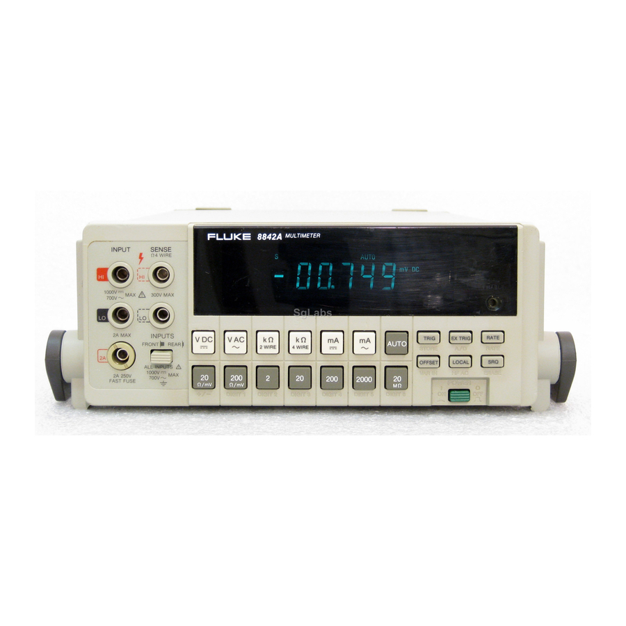
Page 30: Front Panel Features
Operating Instructions OPERATING FEATURES Note that the VAC and mA AC functions are available only with the True RMS AC option. If this option is absent, pressing the VAC and mA AC function buttons causes the 8842A to briefly display an error message (ERROR 30). FUNCTION BUTTONS: DC Volts 4-Wire Ohms... - Page 31 8842A Instruction Manual TRIG triggers a new reading. EXT TRIG toggles between internal Enabled in external trigger mode. and external trigger modes RATE cycles between slow, medium and fast reading rates. Automatically selects the optimum filter for each reading rate. SRQ generates a service request over the IEEE- 488 bus if enabled by the SRQ mask (IEEE-488 Interface option only).
-
Page 32: Rear Panel Features
4 WIRE TALK EXT TRIG SAMPLE SH1, AH1, T5, L4, SR1, RL1, ONLY 10V MAX COMPLETE DC1, DT1, PP0, C0, E1 240V JOHN FLUKE MFG. CO., INC. IEEE-05 LINE 220V EVERETT, WA MADE IN U.S.A. AC-09 120V 100V 1000V 300V MAX... -
Page 33: Typical Error Messages
8842A Instruction Manual 2-10. Display Features The 8842A features a vacuum fluorescent display with a numeric field and annunciators. The annunciators are explained in Figure 2-5. 2-11. Error Messages If the 8842A detects an operator error or an internal failure, it displays an error message for about 2-1/2 seconds and then resumes normal operation. -
Page 34: Error Codes
Operating Instructions OPERATING FEATURES Table 2-1. Error Codes ERROR MEANING ERROR CODE MEANING CODE ANALOG SELF-TEST ERRORS OPERATION ERRORS 200 VAC, Zero AC funtions availible only with 8842A-09 True RMS AC option. 700 VAC, Zero mA AC or mA DC funtion selected while REAR inputs selected. -
Page 35: Overrange Indication
01 through 29 correspond to the self-tests.) If self-test errors are displayed even when the input terminals are disconnected, there may be a hardware problem in your 8842A. In that event, refer to the Maintenance section or contact your local Fluke representative. -
Page 36: Manual Range
Operating Instructions OPERATING FEATURES 2-16. MANUAL RANGE In manual range, the 8842A remains fixed in the selected range until you select another range or press AUTO. If you select a range which is not valid for the present function, or select a function which is not valid for the present range, the 8842A selects the nearest valid range. -
Page 37: Overrange Indication
8842A Instruction Manual In the continuous trigger mode, the actual number of readings displayed per second for each reading rate is determined by the line-power frequency. At power-up, the 8842A senses the line-power frequency and adjusts the analog-to-digital converter timing characteristics for optimum normal-mode noise rejection. -
Page 38: Making Measurements
Operating Instructions MAKING MEASUREMENTS 2-24. MAKING MEASUREMENTS 2-25. Input Overload Protection Limits WARNING TO AVOID SHOCK HAZARD AND/OR INSTRUMENT DAMAGE, DO NOTAPPLY INPUT POTENTIALS THAT EXCEED THE INPUT OVERLOAD LIMITS SHOWN IN TABLE 2-2. The 8842A is protected against input overloads up to the limits shown in Table 2-2. Exceeding these limits may damage the instrument and/or pose a shock hazard. -
Page 39: Offset Measurements
8842A Instruction Manual To replace the front panel fuse, first remove the test leads. Then press in the lip of the 2A input terminal slightly and rotate it 1/4-turn counterclockwise. Spring tension will force the fuse and fuse holder out of the front panel. The internal 3A fuse should be replaced only by qualified service personnel. -
Page 40: External Cleaning
Operating Instructions EXTERNAL CLEANING f2-09.wmf Figure 2-9. Measuring Voltage and Resistance f2-10.wmf Figure 2-10. Measuring Current 2-30. EXTERNAL CLEANING WARNING TO AVOID ELECTRIC SHOCK OR INSTRUMENT DAMAGE, NEVER GET WATER INSIDE THE CASE. TO AVOID INSTRUMENT DAMAGE, NEVER APPLY SOLVENTS TO THE INSTRUMENT. - Page 41 8842A Instruction Manual 2-16...
-
Page 42: Remote Programming
Chapter 3 Remote Programming Title Page 3-1. INTRODUCTION................3-3 3-2. CAPABILITIES ...................3-3 3-3. BUS SET-UP PROCEDURE ...............3-3 3-4. AN OVERVIEW OF REMOTE OPERATION ........3-4 3-5. A NOTE ABOUT EXAMPLES............3-6 3-6. DEVICE-DEPENDENT COMMAND SET ........3-6 3-7. Bn (Offset Commands) ..............3-9 3-8. Cn (Calibration Commands) ............3-9 3-9. - Page 43 8842A Instruction Manual 3-35. ? (Single-Trigger Command) ............3-20 3-36. INPUT SYNTAX .................3-20 3-37. Definitions..................3-21 3-38. Input Processing................3-21 3-39. Syntax Rules ..................3-23 3-40. OUTPUT DATA ..................3-24 3-41. Loading Output Data................3-24 3-42. Types of Output Data ...............3-25 3-43. Numeric Data and Error Messages...........3-25 3-44.
-
Page 44: Introduction
This manual assumes you know the basics of the IEEE-488 interface bus. For an introduction to the bus, request Fluke Application Bulletin AB-36, "IEEE Standard 488- 1978 Digital Interface for Programmable Instrumentation." 3-2. CAPABILITIES The IEEE-488 Interface provides remote control of all front panel controls except for the POWER, CAL ENABLE, and FRONT/REAR switches. -
Page 45: An Overview Of Remote Operation
8842A Instruction Manual A4 A3 A2 A1 A5 A4 A3 A2 A1 A5 A4 A3 A2 A1 Not allowed TALK ONLY X = setting does not matter f3-01.wmf Figure 3-1. IEEE-488 Address Selection Whenever the 8842A is in the local state, the IEEE-488 address can be displayed on the front panel by pressing the LOCAL button. -
Page 46: Remote Operation Block Diagram
Remote Programming AN OVERVIEW OF REMOTE OPERATION f3-02.wmf Figure 3-2. Remote Operation Block Diagram... -
Page 47: A Note About Examples
In the examples in this manual, device-dependent commands are shown enclosed within quotation marks, as they would be entered in Fluke BASIC. For clarity, the commands are also separated by spaces. However, the spaces are are not necessary and may be omitted. -
Page 48: Commands Which Correspond To The Front Panel
Remote Programming DEVICE-DEPENDENT COMMAND SET TRIGGER COMMANDS Trigger Measurement GET Trigger and Execute TRIGGER MODE COMMANDS Continuous Trigger T1-T4 External Trigger DISPLAY COMMANDS READING RATE SUFFIX COMMANDS D0 Normal Display COMMANDS Y0 Disable Suffix D1 Blank Display S0 Slow Y1 Enable Suffix S1 Medium S2 Fast RANGE COMMANDS... -
Page 49: Device-Dependent Command Set
8842A Instruction Manual FUNCTON COMMANDS TERMINATOR COMMANDS VDC (Default) Enable CR LF EOI (Default) Enable CR LF Only 2 WIRE k Enable CR EOI Only 4 WIRE k Enable CR Only MA DC Enable LF EOI Only MA AC Enable LF Only RANGE COMMANDS Disable All Output Terminators Autorange... -
Page 50: Bn (Offset Commands)
Remote Programming DEVICE-DEPENDENT COMMAND SET Device-dependent commands are device-dependent messages. For the 8842A to receive them, they must be sent over the IEEE-488 bus when the 8842A is in remote and has been addressed as a listener. The following paragraphs describe the device-dependent commands in alphabetical order. Special characters (* and ?) are described last. -
Page 51: Fn (Function Commands)
8842A Instruction Manual 3-10. Fn (Function Commands) The function commands duplicate the front panel function buttons. The 8842A defaults to F1 on power-up and on any device-clear command (*, DCL, or SDC). If F0 is sent to the 8842A, it is internally converted to F1. The function setting can be read using the G0 command. -
Page 52: Status Data
10yw 0 output suffix disabled 1 output suffix enabled 0 – 7 as in Terminator commands (Wn) 10nn nn represents error code (See Table 2-1) FLUKE, Mmmmm = 8842A mmmmm, Vn.n = IEEE-488 Interface software version number 0, Vn.n The output data from some Get commands starts with a leading 1 or 10. This prevents the controller from suppressing leading zeroes and gives a uniform four-character length to all instrument configuration data (the data from Get commands G0, G4, G5, G6, and G7). -
Page 53: G0 (Get Instrument Configuration)
8842A Instruction Manual 3-12. G0 (Get Instrument Configuration) The G0 command copies the 8842A function, range, reading rate, and trigger mode into the output buffer in the format shown in Figure 3-6. The four digits returned represent the arguments for the equivalent F, R, S, and T commands, as shown in Table 3-1. An example output string follows. -
Page 54: G3 (Get User-Defined Message)
Remote Programming DEVICE-DEPENDENT COMMAND SET 3-15. G3 (Get User-Defined Message) The G3 command loads the output buffer with the user-defined message stored in calibration memory during the calibration procedure. The message consists of 16 ASCII characters, as shown in Figure 3-6. The message is stored in calibration memory during calibration using the P3 command. -
Page 55: G5 (Get Iab Status)
8842A Instruction Manual 3-17. G5 (Get IAB Status) The G5 command loads the output buffer with the IAB status in the format shown in Figure 3-6. As Table 3-1 explains, the IAB status is a four-character string which indicates the status of the FRONT/REAR switch (front or rear analog inputs selected), the autorange feature (autorange on or off), and the OFFSET feature (OFFSET on or off). -
Page 56: G8 (Get Instrument Identification)
IEEE-488 interface software. Example Explanation FLUKE,8842A,0,V4.0 CR LF This instrument is a Fluke 8842A with IEEE- 488 interface software version 4.0. 3-21. N (Numeric Entry Command) Format Explanation N<numeric entry>... -
Page 57: P1 (Put Srq Mask)
8842A Instruction Manual "N3120 P0" Identical to F3 R1 S2 T0. Selects 2 WIRE k function, 200 range, fast sample rate, continuous trigger. The P0 command allows broadside loading of the Function, Range, Reading Rate, and Trigger Mode commands (F, R, S, and T). The codes for these commands are listed in Figure 3-5. -
Page 58: P3 (Put User-Defined Message)
Remote Programming DEVICE-DEPENDENT COMMAND SET etc. All of these strings result in the same value being used for the next calibration step. For complete information about remote calibration, refer to the Maintenance section. Numeric values exceeding full scale and negative values for ohms and AC generate error messages. -
Page 59: Trigger Selection Logic Diagram
8842A Instruction Manual 3-29. Tn (Trigger Mode Commands) The Trigger Mode commands duplicate the front panel EX TRIG button. In addition, the commands can enable or disable the rear panel trigger and the automatic settling time delay. Figure 3-7 illustrates how to select among the five types of triggers: continuous trigger, front panel trigger, rear panel trigger, and two bus triggers. -
Page 60: Wn (Terminator Commands)
Remote Programming DEVICE-DEPENDENT COMMAND SET The trigger mode can be read using the G0 command. The 8842A defaults to T0 on both power-up and any device-clear command (*, DCL, or SDC). 3-30. Wn (Terminator Commands) The Terminator commands select what terminators the 8842A appends to every output string. -
Page 61: Device-Clear Command)
8842A Instruction Manual Error messages are indicated by an exponent of +21. For more about error messages, see paragraph 3-40. Since the 8842A is reset at the end of the self-tests, the Z0 command should be the last command in a given command string. The 8842A will ignore any subsequent commands in the same command string. -
Page 62: Definitions
In some instances, a terminator is automatically transmitted at the end of the controller’s output string. For example, in Fluke BASIC, the PRINT statement always finishes with a CR LF pair. If a controller does not have this feature, the programmer must transmit a terminator explicitly. -
Page 63: Interpretation Of Messages
8842A Instruction Manual DEVICE-DEPENDENT MESSAGES Single-character Commands Bn Cn Dn Fn Gn Pn Rn Sn Wn Xn Yn Zn Each of these commands requires the single numeric digit (n). Numeric-entry Characters NE. + - 0123456789 These characters are used for entering numbers Terminators Carriage Return Line Feed... -
Page 64: Syntax Rules
Rule 3 is most evident in the external trigger mode, and is best demonstrated by a programming example. The following program is written first incorrectly, and then correctly, in Fluke BASIC using the 1722A Instrument Controller. Incorrect example PRINT @3, "T1 ?"... -
Page 65: Output Data
8842A Instruction Manual In this incorrect example, the INPUT statement is located incorrectly for reading the measurement data from line 100. The new input command string "F4" disallows the reading of data from the output buffer. Correct example PRINT @3, "T1 ?" INPUT @3, A PRINT @3, "F4"... -
Page 66: Types Of Output Data
Remote Programming OUTPUT DATA Because the 8842A gives priority to input processing, it completely processes all characters in the input buffer before it loads the output buffer. When the output buffer is loaded, the Data Available bit in the serial poll register is set true. Data from the output buffer is not actually loaded onto the IEEE-488 bus until the controller addresses the 8842A as a talker. -
Page 67: Overrange Indication
8842A Instruction Manual NOTE In the fast (F) reading rate, the least significant digit is always zero, and should be disregarded when interpreting accuracy specifications. 3-45. OVERRANGE INDICATION If a reading is overrange ( 200,000 counts), the measurement data has the following format: ±9.99999E+9 <suffix>... -
Page 68: Service Requests
Remote Programming SERVICE REQUESTS 1. Status data (from G0, G1, G3, G4, G5, G6, G7 and G8) 2. Error messages (if an error exists) 3. Numeric data (from G2 or a trigger) This means that an error message always overrides numeric data, but status data is sent even in the presence of an error. -
Page 69: The Srq Mask
8842A Instruction Manual BIT: 8 DATA CAL STEP FRONT OVER- ERROR AVAILIBLE COMPLETE PANEL SRQ RANGE DECIMAL VALUE: Name Cleared Overrange An overrange condition occurs Device command received, or Bus or Rear Panel Trigger, or Output buffer is read Not used Never Always Front panel SRQ... -
Page 70: Interface Messages
Remote Programming INTERFACE MESSAGES The SRQ mask can enable any combination of serial poll register bits 1 through 6. Its six- bit binary representation is ANDed bit-for-bit with serial poll register bits 1 through 6 whenever the output buffer is loaded. If any mask-enabled bit in the serial poll register comes true, the RQS bit (bit 7) is set true, generating a service request. -
Page 71: Addressed Commands
8842A Instruction Manual Interface Clear -- A uniline message which clears only the interface (not the 8842A) by placing it in a known quiescent state. Remote Enable -- A uniline message which, when received with MLA, switches the 8842A to remote. When REN is set false, the 8842A switches to local and removes local lockout. -
Page 72: Remote Calibration
Remote Programming REMOTE CALIBRATION 6. Configure the 8842A with the front panel controls. The 8842A reads the TALK ONLY bit switch on power-up and when it receives the interface command IFC. You can therefore set the TALK ONLY switch to 1 after power- up as long as you then send the 8842A the IFC command. -
Page 73: Example Programs
8842A Instruction Manual Table 3-3. Immediate-Mode Commands for Various Controllers FUNTION FLUKE-BASIC on HP-HPL on HP-BASIC on TEK-BASIC on PERFORMED 1720A or 1722A HP9825 HP9816-PC and HP- 4051 Graphics Calculator 85 Calculator System INITIALIZE Port INIT PORT 0 cli 7... -
Page 74: Example Programs
Remote Programming EXAMPLE PROGRAMS f3-10.wmf Figure 3-9. Example Program 3-33... -
Page 75: Example Program: Taking Readings With Local Control
8842A Instruction Manual f3-11.wmf Figure 3-10. Example Program: Taking Readings with Local Control 3-34... -
Page 76: Example Program: Using The Serial Poll Register
Remote Programming EXAMPLE PROGRAMS f3-12.wmf Figure 3-11. Example Program: Using the Serial Poll Register 3-35... -
Page 77: Example Program: Record Errors During Selftest
8842A Instruction Manual f3-13.wmf Figure 3-12. Example Program: Record Errors During Selftest 3-36... -
Page 78: Example Programs: Using The Ibm Pc
Remote Programming EXAMPLE PROGRAMS f3-14_01.wmf Figure 3-13. Example Programs: Using the IBM PC 3-37... - Page 79 8842A Instruction Manual f3-14_01.wmf Figure 3-14. Example Programs: Using the IBM PC (cont) 3-38...
- Page 80 Remote Programming EXAMPLE PROGRAMS f3-14_02.wmf Figure 3-14. Example Programs: Using the IBM PC (cont) 3-39...
- Page 81 8842A Instruction Manual f3-14_03.wmf Figure 3-14. Example Programs: Using the IBM PC (cont) 3-40...
- Page 82 Remote Programming EXAMPLE PROGRAMS f3-14_04.wmf Figure 3-14. Example Programs: Using the IBM PC (cont) 3-41...
- Page 83 8842A Instruction Manual f3-14_05.wmf Figure 3-14. Example Programs: Using the IBM PC (cont) 3-42...
- Page 84 Remote Programming EXAMPLE PROGRAMS f3-14_06.wmf Figure 3-14. Example Programs: Using the IBM PC (cont) 3-43...
- Page 85 8842A Instruction Manual f3-14_07.wmf Figure 3-14. Example Programs: Using the IBM PC (cont) 3-44...
- Page 86 Remote Programming EXAMPLE PROGRAMS f3-14_08.wmf Figure 3-14. Example Programs: Using the IBM PC (cont) 3-45...
- Page 87 8842A Instruction Manual f3-14_09.wmf Figure 3-14. Example Programs: Using the IBM PC (cont) 3-46...
- Page 88 Remote Programming EXAMPLE PROGRAMS f3-14_10.wmf Figure 3-14. Example Programs: Using the IBM PC (cont) 3-47...
- Page 89 8842A Instruction Manual f3-14_11.wmf Figure 3-14. Example Programs: Using the IBM PC (cont) 3-48...
-
Page 90: Ascii/Ieee Std 488-1978 Bus Codes
Remote Programming EXAMPLE PROGRAMS Table 3-4. ASCII/IEEE Std 488-1978 Bus Codes 3-49... - Page 91 8842A Instruction Manual NOTE For the examples using the Fluke 1720A or 1722A, the 8842A is plugged into port 0. The port is initialized by the INIT statement, which sends IFC (interface clear). 3-50...
-
Page 92: Measurement Tutorial
Chapter 4 Measurement Tutorial Title Page 4-1. INTRODUCTION................4-2 4-2. DC VOLTAGE MEASUREMENT .............4-2 4-3. Circuit Loading Error...............4-2 4-4. Input Bias Current Error..............4-3 4-5. RESISTANCE MEASUREMENT ............4-4 4-6. 2-Wire Ohms..................4-4 4-7. Correcting for Test Lead Resistance in 2-Wire Ohms .....4-5 4-8. 4-Wire Ohms..................4-5 4-9. -
Page 93: Introduction
8842A Instruction Manual 4-1. INTRODUCTION This section discusses considerations and techniques to help you use the 8842A effectively. Among other things, this section discusses sources of error which are an inherent part of the measurement process and which occur for all multimeters. By understanding why and when these errors occur, and by knowing how and when to correct for them, you can make accurate measurements with confidence. -
Page 94: Input Bias Current Error
Measurement Tutorial DC VOLTAGE MEASUREMENT The input impedance of the 8842A is 10 M in the 200V and 1000V dc ranges, and is greater than 10,000 M in the 20 mV, 200 mV, 2V, and 20V ranges. Therefore, for the 8842A, circuit loading error is less than 0.01% as long as the source impedance is less than 1 M in the 20 mV, 200 mV, 2V, and 20V ranges, and less than 1 k in the 200V and 1000V ranges. -
Page 95: Resistance Measurement
8842A Instruction Manual 3. Allow the displayed reading to settle. 4. Press the OFFSET button. 5. Remove the resistor. 6. Proceed with the desired measurement. Example: Measure a 1.5V source with 1 M source impedance, correcting for input bias current. 1. -
Page 96: Correcting For Test Lead Resistance In 2-Wire Ohms
Measurement Tutorial RESISTANCE MEASUREMENT The test current and full-scale voltage for each resistance range are shown in Table 4-1. Since the HI INPUT test lead is positive with respect to the LO INPUT lead, these test leads are not interchangeable when a semiconductor device is being measured. 4-7. -
Page 97: Ohms Test Current
8842A Instruction Manual f4-04.wmf Figure 4-4. Wire Ohms Measurement Table 4-1. Ohms Test Current RANGE TEST CURRENT FULL SCALE VOLTAGE 1 mA 0.02V 1 mA 0.2V 1 mA 2.0V 20 k 100 A 2.0V 200 k 10 A 2.0V 2000 k 10.0V 20 M 500 nA... -
Page 98: Applications Of The Ohms Functions
Measurement Tutorial RESISTANCE MEASUREMENT NOTE In the 2 M and 20 M ranges of 4-wire ohms, the voltage across the unknown resistance is sensed between the HI SENSE and LO INPUT terminals. Accuracy is not affected as long as the resistance of the LO INPUT lead is less than 10 in the 2 M range, and less than 100 in the 20 M range. -
Page 99: A Precision Current Source
8842A Instruction Manual 4-12. A PRECISION CURRENT SOURCE The ohms current source (the internal current source used in the ohms functions) makes a useful troubleshooting tool in itself. It has excellent linearity and temperature stability. Its compliance voltage is typically 5V in the lower five ohms ranges, and 12V in the upper two ohms ranges. -
Page 100: Reducing Thermal Voltages
Measurement Tutorial REDUCING THERMAL VOLTAGES f4-05.wmf Figure 4-5. Burden Voltage Error Calculation 4-14. REDUCING THERMAL VOLTAGES When making very low-level dc measurements, thermal voltages can present an additional source of error. Thermal voltages are the thermovoltaic potentials generated at the junction between dissimilar metals. Thermal voltages typically occur at binding posts and can be greater than 10 V. -
Page 101: Ac Voltage And Current Measurement
8842A Instruction Manual 4. Use caution when handling the circuit under test. 5. Wait for the circuit to reach thermal equilibrium. (Thermal voltages are generated only where there is a temperature gradient.) 4-15. AC VOLTAGE AND CURRENT MEASUREMENT When making precise measurements of ac voltage and current, there are several considerations in addition to those discussed under dc voltage and current measurement. -
Page 102: Waveform Comparison Chart
Measurement Tutorial AC VOLTAGE AND CURRENT MEASUREMENT f4-06.wmf Figure 4-6. Waveform Comparison Chart Since average-responding meters have been in use for so long, you may have accumulated test or reference data based on them. The conversion factors in Figure 4-6 should help you convert between the two measurement methods. -
Page 103: Crest Factor
8842A Instruction Manual 4-18. Crest Factor Crest factors are useful for expressing the ability of an instrument to measure a variety of waveforms accurately. The crest factor of a waveform is the ratio of its peak voltage to its rms voltage. (For waveforms where the positive and negative half-cycles have different peak voltages, the more extreme peak is used in computing the crest factor.) Crest factors start at 1.0 for square waves (for which the peak voltage equals the rms voltage) and increase for more "pointed"... -
Page 104: Combined Ac And Dc Measurements
Measurement Tutorial AC VOLTAGE AND CURRENT MEASUREMENT measurements, for instance, cannot be made with dc coupling. Remember, however, that when the 8842A measures signals with the ac functions, the reading on the display does not include the dc component (if one exists). For example, consider Figure 4-8, which shows a simple ac signal riding on a dc level. -
Page 105: Making Accurate Measurements On The 20 Mv And 20 Ranges
8842A Instruction Manual The zero-input error is quickly reduced when the input is increased. The rms converter error (a dc error) and the internally generated noise (a random ac error) are both uncorrelated with the input signal. Therefore, when a signal is applied, the resulting reading is not the simple addition of the signal and the zero-input error, but the square root of the sum of their squares. -
Page 106: Making Accurate High-Resistance Measurements
Measurement Tutorial MAKING ACCURATE HIGH-RESISTANCE MEASUREMENTS f4-10.wmf Figure 4-10. Shielding for Low Voltage Measurements For low-level resistance measurements, connect the test lead shielding as shown in Figure 4-11. Use the 4-wire ohms function to minimize the error caused by the resistance of the test leads. -
Page 107: Leakage Resistance In High Resistance Measurement
8842A Instruction Manual f4-12.wmf Figure 4-12. Leakage Resistance in High Resistance Measurement 4-16... -
Page 108: Theory Of Operation
Chapter 5 Theory of Operation Title Page 5-1. INTRODUCTION................5-3 5-2. OVERALL FUNCTIONAL DESCRIPTION ........5-3 5-3. DETAILED CIRCUIT DESCRIPTION ..........5-4 5-4. DC SCALING ..................5-4 5-5. VDC Scaling ..................5-6 5-6. VDC Protection................5-7 5-7. mA DC Scaling ................5-7 5-8. - Page 109 8842A Instruction Manual 5-36. POWER SUPPLY ................5-25 5-37. IEEE-488 INTERFACE (OPTION -05)..........5-26 5-38. Out-Guard Microcomputer............... 5-26 5-39. Guard Crossing................. 5-26 5-40. Bus Interface Circuitry..............5-26 5-41. Signal Conditioning ................. 5-27 5-42. IEEE-488 Interface Power Supply ........... 5-27 5-43. TRUE RMS AC (OPTION -09) ............
-
Page 110: Introduction
Theory of Operation INTRODUCTION 5-1. INTRODUCTION This section presents an overall functional description of the 8842A, followed by a detailed circuit description. The descriptions are supported by simplified schematics in text and by the complete schematics in Section 10. 5-2. OVERALL FUNCTIONAL DESCRIPTION A functional block diagram of the 8842A is shown in Figure 5-1. -
Page 111: Detailed Circuit Description
8842A Instruction Manual 5-3. DETAILED CIRCUIT DESCRIPTION The following paragraphs give a detailed circuit description of each of the functional blocks in Figure 5-1. For clarity, measurement ranges are referred to as r1, r2, r3, etc., where r1 is the lowest possible range, r2 the next higher range, and so on. Pins are designated by the respective integrated circuit (e.g., U101-7 for U101 pin 7). -
Page 112: Overall Functional Block Diagram
Theory of Operation DC SCALING f5-01.wmf Figure 5-1. Overall Functional Block Diagram... -
Page 113: Vdc Scaling
8842A Instruction Manual 5-5. VDC Scaling Scaling is performed in the VDC function by two precision resistors networks (Z301 and Z302). These components are configured by relay K301, switching transistor Q311, and quad analog switches U302A and U301B to provide the correct scaling for each range. Voltage follower U306 provides high input impedance for the 20V dc range. -
Page 114: Vdc Protection
Theory of Operation DC SCALING In the 20 mV, 200 mV and and 2V ranges, the input voltage is applied directly to the T/H Amplifier via Q310, Q311, and U301B. In the 20 mV range, the T/H Amplifier has a gain of 100;... -
Page 115: Track/Hold Circuit
8842A Instruction Manual 5-9. TRACK/HOLD CIRCUIT The Track/Hold (T/H) circuit presents a stable voltage to the A/D Converter during the input period of the A/D conversion cycle. The circuit also provides a gain of 100 in the 20 mV, 20 and 200 mA ranges, and a gain of 10 in the 200 mV dc, 200 , and 2000 mA dc ranges. -
Page 116: Track/Hold Circuit Configurations
Theory of Operation TRACK/HOLD CIRCUIT f5-04.wmf Figure 5-4. Track/Hold Circuit Configurations... -
Page 117: Track Configuration
8842A Instruction Manual f5-05.wmf Figure 5-5. Timing Diagram for One A/D Cycle 5-10. Track Configuration In the track configuration (Figure 5-4A), the T/H circuit functions as a non-inverting buffer. The voltage on C308 tracks the scaled dc input voltage. 5-10... -
Page 118: Settling Configuration
Theory of Operation PRECISION VOLTAGE REFERENCE 5-11. Settling Configuration The circuit assumes a settling configuration between the track and hold configurations. The circuit assumes the configuration in Figure 5-4B for unity gain and the configuration in Figure 5-4C for gain of 10. During this time the DC Scaling circuit is still connected to the T/H amp. -
Page 119: Ohms Current Source
8842A Instruction Manual Resistor R701, precision resistor network Z701, and transistor/zener diode combination U701 are produced as a matched set so that the output of U702A is precisely -7.00000V. This output is remotely sensed at the pins of the custom A/D IC (U101). Diode CR701 prevents the output from going positive at power-up. -
Page 120: Ohms Protection
Theory of Operation OHMS PROTECTION The second stage (U404, precision resistor network Z401, and analog switches U402 and U403) is a current amplifier whose gain is controlled by the In-Guard C. The In-Guard C sets the output current for each range by controlling U402 and U403. (See switch state table in Figure 5-7.) 5-16. -
Page 121: Ohms Scaling
8842A Instruction Manual f5-08.wmf Figure 5-8. Ohms Scaling 5-14... -
Page 122: 4-Wire Ohms
2000 k range and less than 100 in the 20 M range. 5-20. A/D CONVERTER The Analog-to-Digital (A/D) Converter (Figure 5-9) uses Fluke’s patented recirculating remainder technique. An input voltage (Vin) is compared to the output of the precision Digital-to-Analog Converter (DAC). -
Page 123: Analog-To-Digital Converter
8842A Instruction Manual f5-09.wmf Figure 5-9. Analog-to-Digital Converter The conversion process is broken up into an autozero period followed by five measurement intervals. (A timing diagram is shown in Figure 5-5.) Six bits of the final A/D sample are obtained during each interval. During the first compare period (shown in Figure 5-9), the A/D Converter determines the value of the scaled input voltage (Vin) by comparing Vin to the output of the DAC. -
Page 124: Timing/Data Control
Theory of Operation A/D CONVERTER f5-10.wmf Figure 5-10. First Remainder-Store Period This five-interval process thus generates five nibbles which are processed by the In- Guard C to produce one A/D sample. After the fifth nibble is generated, U101 interrupts the In-Guard C over line INT. The In-Guard C then pulls line CS7 low five times, causing U101 to send the C the five (six-bit) nibbles one-at-a-time over lines AD0- AD5. -
Page 125: A/D Amplifier
8842A Instruction Manual The bit-switches determine the output voltage of U102B by controlling the binary ladder network. The gain of U102B is set by the ratio of a precision feedback resistor (Z101-7, - 8) and the equivalent output resistance of the ladder network. 5-23. -
Page 126: Keyboard
Theory of Operation KEYBOARD f5-12.wmf Figure 5-12. Vacuum Fluorescent Display The Digital Controller sequentially enables the G lines by applying +30V dc (nominal). When a G line is enabled, electrons flow from the filament to the enabled grid. If a P line is enabled (i.e., raised to a nominal +30V dc by the Digital Controller), the electrons continue past the grid and strike the respective plate, causing it to glow. -
Page 127: Digital Controller Block Diagram
8842A Instruction Manual f5-13.wmf Figure 5-13. Digital Controller Block Diagram 5-20... -
Page 128: In-Guard Microcomputer
Theory of Operation DIGITAL CONTROLLER 5-28. In-Guard Microcomputer The In-Guard Microcomputer ( C) is a single-chip Z8 microcomputer containing 4K bytes of ROM, 144 bytes of RAM, a UART, and four 8-bit I/O ports. It communicates with the rest of the instrument via the internal bus and dedicated I/O lines. The In-Guard C is reset when pin 6 is pulled low either by C204 at power-up or by the watch-dog timer in the custom A/D IC (U101). -
Page 129: Read/Write Timing Diagrams For Internal Bus
8842A Instruction Manual f5-14.wmf Figure 5-14. Read/Write Timing Diagrams for Internal Bus 5-22... -
Page 130: Function And Range Control
Theory of Operation DIGITAL CONTROLLER 5-29. Function and Range Control The In-Guard C configures the DC Scaling circuit, the Track/Hold circuit, and the Ohms Current Source to provide the proper input switching, scaling, and filtering for each function, range, and reading rate. It does this by controlling dedicated output lines which control relays and FET switches, and by sending configuration codes out on the bus. -
Page 131: Keyboard/Display Control
8842A Instruction Manual 5-32. Keyboard/Display Control Keyboard/Display Controller U212 communicates with the In-Guard C over the internal bus. During a C write cycle, address line A0 tells U212 whether to consider data being sent by the C as configuration commands or as display data. Display data is stored in the Keyboard/Display Controller, which automatically scans the display. -
Page 132: Power Supply
Theory of Operation POWER SUPPLY The circuit in Figure 5-15 has two stable states, corresponding to output high (+5V) and output low (0V). If the output is high, the voltage present at the non-inverting input of op amp A is approximately +140 mV. Since the inputs to op amps A and B are inverted, their outputs are always in opposite states. -
Page 133: Ieee-488 Interface (Option -05)
8842A Instruction Manual 5-37. IEEE-488 INTERFACE (OPTION -05) The IEEE-488 Interface has five major parts, as shown in the block diagram in Figure 5- 16. All components are contained in a single printed circuit assembly (PCA). Reference designations are numbered in the 900 series. f5-16.wmf Figure 5-16. -
Page 134: Signal Conditioning
Theory of Operation TRUE RMS AC (OPTION -09) 5-41. Signal Conditioning The SAMPLE COMPLETE and EXT TRIG signals (J903 and J904) are conditioned by U909. Diodes CR903, CR904, CR905, and CR906 and resistors R917 and R918 provide protection from excessive voltages. Jumpers E902 and E903 allow selection of the polarity of the EXT TRIG signal. -
Page 135: Ma Ac Scaling
8842A Instruction Manual U806A, U806B, and a voltage divider (R804 and R805) provide gain which is selected for each range by the analog switches in U804. The configuration for each range is shown in Figure 5-17. (In this figure, the CMOS analog switches are represented by mechanical switches.) When U806A is not used, its non-inverting input is grounded by Q804. - Page 136 A Message From Fluke Corporation Some semiconductors and custom IC's can be damaged by electrostatic discharge during handling. This notice explains how you can minimize the chances of destroying such devices 1. Knowing that there is a problem.
- Page 137 8. WHEN REMOVING PLUG-IN ASSEMBLIES 5. USE STATIC SHIELDING CONTAINERS FOR HANDLE ONLY BY NON-CONDUCTIVE HANDLING AND TRANSPORT. EDGES AND NEVER TOUCH OPEN EDGE CONNECTOR EXCEPT AT STATIC-FREE WORK STATION. PLACING SHORTING STRIPS ON EDGE CONNECTOR HELPS PROTECT INSTALLED S.S. DEVICES. 6.
-
Page 138: Maintenance
Chapter 6 Maintenance Title Page 6-1. INTRODUCTION.................. 6-3 6-2. PERFORMANCE TEST ................ 6-4 6-3. Diagnostic Self-Tests ................. 6-4 6-4. DC Voltage Test................. 6-5 6-5. AC Voltage Test (Option -09 Only)........... 6-7 6-6. Resistance Test................... 6-8 6-7. DC Current Test ................. 6-9 6-8. - Page 139 8842A Instruction Manual 6-35. EXTERNAL TRIGGER POLARITY SELECTION (Option -05 Only) 6-36 6-36. TROUBLESHOOTING ................. 6-36 6-37. Initial Troubleshooting Procedure............6-36 6-38. Diagnostic Self-Tests ................. 6-41 6-39. Self-Test Descriptions................ 6-42 6-40. Digital Controller Troubleshooting............ 6-45 6-41. IN-GUARD MICROCOMPUTER SYSTEM ....... 6-45 6-48.
-
Page 140: Introduction
Fluke 720A Ratio Range: 0-1.0 Absolute Linearity: ± 1 ppm of input at dial setting Resistor Calibrator Resistance Accuracy: 0.0005% Fluke 5700A or Fluke 5450A, ESI DB62 DC Current Source Accuracy: ±0.025% Fluke 5700A or Fluke 5100B Oscilloscope General porpose, 60 MHz, with 10... -
Page 141: Performance Test
8842A Instruction Manual AC Calibrator Fluke 5700A and Fluke 5725A Minimum Required Accuracy (By Range) Frequency Range 1, 10, 100 mV 1, 10, 100V 1000V 20 Hz – 30 Hz .1 + .005 .1 + .005 .12 + .005 30 Hz – 20 kHz .02 + 10... -
Page 142: Dc Voltage Test
3. Connect the DC Calibrator (see Table 6-1) to provide a voltage input to the HI and LO INPUT terminals. Connections for the Kelvin-Varley Voltage Divider and the Fluke 5440A are shown in Figure 6-1. 4. For each step in Table 6-2, select the indicated range, set the DC Calibrator for the specified input, and verify that the displayed reading is within the limits shown for each reading rate. -
Page 143: Dc Calibration Connections
8842A Instruction Manual f6-01.wmf Figure 6-1. DC Calibration Connections Table 6-2. DC Voltage Test Displayed Reading STEP RANGE INPUT SLOW MEDIUM FAST (V dc) 20 mV -0.0030 +0.0030 -0.0050 +0.0050 -0.030 +0.030 (short) 200 mV -00.003 +00.003 -00.005 +00.005 -00.03 +00.03 (short) 2V, 20V,... -
Page 144: Low- And Mid-Frequency Ac Voltage Test
Maintenance PERFORMANCE TEST 6-5. AC Voltage Test (Option -09 Only) The following procedure may be used to verify the accuracy of the VAC function: 1. Ensure the 8842A is on and warmed up for at least 1 hour. 2. Select the VAC function and the slow (S) reading rate. 3. -
Page 145: Resistance Test
8842A Instruction Manual Table 6-4. High-Frequency AC Voltage Test STEP RANGE INPUT ERROR TEST LIMITS (IN VOLTS) NUMBER VOLTAGE FREQUENCY COUNTS 200 mV 0.010000V 50 kHz 09.831 mVAC 10.169 mVAC 200 mV 0.010000V 100 kHz 09.650 mVAC 10.350 mVAC 0.10000V 100 kHz 0.09650 VAC 0.10350 VAC... -
Page 146: Dc Current Test
Maintenance PERFORMANCE TEST Table 6-5. Resistance Test Step Range Input Error From Input (in counts) (Nominal) Slow Medium Fast (short) ±40 ±60 ±20 ±49 ±69 ±21 (short) ±4 ±6 ±3 ±11 ±13 ±4 (short) ±3 ±5 ±2 ±8 ±10 ±3 20 k (short) ±3... -
Page 147: Ac Current Test (Option -09 Only)
If an ac current source is not available, the functionality of the 8842A can be checked at 10 mA by using a Fluke 5200A set at 100V and connected to the 8842A 2A terminal through a 10 k , 2W, 1% resistor. -
Page 148: Basic Calibration Procedure
Maintenance CALIBRATION 6-10. Basic Calibration Procedure The basic calibration procedure consists of the following four parts. These parts must be performed in the order shown. 1. Initial Procedure. 2. A/D Calibration. 3. Offset and Gain Calibration for each function and range. 4. -
Page 149: A/D Calibration
8842A Instruction Manual f6-03.wmf Figure 6-3. Calibration Functions The following functions are inappropriate during calibration, and are therefore unavailable: Offset Autoranging External Trigger Front Panel Trigger Front panel SRQ (Under local control) Diagnostic self-tests 6-12. A/D CALIBRATION The A/D Calibration procedure calibrates the analog-to-digital converter for offset, gain and linearity. -
Page 150: A/D Calibration Steps
Maintenance CALIBRATION 2. Each time the 8842A prompts you for a reference source, apply the requested source to the HI and LO INPUT terminals, and press the STORE button. When STORE is pressed, the numeric display field blanks while the 8842A performs the necessary calculations. -
Page 151: Offset And Gain Calibration
8842A Instruction Manual The A/D Calibration procedure is an iterative process. Each pass through the procedure uses the constants stored previously and improves them. Normally, one pass is adequate. However, if the calibration memory has been erased or replaced, or the A/D Converter has undergone repair, the A/D Calibration procedure must be performed twice. -
Page 152: High-Frequency Ac Calibration
Maintenance CALIBRATION NOTE To use reference sources that differ from the prompted values, see Storing Variable Inputs later in this section. 4. After the last range is calibrated, the 8842A begins taking readings in the highest range so that you may verify its calibration. (The CAL annunciator remains on.) To verify the calibration for the other ranges, press the corresponding range button. -
Page 153: Advanced Features And Special Considerations
8842A Instruction Manual 5. The calibration procedure is now completed. Exit the calibration mode by pressing the CAL ENABLE switch, and attach a calibration certification sticker over the CAL ENABLE switch. 6-15. Advanced Features and Special Considerations Table 6-11. High-Frequency AC Calibration Steps STEP DISPLAYED PROMPT 100.0 mV AC... -
Page 154: Calibrating Individual Ranges
Maintenance CALIBRATION 6-17. CALIBRATING INDIVIDUAL RANGES During Offset and Gain and High-Frequency AC Calibration, it is possible to calibrate individually selected ranges. This feature does not apply to the mA DC and mA AC functions and is not permitted during A/D Calibration. To calibrate an individual range, proceed as follows: 1. -
Page 155: Erasing Calibration Memory
8842A Instruction Manual 1. If you just completed the Offset and Gain or High-Frequency AC Calibration for an entire function (not just one range), the range buttons can be used to change ranges in order to verify all ranges were calibrated correctly. 2. -
Page 156: Ac Calibration At Other Frequencies
1 kHz. 6-22. OPTIMIZING USE OF THE 5450A If the Fluke 5450A Resistance Calibrator is used to calibrate the 2-wire ohms function, the following procedure is recommended to optimize the calibration of the lowest two ranges. -
Page 157: Optimizing Use Of The 5450A
8842A Instruction Manual readings. (In remote calibration, the averaged value can be stored in the controller.) Record the value. 4. Select the "100 " output from the 5450A, and measure this value as in step 3. 5. Find and record the numerical difference between the values calculated in steps 3 and 4. -
Page 158: Commands Used During Remote Calibration
Maintenance CALIBRATION Table 6-14. Commands Used During remote Calibration FRONT PANEL CORRESPONDING COMMENTS FEATURE COMMAND Display Loads the calibration prompt into the output buffer. Not valid when the 8842A is taking verification readings. Function Buttons F1 through F6 In the calibration mode, these select the Offset and Gain Calibration procedure for the corresponding funtion. - Page 159 8842A Instruction Manual 1. In remote calibration, you can store a 16-character message in the calibration memory which can be read by the system controller. Possible uses include storing the calibration date, instrument ID, etc. 2. Although some buttons are ignored in local calibration (e.g., the AUTO button), the corresponding remote commands (e.g., R0) load the output buffer with an error message.
-
Page 160: Timing Considerations
Maintenance CALIBRATION 6-24. TIMING CONSIDERATIONS Table 6-15. Error Numbers Which Are Displayed When Commands Are Not Valid COMMAND NORMAL SELFTEST CALIBRATION MODE MODE A/D CAL OFFSET & HF AC CAL VERIFICAT GAIN CAL ION MODE R1-6 6-23... -
Page 161: Remote Erasure
An example A/D calibration program is shown in Figure 6-5. The program is written in Fluke BASIC for the Fluke 1722A Instrument Controller. It uses the Fluke 5440A Direct Voltage Calibrator to perform and then verify the A/D Calibration procedure. In this program, the 8842A is at bus address 1, and the 5440A is at bus address 7. -
Page 162: Disassembly Procedure
Maintenance DISASSEMBLY PROCEDURE f6-05.wmf Figure 6-5. Example A/D Calibration Program 6-27. DISASSEMBLY PROCEDURE WARNING TO AVOID ELECTRIC SHOCK, REMOVE THE POWER CORD AND TEST LEADS BEFORE DISASSEMBLING THE INSTRUMENT. OPENING COVERS MAY EXPOSE LIVE PARTS. CAUTION To avoid contaminating the printed circuit assemblies (PCAs), handle the PCAs by their edges. -
Page 163: Case Removal
8842A Instruction Manual 6-28. Case Removal 1. Remove the grounding screw from the bottom of the case. Remove two rear bezel mounting screws. (See Figure 6-6A.) 2. While holding the front panel, slide the case and rear bezel off the chassis (See Figure 6-6B). - Page 164 Maintenance DISASSEMBLY PROCEDURE f6-06_2.wmf Figure 6-6. 8842A Disassembly (cont) 6-27...
- Page 165 8842A Instruction Manual f6-06_3.wmf Figure 6-6. 8842A Disassembly (cont) 6-28...
- Page 166 Maintenance DISASSEMBLY PROCEDURE f6-06_4.wmf Figure 6-6. 8842A Disassembly (cont) 6-29...
-
Page 167: True Rms Ac Pca Removal (Option -09 Only)
8842A Instruction Manual 6-29. True RMS AC PCA Removal (Option -09 Only) The True RMS AC PCA should be removed by reversing the last three steps in Figure 809-1 (see Section 8). 1. Release the True RMS AC PCA from the chassis by pulling the four plastic latches upward (Figure 809-1E). - Page 168 Maintenance DISASSEMBLY PROCEDURE b. Unplug the ribbon cable from the Main PCA and lift out the LINE SET PCA. 9. Remove the push rod for the CAL ENABLE switch as follows (Figure 6-6H): a. While supporting the white plunger of the CAL ENABLE switch with a finger, pop the push rod off the switch plunger by pulling the push rod directly upward.
-
Page 169: Front Panel Disassembly
8842A Instruction Manual 6-32. Front Panel Disassembly 1. Holding the chassis vertically (with the front panel downward), remove the mounting screws from the four corners of the Display PCA (Figure 6-7A). 2. Holding the chassis vertically (now standing the instrument on the rear panel), pull the front panel off the chassis and set it aside (Figure 6-7B). - Page 170 Maintenance REASSEMBLY PROCEDURE NOTE When installing the Main PCA, guide the rear ribbon cable around the shield connected to the rear panel so that the cable is next to the side of the chassis. Make certain that the cable is not pinched between the shield and the Main PCA.
-
Page 171: Front Panel Disassembly
8842A Instruction Manual f6-07.wmf Figure 6-7. Front Panel Disassembly 6-34... -
Page 172: Removing The Display Window
Maintenance REASSEMBLY PROCEDURE f6-08.wmf Figure 6-8. Removing the Display Window CAUTION Make certain that the CAL ENABLE switch shaft is in the out (disabled) position after the CAL ENABLE push rod is installed. If the 8842A is switched on with the CAL ENABLE switch in the enabled position, the 8842A may require recalibration. -
Page 173: Internal Fuse Replacement
Using the information in this section, a technician should be able to troubleshoot and repair the 8842A very efficiently. There is also a troubleshooting package available which utilizes the Fluke 9010A System Troubleshooter. The 8842A- 9000 Troubleshooting Kit is described in detail in Section 8. - Page 174 Maintenance TROUBLESHOOTING If the display lights up, perform the self-test by pressing the SRQ button for 3 seconds. (Remember, the input terminals must be disconnected from the test leads during the self- tests. Otherwise, the 8842A may indicate errors are present.) The test numbers will appear consecutively.
-
Page 175: Overall State Table
8842A Instruction Manual Table 6-16. Overall State Table t6-16_1.wmf 6-38... - Page 176 Maintenance TROUBLESHOOTING Table 6-16. Overall State Table (cont) t6-16_2.wmf 6-39...
-
Page 177: Circuitry Tested By The Analog Self-Tests
8842A Instruction Manual Table 6-17. Circuitry Tested by the Analog Self-Tests t6-17.wmf Some failures will cause many self-tests to fail. If this occurs, the fault is usually in the Track/Hold circuit, the A/D Converter, the Digital Controller circuit, or the Power Supply. -
Page 178: Diagnostic Self-Tests
Maintenance TROUBLESHOOTING A failure in the instrument may cause the 8842A to display random patterns or nothing at all. Usually, analog circuit failures do not cause the display to go blank or display random patterns. The best place to start troubleshooting a "dead" instrument or an instrument with a non-functional display is to check the power supply with a voltmeter for proper levels and to use an oscilloscope to check the supplies for oscillations. -
Page 179: Self-Test Descriptions
8842A Instruction Manual 6-39. Self-Test Descriptions Table 6-18. Self-Test Voltages TEST NUMBER TEST POINT VOLTAGE TP803 ±5 mV dc TP803 ±5 mV dc TP803 ±5 mV dc TP103 T/H output waveform for zero input (Figure 6-14) TP302 ±5 mV dc TP302 ±5 mV dc TP302... - Page 180 Maintenance TROUBLESHOOTING Configures the 8842A in the mA DC function and the slow reading rate, and measures the reading across the 0.1 current shunt. This test should be fairly immune to outside noise because the total driving impedance is typically less than 1 k . The reading is not a perfect zero because of the offsets generated by charge injection of U302 and the T/H Amplifier (X10 configuration).
- Page 181 8842A Instruction Manual These tests put the 8842A in the respective range of the 2-wire ohms function. They check that each range of the Ohms Current Source has enough compliance voltage to overload the dc front end. TEST 15: 1000 VDC + X10 T/H + 20 M Puts the Ohms Current Source in the 500 nA range.
-
Page 182: Digital Controller Troubleshooting
Maintenance TROUBLESHOOTING TEST 28: External Program Memory (U222) A two-byte check sum is calculated over the entire 4K External Program Memory and compared with the checksum bytes at the end of that memory. A special add and shift algorithm minimizes the possibility of double errors cancelling. If something is wrong with the External Program Memory, ERROR 28 is displayed. -
Page 183: U202 Pin Diagram
8842A Instruction Manual programmed as inputs to prevent contentions between them and the outputs from other ICs which drive them. Data coming into all C inputs (except pin 38) is ignored. NOTE If the A/D IC (U101) is working properly, its watchdog timer briefly interrupts all of the In-Guard Troubleshooting Mode signals every 1.5 sec for a period of about 0.2 sec. -
Page 184: Waveforms For In-Guard Troubleshooting Mode
Maintenance TROUBLESHOOTING 1. Power supplies: +5V dc at U202-1; 0V dc U202-11. C clock output: 8 MHz at U202-2,-3. 3. Trigger line U202-40 (TP201): Square wave, 50% duty, low 0V, high 3.8V (nominal). The period of the trigger signal should be 12.500 ms for 60 Hz line. 4. -
Page 185: Display System
8842A Instruction Manual 16, -18, -21, -25 are the same as Waveform B. The waveforms should be interrupted every 1.5 sec for 0.2 sec due to interrupts from the watchdog timer. (Note: XU222 pins refer to a 28-pin socket.) 6-45. Calibration Memory (U220) Sync on U219-3. -
Page 186: Waveforms For Display Logic
Maintenance TROUBLESHOOTING possible to freeze the display, it should still be possible to observe the waveforms at U215, U213, U221, and U211 as described in the following paragraphs. To freeze the display, turn off the instrument, press the POWER switch and within 1 second press the SRQ button. - Page 187 8842A Instruction Manual Check for the same waveforms at outputs U215-11 through U215-18. (However, the high level should be approximately 30V.) If these waveforms are OK, then strobe decoder U213 and display control U212 are OK in this regard. 6-51. 3-to-8 Strobe Decoder (U213) Check for strobe waveforms 0-7 on U213-4, -5, -6, -7, -9, -10, -11, -12.
-
Page 188: Analog Control Signals
Maintenance TROUBLESHOOTING 6-56. Hex Inverter (U221) Check that U221-5 is the same as STROBE ZERO and that U221-6 is STROBE ZERO inverted. 6-57. Quad OR Gate (U211) Check U211-6 for 0.2 us pulses, normally high, in two groups of 3 and 15, group widths: 50 and 100 us, group spacing: 10 ms (in fast reading rate). -
Page 189: Analog Control Devices
8842A Instruction Manual Table 6-20. Analog Control Devices DEVICE REF. DES. Relay Buffer U201 Quad Comparator U305 Quad Analog Switch U301 Quad Analog Switch U302 Quad Analog Switch U303 Quad Analog Switch U402 Quad Analog Switch U403 8-Bit Latch U803 * Quad Analog Switch U804 * Quad Analog Switch... -
Page 190: Analog Control Logic States
Maintenance TROUBLESHOOTING Table 6-21. Analog Control Logic States t6-21.wmf Next move to U305-5 and repeat. The slow reading rate gives the following pattern at U305-5: 111111 00000 111000 1111000 000 6-53... -
Page 191: Dc Scaling Troubleshooting
8842A Instruction Manual If the instrument is not in the slow reading rate, it gives the following pattern at U305-5: 000000 00000 000000 0000000 000 Next move to U305-7 and repeat. The pattern at U305-7 will be: 000000 00000 000000 1111111 000 6-61. -
Page 192: Dc Scaling And Track/Hold Supply Voltages
Maintenance TROUBLESHOOTING Table 6-22. DC Scaling and Track/Hold Supply Voltages PIN OR DEVICE SUPPLY VOLTAGE PIN OR DEVICE SUPPLY VOLTAGE U301-6 U303-20 +7.5V U301-10 U303-11 -8.2V U301-20 +7.5V U304-4 -8.2V U301-11 U304-7 +7.5V U302-6 U305-3 U302-10 U305-12 -5.5V(Nom)* U302-20 +7.5V U307-4 -15V U302-11... -
Page 193: Track/Hold Troubleshooting
8842A Instruction Manual 6-63. Track/Hold Troubleshooting If a problem is suspected in the Track/Hold (T/H) circuit, first check the power supply voltages of all active components. (See Table 6-22.) Next, check the T/H output waveform at TP103 with an oscilloscope. Set the 8842A to the VDC function and 2V dc range, apply +1V dc across the HI and LO INPUT terminals, and trigger the scope from the falling edge of line not-TR (TP201). -
Page 194: Typical Output Waveforms For Track/Hold Circuit (Tp103)
Maintenance TROUBLESHOOTING f6-13.wmf Figure 6-13. Typical Output Waveforms for Track/Hold Circuit (TP103) To test whether the Ohms Current Source is actually being sourced out the HI and LO OUTPUT terminals, select the 20 k range and the 2-wire ohms function, connect a 10 k resistor across the HI and LO INPUT terminals, and measure the voltage across this resistor with another voltmeter. -
Page 195: Precision Voltage Reference Troubleshooting
8842A Instruction Manual If the ohms functions do not work in any range, check the supplies at U401 (+/-15V), U404 (+30V and -5V), U402 (+15V, +5V, and 0V), and U403 (+15V, +5V, and 0V), and check the -7V reference at R416. Also, test the Ohms Protection circuitry as follows: Select the 20 k range and 2-wire ohms function, connect a 10 k resistor to the HI and LO INPUT terminals, and bypass the protection circuitry by connecting the emitter of Q402 to the junction of R410 and R309. -
Page 196: A/D Converter Troubleshooting
Maintenance TROUBLESHOOTING 6-66. A/D Converter Troubleshooting If there is a failure of the A/D Converter, all power supply levels should be checked at the op amps (U102 and U103) and the A/D IC (U101). The A/D Converter has a total of seven supplies: +15V, -15V, +5V, +7.5V, -8.2V, +7.00000V, and -7.00000V. -
Page 197: Waveforms At U101-24 And U101-25
8842A Instruction Manual f6-15.wmf Figure 6-15. Waveforms at U101-24 and U101-25 f6-16.wmf Figure 6-16. Typical Bus Data Line Waveform The waveform at the storage capacitors can often be used to locate leakage problems. The leakage can be due to contamination on the Main PCA or to defective switches in U101. Figure 6-15 shows the waveforms across storage capacitors C102 and C103 (U101-24 and U101-25, respectively) for a specific input. -
Page 198: Power Supply Troubleshooting
Maintenance TROUBLESHOOTING problem between the A/D Converter and the In-Guard C can cause erroneous or noisy readings or offsets. Similar problems may be caused by a failure of the Calibration Memory (U220) or by bad A/D calibration constants. (To check for bad A/D calibration constants, clear the calibration memory.) Readings at the A/D Converter can be determined by interpreting the waveform at the DAC output (TP102). -
Page 199: Waveforms At Tp102 For Several Inputs On 2V Dv Range
8842A Instruction Manual f6-17.wmf Figure 6-17. Waveforms at TP102 for Several Inputs on 2V DV Range Since power supply problems can produce symptoms in many different sections of the instrument, the first step in troubleshooting any problem should usually be a quick check of the power supplies. -
Page 200: Power Supply Voltages
Maintenance TROUBLESHOOTING f6-18.wmf Figure 6-18. Calculating the A/D Reading From TP102 Waveform Table 6-23. Power Supply Voltages TEST POINT LIMITS (in volts) MINIMUM MAXIMUM 4.75 5.25 +7.5V 7.00 7.87 +15V 14.25 15.75 +30V 28.45 31.55 -8.2 -8.61 -7.60 -15V -15.75 -14.25 -30V -31.55... -
Page 201: Ieee-488 Interface Troubleshooting (Option -05)
8842A Instruction Manual The True RMS AC PCA, if installed, uses +5V and +/-15V. If there is a problem with one of those supplies, first disconnect the True RMS AC PCA. If the problem goes away, troubleshoot the True RMS AC PCA using the procedure given later in this section. With most power supply problems, the output voltage is too low or too high. -
Page 202: Diagnostic Modes
Maintenance TROUBLESHOOTING f6-19.wmf Figure 6-19. Option -05 Service Position Table 6-24. Diagnostic Modes SWITCHES CONFIGURATION Static, odd-port bits = 1, even-port bits = 0 Static, odd-port bits = , even-port bits = 1 Dynamic Read/Write NOTES: “x” means switch setting does not matter. “Static”... -
Page 203: True Rms Ac Troubleshooting (Option -09)
8842A Instruction Manual Table 6-25. I/O Port Configurations CONFIGURATION CONFIGURATION PORT BIT PORT BIT Static Read/Write Static Read/Write Dynamic Dynamic PO-0 Address P1-0 Data PO-1 Address P1-1 Data PO-2 Address P1-2 Data PO-3 Address P1-3 Data PO-4 P1-4 Data PO-5 P1-5 Data PO-6... -
Page 204: Major Problems
Maintenance TROUBLESHOOTING 4. Position the True RMS AC PCA vertically as shown in Figure 6-20 and latch it in place by pressing the bottom two nylon latches into the specially provided mounting supports on the chassis. 5. Connect the Main PCA ac take-off point (stud connector W301) to the True RMS AC PCA input (the stud connector labeled AC IN) with a 6-inch jumper (E-Z-Hook 204- 6W-S or equivalent). -
Page 205: Ac Signal Tracing
8842A Instruction Manual f6-20.wmf Figure 6-20. Option -09 Service Position If the signal at the input to U801A (pin 5) is incorrect, U804 may be defective, or the switch codes may be wrong. If the latter problem is suspected, refer to Table 6-28 and test the control lines to U804 (U804-1, 8, 9, 16). -
Page 206: More Obscure Problems
Maintenance TROUBLESHOOTING Table 6-28. Truth Table for U804 and K2 RANGE PIN OR DEVICE U804-1 U804-8 U804-9 U804-16 2000 mA 200 mV 200V 700V NOTE: For U804, logic 0 = switch on. Logic 1 is 2.4V; logic 0 is 0.8V. If the signal at TP802 is correct but the output signal (TP803) is incorrect, the rms converter is probably the source of the problem. -
Page 207: Guard Crossing Troubleshooting
8842A Instruction Manual It is safe to force one control line at a time high (+5V) or low (0V) to test the individual switches in U808. (The on resistance of switches in U808 should be less than 500 ; the off resistance should be greater than 10 M .) Forcing the control lines high or low should cause the reading to change when the voltages in Table 6-27 are applied to the input terminals at 100 kHz. -
Page 208: Cleaning After Soldering
Maintenance INTERNAL CLEANING 6-78. Cleaning After Soldering CAUTION T.M.C. Cleaner and similar products can can attack the nylon latches and other plastic pieces. f6-21.wmf Figure 6-21. Guard Crossing Test Waveforms If a PCA has been soldered, it should first be cleaned with SPRAYON T.M.C Cleaner (rosin flux remover) or equivalent. - Page 209 8842A Instruction Manual 6-72...
-
Page 210: List Of Replaceable Parts
Chapter 7 List of Replaceable Parts Title Page 7-1. INTRODUCTION................7-3 7-2. HOW TO OBTAIN PARTS..............7-3 7-3. MANUAL STATUS INFORMATION..........7-3 7-4. NEWER INSTRUMENTS..............7-4 7-5. SERVICE CENTERS................7-4... - Page 211 8842A Instruction Manual...
-
Page 212: Introduction
Electrical components may be ordered directly from the manufacturer by using the manufacturers part number, or from the Fluke Corporation and its authorized representatives by using the part number under the heading FLUKE STOCK NO. In the U.S., order directly from the Fluke Parts Dept. by calling 1-800-526-4731. Parts price information is available from the Fluke Corporation or its representatives. -
Page 213: Newer Instruments
NOTE This instrument may contain a Nickel-Cadmium battery. Do not mix with the solid waste stream. Spent batteries should be disposed of by a qualified recycler or hazardous materials handler. Contact your authorized Fluke service center for recycling information. WARNING THIS INSTRUMENT CONTAINS A FUSIBLE RESISTOR (PN 733915).TO ENSURE SAFETY, USE EXACT REPLACEMENT... -
Page 214: A Digital Multimeter
List of Replaceable Parts SERVICE CENTERS Manual Status Information REF OF OPTION NO. ASSEMBLY FLUKE PART NO. REVISION LEVEL Main PCA 759365 Display PCA 728873 IEEE-488 Interface PCA 879267 True RMS AC PCA 759266 Table 7-1. 8842A Digital Multimeter... -
Page 215: A Digital Multimeter
8842A Instruction Manual f7-01_1.wmf Figure 7-1. 8842A Digital Multimeter... - Page 216 List of Replaceable Parts SERVICE CENTERS f7-01_2.wmf Figure 7-1. 8842A Digital Multimeter (cont)
- Page 217 8842A Instruction Manual f7-01_3.wmf Figure 7-1. 8842A Digital Multimeter (cont)
- Page 218 List of Replaceable Parts SERVICE CENTERS f7-01_4.wmf Figure 7-1. 8842A Digital Multimeter (cont)
-
Page 219: A1 Main Pca
8842A Instruction Manual Table 7-2. A1 Main PCA Reference Description Fluke Stock Tot Qty Notes Designator AR701 REF AMP SET 759290 C101-103,C311 CAP,POLYPR,0.1UF,+-10%,160V 446781 C104,C105,C205- CAP,CER,0.22UF,+80-20%,50V,Z5U 733386 209,C304,C305, 733386 C315,C404,C604, 733386 C606,C609,C610 733386 C202,C203,C617, CAP,CER,0.01UF,+80-20%,50V,Z5V 697284 C618 697284 C204,C602,C608, CAP,TA,1UF,+-20%,35V... - Page 220 List of Replaceable Parts SERVICE CENTERS Table 7-2. A1 Main PCA (cont) Reference Description Fluke Stock Tot Qty Notes Designator J203,J204 CABLE, DISPLAY 684167 J602 HEADER,1 ROW,.156CTR,6 PIN 380378 JPR001,JPR002 RES JUMPER,0.02,0.25W 682575 K301 RELAY,ARMATURE,2 FORM C,5VDC 615575 K401 RELAY,REED,1 FORM A,5V,HIGH VOLTAGE...
- Page 221 8842A Instruction Manual Table 7-2. A1 Main PCA (cont) Reference Description Fluke Stock Tot Qty Notes Designator R413 RES,MF,4.99M,+-1%,0.125W,100PPM 715060 R414 RES,MF,576K,+-1%,0.125W,l00PPM 344291 R416 RES,MF,100,+-1 %,0.125W,25PPM 460527 R601 RES,CF,560,+-5%,0.25W 385948 RV301,RV401-404 VARISTOR,390V,+-10%,1MA 697383 RV601 VARISTOR,430V,+-10%,1.0MA 519355 S201 SWITCH,PUSHBUTTON,DPDT,PUSH-PUSH 875703 S601...
-
Page 222: A1 Main Pca
List of Replaceable Parts SERVICE CENTERS f7-03.wmf Figure 7-2. A1 Main PCA 7-13... -
Page 223: A2 Display Pca
8842A Instruction Manual Table 7-3. A2 Display PCA 7-14... -
Page 224: A2 Display Pca
List of Replaceable Parts SERVICE CENTERS f7-03.wmf Figure 7-3. A2 Display PCA 7-15... - Page 225 8842A Instruction Manual Supply Codes for Manufacturers supply_1.wmf 7-16...
- Page 226 List of Replaceable Parts SERVICE CENTERS Supply Codes for Manufacturers (cont) supply_2.wmf 7-17...
-
Page 227: Service Centers
8842A Instruction Manual service_1.wmf Figure 7-4. Service Centers 7-18... -
Page 228: Service Centers (Cont)
List of Replaceable Parts SERVICE CENTERS service_2.wmf Figure 7-4. Service Centers (cont) 7-19... - Page 229 8842A Instruction Manual 7-20...
-
Page 230: Options And Accessories
Chapter 8 Options and Accessories Title Page 8-1. INTRODUCTION.................. 8-3 8-2. ACCESSORIES ..................8-4 8-3. Rack-Mount Kits (Y8834, Y8835 and Y8836)........8-4 8-4. Shielded IEEE-488 Interface Cables (Y8021, Y8022, and Y8023)... 8-4 8-5. Replacement Test Leads (TL70A) ............. 8-4 8-6. Deluxe Test Lead Kits (Y8134) ............ - Page 231 8842A Instruction Manual...
-
Page 232: Accessories
Options and Accessories INTRODUCTION 8-1. INTRODUCTION A number of options and accessories are available which can enhance the 8842A’s capabilities and increase operator safety. The accessories are summarized in Table 8-1 and described in the following paragraphs. The options are summarized in Table 8-2 and described in the following subsections. -
Page 233: Accessories
8842A Instruction Manual 8-2. ACCESSORIES Accessories include a variety of rack-mounting kits, cables, test leads, and probes. The accessories include installation and/or operating instructions. 8-3. Rack-Mount Kits (Y8834, Y8835 and Y8836) The rack-mount kits allow the 8842A to be mounted in standard 19-inch rack panels. The Y8834 kit allows the 8842A to be mounted either on the left or the right. -
Page 234: Current Shunt (80J-10)
Options and Accessories ACCESSORIES 8-10. Current Shunt (80J-10) The 80J-10 current shunt extends ac or dc current measurement up to 10A continuous, or to 20A for one minute without overheating. 8-11. Current Probes (Y8100, Y8101, 80i-400 and 80i-600) The current probes extend the ac and dc current measurement range. The Y8100 current probe uses the Hall effect to measure dc or ac current up to 200A (in two ranges) without electrical contact. - Page 235 8842A Instruction Manual...
-
Page 236: Option –05 Ieee-488 Interface
Chapter 805 Option –05 IEEE-488 Interface Title Page 805-1. INTRODUCTION................805-3 805-2. CAPABILITIES ................... 805-3 805-3. EXTERNAL CONTROLS..............805-3 805-4. INSTALLATION ................. 805-3 805-5. PROGRAMMING INSTRUCTIONS..........805-4 805-6. MAINTENANCE................. 805-4 805-7. LIST OF REPLACEABLE PARTS ............. 805-4 805-1... - Page 237 8842A Instruction Manual 805-2...
-
Page 238: Introduction
Option –05 IEEE-488 Interface INTRODUCTION 805-1. INTRODUCTION The IEEE-488 Interface turns the 8842A into a fully programmable instrument for use with the IEEE Standard 488-1978 interface bus (IEEE-488 bus). With the IEEE-488 Interface, the 8842A can become part of an automated instrumentation system. The 8842A can be under complete, interactive control from a remote bus controller, or it can be set to the talk-only mode, connected to a data logger or printer, and dedicated to a single task. -
Page 239: Programming Instructions
8842A Instruction Manual 3. Disconnect the ribbon cable from the plastic rear panel insert by pulling the tabs on either side of the ribbon cable connector outward. Pull the ribbon cable directly toward the front panel (Figure 805-1C). 4. Remove the rear panel insert by releasing the two snap tabs inside the instrument (Figure 805-1D). -
Page 240: Installing Option -05
Option –05 IEEE-488 Interface LIST OF REPLACEABLE PARTS f805-1_1.wmf Figure 805-1. Installing Option -05 805-5... - Page 241 8842A Instruction Manual f805-1_2.wmf Figure 805-1. Installing Option –05 (cont) 805-6...
-
Page 242: Option -05A Ieee-488 Interface Pca
Option –05 IEEE-488 Interface LIST OF REPLACEABLE PARTS Table 805-1. Option -05A IEEE-488 Interface PCA 805-7... -
Page 243: Ieee-488 Interface Pca
8842A Instruction Manual f805-2.wmf Figure 805-2. IEEE-488 Interface PCA 805-8... -
Page 244: Option -09 True Rms Ac
Chapter 809 Option –09 True RMS AC Title Page 809-1. INTRODUCTION.................. 809-3 809-2. INSTALLATION ................... 809-3 809-3. OPERATING INSTRUCTIONS............809-4 809-4. MAINTENANCE................... 809-4 809-5. LIST OF REPLACEABLE PARTS ............809-4 809-1... - Page 245 8842A Instruction Manual 809-2...
-
Page 246: Introduction
Option –09 True RMS AC INTRODUCTION 809-1. INTRODUCTION The True RMS AC option gives the 8842A the ability to make ac voltage and current measurements. The ac functions are selected with the front panel VAC and mA AC buttons, or by remote commands if the IEEE-488 Interface option is installed. Specifications for Option -09 are shown in Section 1, Table 1-1. -
Page 247: Operating Instructions
8842A Instruction Manual 809-3. OPERATING INSTRUCTIONS For operating instructions, refer to Section 2. For ac measurement considerations, refer to Section 4. 809-4. MAINTENANCE All service information regarding Option -09 is contained in Section 6. The theory of operation is contained in Section 5. 809-5. -
Page 248: Installing Option -09
Option –09 True RMS AC LIST OF REPLACEABLE PARTS f809-1.wmf Figure 809-1. Installing Option -09 809-5... -
Page 249: Option -09 True Rms Ac Pca
8842A Instruction Manual Table 809-1. Option -09 True RMS AC PCA t809-1.wmf 809-6... -
Page 250: True Rms Ac Pca
Option –09 True RMS AC LIST OF REPLACEABLE PARTS f809-2.wmf Figure 809-2. True RMS AC PCA 809-7... - Page 251 8842A Instruction Manual 809-8...
-
Page 252: Schematic Diagrams
Chapter 9 Schematic Diagrams... - Page 253 8842A Instruction Manual...
-
Page 254: Main Pca, Dc Scaling And F/R Switch
Schematic Diagrams f9-01_1.wmf Figure 9-1. Main PCA, DC Scaling and F/R Switch... - Page 255 8842A Instruction Manual f9-01_2.wmf Figure 9-1. Main PCA, DC Scaling and F/R Switch (cont.)
-
Page 256: Main Pca, A/D Converter
Schematic Diagrams f9-02_1.wmf Figure 9-2. Main PCA, A/D Converter... - Page 257 8842A Instruction Manual f9-02_2.wmf Figure 9-2. Main PCA, A/D Converter (cont.)
-
Page 258: Main Pca, Ohms Current Source
Schematic Diagrams f9-03_1.wmf Figure 9-3. Main PCA, Ohms Current Source... - Page 259 8842A Instruction Manual f9-03_2.wmf Figure 9-3. Main PCA, Ohms Current Source (cont.)
-
Page 260: Main Pca, Digital
Schematic Diagrams f9-04_1.wmf Figure 9-4. Main PCA, Digital... - Page 261 8842A Instruction Manual f9-04_2.wmf Figure 9-4. Main PCA, Digital (cont.) 9-10...
-
Page 262: Main Pca, Power Supply
Schematic Diagrams f9-05_1.wmf Figure 9-5. Main PCA, Power Supply 9-11... - Page 263 8842A Instruction Manual f9-05_2.wmf Figure 9-5. Main PCA, Power Supply (cont.) 9-12...
-
Page 264: Display Pca
Schematic Diagrams f9-06_1.wmf Figure 9-6. Display PCA 9-13... - Page 265 8842A Instruction Manual f9-06_2.wmf Figure 9-6. Display PCA (cont.) 9-14...
- Page 266 Schematic Diagrams f9-07_1.wmf Figure 9-7. IEEE-488 Interface PCA 9-15...
- Page 267 8842A Instruction Manual f9-07_2.wmf Figure 9-7. IEEE-488 Interface PCA (cont.) 9-16...
- Page 268 Schematic Diagrams f9-08_1.wmf Figure 9-8. IEEE-488 Interface PCA, Option -08 9-17...
- Page 269 8842A Instruction Manual f9-08_2.wmf Figure 9-8. IEEE-488 Interface PCA, Option –08 (cont.) 9-18...
Need help?
Do you have a question about the 8842A and is the answer not in the manual?
Questions and answers