Sign In
Upload
Manuals
Brands
Fluke Manuals
Portable Generator
6080AN
Fluke 6080AN Manuals
Manuals and User Guides for Fluke 6080AN. We have
1
Fluke 6080AN manual available for free PDF download: Service Manual
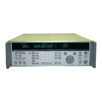
Fluke 6080AN Service Manual (296 pages)
SYNTHESIZED SIGNAL GENERATOR
Brand:
Fluke
| Category:
Portable Generator
| Size: 7.06 MB
Table of Contents
Table of Contents
3
Title Page
4
List of Tables
11
Introduction
15
Introduction and Specifications
15
Unpacking the Signal Generator
15
Safety
16
Accessories
17
Accessories Included with each Signal Generator
17
Signal Generator Specifications
17
General Description
33
Introduction
33
Theory of Operation
33
Amplitude Modulation
34
Frequency
34
Frequency Modulation
34
Front Panel Section
34
Functional Description
34
Internal Modulation Oscillator
34
Phase Modulation
34
Pulse Modulation
34
Rear Panel Section
34
Upper/Lower Module Sections
34
Frequency Coverage Bands
35
Digital Controller Software Description
38
Power Supply Description
38
User Interface
38
Calibration/Compensation Memory
39
Self-Test
39
Status Signals
39
Closed-Case Calibration
41
Introduction
41
Front Panel Calibration
42
Remote Calibration
42
Calibration Data
43
Am Calibration
44
Front Panel am Calibration Procedure
44
Front Panel Controls for am Calibration Procedure
45
Remote am Calibration Procedure
46
Fm Calibration
47
Remote Programming Commands for am Calibration Procedure
47
Front Panel Controls for FM Calibration Procedure
48
Front Panel FM Calibration Procedure
48
Remote FM Calibration
49
Remote Programming Commands for FM Calibration Procedure
50
Rf Level Calibration
50
Front Panel Level Calibration Procedure
51
Front Panel Controls for Level Calibration Procedure
52
Remote Level Calibration Procedure
53
Reference Oscillator Calibration
54
Remote Programming Commands for Level Calibration Procedure
54
Front Panel Controls for Reference Oscillator Calibration Procedure
55
Front Panel Reference Oscillator Calibration Procedure
55
Remote Reference Oscillator Calibration Procedure
56
Remote Programming Commands for Reference Oscillator Calibration Procedure
57
Introduction
59
Performance Tests
59
Test Equipment
59
Power-On Test
62
Frequency Accuracy Test
63
Synthesis Test
63
High-Level Accuracy Test
64
High-Level Accuracy Test Conditions
65
High-Level Accuracy Test Conditions Sample
66
MID-Level Accuracy Test
66
Low-Level Accuracy Test
67
Alternate-Level Accuracy Test
68
Flatness Test
71
Output Leakage Test
72
Harmonic and Line-Related Spurious Test
73
Phase Noise and Non-Harmonic Spurious Tests
74
Modulation Tests
75
Modulation Tests Requirements
75
AM Test Conditions
77
Voltage Standing-Wave Ratio (Vswr) Tests
81
Pulse Tests
82
Access Procedures
87
Introduction and Safety
87
Access Instructions
89
Location of Major Assemblies
89
Removing the Front Panel Section
89
Removing the Rear Panel Section
89
Removing the A2 Coarse Loop PCA
90
Removing the A3 Sub-Synthesizer VCO PCA
90
Removing the A4 Sub-Synthesizer PCA
91
Removing the A5 Coarse Loop VCO PCA
91
Removing the A6 Mod Oscillator PCA
91
Removing the A8 Output PCA
91
Removing the A10 Premodulator PCA
92
Removing the A11 Modulation Control PCA
92
Removing the A9 Sum Loop VCO PCA
92
Removing the A12 Sum Loop PCA
93
Removing the A13 Controller PCA
93
Removing the A14 FM PCA
94
Removing the A20 Attenuator/Rpp Assembly
94
Removing the A22 Delay Cable Assembly
94
Circuit Descriptions, Troubleshooting, and Alignment
97
Introduction
97
Module Exchange Assemblies
100
Module Replacement
100
A1 Display PCA
101
A2 Coarse Loop PCA
101
A3 Sub-Synthesizer PCA
101
A4 Sub-Synthesizer PCA
101
A5 Coarse Loop VCO PCA
101
A6 Mod Oscillator PCA
101
A7 Relay Driver PCA
101
A8Output PCA
101
A9 Sum Loop VCO PCA
101
A10 Premodulator PCA
102
A11 Modulation Control PCA
102
A12 Sum Loop PCA
102
A13 Controller PCA
102
A14 FM Board PCA
102
A15 Power Supply PCA
102
A19 Switch PCA
102
A20 Attenuator/Rpp Assembly (A7, A21, A30)
102
A22 Delay Line Assembly (A25+A26+Delay Cable+Trim Cable)
102
Updating Compensation Memory with Module Exchange Data
103
Digital Tests
104
Parts Replacement
104
Self-Test Description
104
AM Test Conditions
105
AM Tests
105
FM Tests
105
ØM Tests
105
DC FM Tests
106
DCFM Test
106
FM Tests
106
Phase Modulation Test Conditions
106
Coarse Loop Tests
107
Sub-Synthesizer Tests
107
Sum Loop Tests
107
Filter Tests
108
Pulse Modulator Tests
108
RF Output Tests
108
Filter Tests
109
Status Signals and Codes
109
Status Signals and Status Codes
109
Digital Control Latch Test
110
Instrument Diagnostic State
110
Set Internal Dacs
110
Software Diagnostic Functions
110
Display Synthesizer Loop Frequencies
111
1. Power Supply Block Diagram 6A-1
113
2. Power Supply Circuit Description 6A-1
113
Power Supply
113
3. Power Supply Troubleshooting 6A-4
116
4. Troubleshooting Procedure 6A-4
116
5. Power Supply Adjustment Procedure 6A-5
117
1. Digital Controller Block Diagram 6B-1
119
10. Status and Control 6B-4
119
2. Digital Controller Circuit Description (A13) 6B-1
119
3. Microprocessor 6B-1
119
4. Memory 6B-1
119
6. Front Panel Interface 6B-3
119
7. IEEE-488 Interface 6B-3
119
8. Attenuator Control Interface 6B-3
119
Digital Controller
119
11. Digital Controller Troubleshooting 6B-4
122
13. Microprocessor Kernel 6B-5
123
15. Power-On Reset 6B-5
123
16. Unused Microprocessor Inputs 6B-5
123
17. Bus Error 6B-5
123
19. Microprocessor Bus 6B-6
124
20. Address Decoder 6B-6
124
22. Calibration/Compensation Memory 6B-8
126
23. Calibration/Compensation Memory Status 6B-8
126
24. Repairing Calibration/Compensation Memory Checksum Errors
127
26. Front Panel Circuit Description 6B-9
127
Calibration/Compensation Memory Origin Status
127
27. Display PCA 6B-10
128
28. Data Communications 6B-10
128
29. Display Filament Voltage 6B-10
128
30. Bright-Digit Effect 6B-10
128
31. Switchboard Interface 6B-10
128
32. Remote Footswitch 6B-10
128
33. Edit Knob Interface 6B-11
129
34. Display Blanking 6B-11
129
35. Operate/Standby Selection 6B-11
129
36. Front Panel Troubleshooting 6B-11
129
37. Display and Controls 6B-11
129
1. Frequency Fault Tree 6C-1
131
2. Sub-Synthesizer Block Diagram 6C-1
131
3. Sub-Synthesizer Circuit Description (A4) 6C-1
131
Frequency Synthesis
131
4. Sub-Synthesizer Troubleshooting 6C-9
139
5. Sub-Synthesizer Adjustments 6C-13
143
6. Steering DAC Full Scale Adjustment 6C-13
143
7. Lower Clamp Adjustment, R99 6C-13
143
SSB Mixer lo Drive Adjustment, R106
144
Upper Clamp Adjustment, R98
144
10-Khz Notch Adjustment, L56
145
11. Sub-Synthesizer Vco (A3) Circuit Description 6C-16
146
12. Sub-Synthesizer Vco Troubleshooting 6C-16
146
13. Coarse Loop Circuit Description (A2) 6C-17
147
14. Reference Section Block Diagram 6C-17
147
15. Coarse Loop Block Diagram 6C-20
150
16. Coarse Loop Troubleshooting 6C-22
152
17. Coarse Loop Pca Adjustments 6C-26
156
Discriminator Video Amplifier Offset Adjustment, R102
156
40-Mhz Oscillator Adjustment, L601
158
Acquisition Oscillator Level Adjustment, R227
158
Steering Gain Adjustment, R221
158
80-Mhz Filter Tuning, L612 and L613
159
2-Mhz Notch Adjustment, L205
160
80-Mhz Level Adjustment, R617
160
25. Alternate Reference Frequency Selection 6C-31
161
26. Coarse Loop Vco (A5) Circuit Description 6C-31
161
27. Coarse Loop Vco Troubleshooting 6C-32
162
29. Sum Loop (A12) Circuit Description 6C-34
164
31. Audio Section 6C-35
165
33. Sum Loop Assembly Adjustments 6C-41
171
Steering Level Adjustment, R112
171
Buffer Gain Match Adjustment, R121
172
FM Null Adjustment, R116
172
Loop Gain Adjustment, R167
173
39. Sum Loop Vco (A9) Circuit Description 6C-44
174
Acquisition Oscillator Level Adjustment, R132
174
40. Sum Loop Vco Troubleshooting 6C-45
175
Rf Level/Am
177
5. Leveling Loop 6D-5
181
6. Level Control 6D-6
182
9. Output Assembly Test Point Signal Information 6D-9
185
Mod Control PCA Level DAC Offset Adjustment, R23
186
Mod Control PCA am DAC Offset Adjustment, R8
187
Mod Control PCA Detector Offset Adjustment, R28
188
14. Mod Control PCA am Depth Adjustment, R10 6D-13
189
15. Mod Control PCA RF Level Adjustment, R20 6D-14
190
17. Mod Control PCA Sum Steer Gain Adjustment 6D-15
191
Mod Control PCA External Modulation Level Indicator Adjustment, R71
191
Output PCA Het Mixer Level Adjustment, R72
192
19. Output PCA Het Level Adjustment, R10 6D-17
193
20. Premodulator PCA Bandwidth Adjustment, R51 and C7 6D-17
193
Output PCA Q16 Bias Adjustment, R96
194
22. Output PCA Q9 Bias Adjustment, R1 6D-19
195
23. Output PCA) Gain Flatness Adjustment, C201 6D-19
195
27. Attenuator/Reverse Power Protection (Rpp) 6D-20
196
28. Attenuator Rpp Troubleshooting 6D-21
197
Frequency and Phase Modulation
199
4. Oscillator Section 6E-2
200
5. Divider Section 6E-4
202
6. Phase Detectors, Loop Circuits, and Logic Section 6E-4
202
13. Frequency Check 6E-11
209
17. Adjustments on the Modulation Control PCA (A11) 6E-13
211
18. Alignment of FM PCA (A14) 6E-14
212
1. Modulation Oscillator Block Diagram 6F-1
217
Internal Modulation Oscillator
217
Internal Modulation Oscillator
218
4. Pulse Generator 6F-3
219
5. Signal Routing 6F-3
219
7. Direct Digital Synthesizer Troubleshooting 6F-4
220
Mod Oscillator Troubleshooting and Adjustments 6F-4
220
Section 7
223
List of Replaceable Parts
223
Table of Contents
223
How to Obtain Parts
224
Introduction
224
Service Centers
225
Advertisement
Advertisement
Related Products
Fluke 6080A
Fluke 6070A
Fluke 6071A
Fluke 6062A
Fluke 6060A
Fluke 6060AN
Fluke 6060B
Fluke 6050H
Fluke 6055
Fluke Comark Diligence 600
Fluke Categories
Measuring Instruments
Test Equipment
Multimeter
Thermometer
Laboratory Equipment
More Fluke Manuals
Login
Sign In
OR
Sign in with Facebook
Sign in with Google
Upload manual
Upload from disk
Upload from URL