Sign In
Upload
Manuals
Brands
FLENDER Manuals
Adapter
N-EUPEX
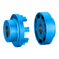
FLENDER N-EUPEX Pin Coupling Manuals
Manuals and User Guides for FLENDER N-EUPEX Pin Coupling. We have
2
FLENDER N-EUPEX Pin Coupling manuals available for free PDF download: Operating Instructions Manual, Manual
FLENDER N-EUPEX Operating Instructions Manual (70 pages)
A, B, ADS, BDS types
Brand:
FLENDER
| Category:
Adapter
| Size: 0.85 MB
Table of Contents
Safety Instructions
4
Table of Contents
5
1 Introduction
9
About These Instructions
9
Text Attributes
9
Copyright
9
Service and Support
9
Operating Instructions
10
2 Safety Instructions
11
General Information
11
Table 2-1 General Warnings
11
Intended Use
13
Safety Instructions for a Coupling for Use in Potentially Explosive Atmospheres
13
Marking
13
Spare Parts
13
Conditions of Use
15
General Warning Notices
16
Table 2-2 Temperature Classes (TX) for Explosive Atmospheres as a Result of Gases, Vapours or Mists
16
Table 2-3 Maximum Surface Temperature (TX) for an Explosive Atmosphere as a Result of Dust/Air Mixtures
16
3 Description
19
Figure 3-1 Type a and ADS
19
Figure 3-2 Type B and BDS
20
4 Application Planning
21
Transport of the Coupling
21
Storage of the Coupling
21
Figure 4-1 Transport Symbols
21
Table 4-1 Types of Preservative Agents for Long-Term Storage
22
5 Assembly
23
Preparatory Work
23
Milling the Parallel Keyway
24
Table 5-1 Recommended Assigned Fits for Bores with Parallel Key Connection
24
Milling the Parallel Keyway
25
Figure 5-1 Tolerances for Finished Bore
25
Machining an Axial Locking Mechanism
26
Figure 5-2 Diameter and Axial Position of the Tapped Hole in the Hub
26
Balancing the Coupling
28
Figure 5-3 Position of the Balancing Bore for Single-Plane Balancing
29
Figure 5-4 Position of the Balancing Bore for Two-Plane Balancing
29
Assembling the Coupling
30
Aligning the Coupling
31
Purpose of Alignment
31
Possible Misalignment
32
Axial Misalignment
32
Angular Misalignment
32
Figure 5-5 Possible Misalignment
32
Radial Misalignment
33
6 Commissioning
35
7 Operation
37
Normal Operation of the Coupling
37
Faults - Causes and Rectification
37
Procedure in the Event of Malfunctions
37
Identifying the Fault Cause
37
Possible Faults
38
Possible Causes
39
Correcting Faults
40
Replacing Wearing Parts
40
Correcting the Changed Alignment
41
8 Servicing
43
Maintenance Intervals
43
Maximum Permissible Torsional Backlash
44
Figure 8-1 Markings for Calculating the Torsional Backlash
44
Replacing Wearing Parts
45
Figure 8-2 Tapped Jacking Hole for Loosening Coupling Part 3 (3)
45
Removing the Coupling
46
9 Service and Support
49
Contact
49
10 Disposal
51
11 Spare Parts
53
Ordering Spare Parts
53
Spare Parts Drawing and Spare Parts List
54
Types a and ADS
54
Figure 11-1 Spare Parts Drawing for Types a and ADS
54
Types B and BDS
55
Figure 11-2 Spare Parts Drawing for Types B and BDS
55
Technical Data
57
Speeds, Geometry Data and Weights
57
Type a
57
Figure A-1 Type a
57
Type B
59
A.1.2 Type B
59
Type ADS
60
Figure A-3 Type ADS
60
A.1.3 Type ADS
60
Type BDS
61
Figure A-2 Type B
61
Figure A-4 Type BDS
61
A.1.4 Type BDS
61
Shaft Misalignment Values During Operation
62
Tightening Torques and Widths A/F
63
Tightening Procedure
64
Flexible Elements (12)
64
Use and Storage of Flexible Elements (12)
64
A.4 Tightening Procedure
64
N-EUPEX Flexible Elements (12)
65
A.5.2 N-EUPEX Flexible Elements (12)
65
N-EUPEX DS Flexible Elements (12)
66
A.5.3 N-EUPEX DS Flexible Elements (12)
66
Quality Documents
67
Declaration of Conformity
67
Advertisement
FLENDER N-EUPEX Manual (40 pages)
Flexible Couplings
Brand:
FLENDER
| Category:
Industrial Equipment
| Size: 0.99 MB
Advertisement
Related Products
FLENDER N-EUPEX DS
FLENDER N-EUPEX-DS
FLENDER N-EUPEX DK
FLENDER N-EUPEX DKS
FLENDER N-BIPEX BWN
FLENDER N-BIPEX BWT
FLENDER N-BIPEX BNT
FLENDER Categories
Industrial Equipment
Accessories
Sander
Adapter
Tools
More FLENDER Manuals
Login
Sign In
OR
Sign in with Facebook
Sign in with Google
Upload manual
Upload from disk
Upload from URL